11.2.2. Burn binary to flash for DA1458x, DA1453x and DA14585-586
From Programmer menu select the Flash Code tool
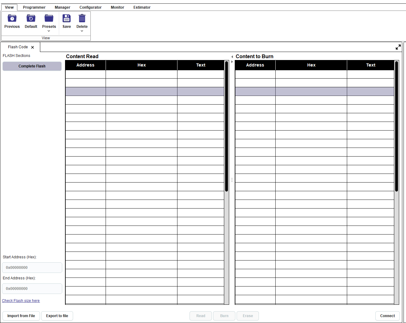
Figure 199 Flash Code initial screen
From Board menu select a UART or JTAG interface. If UART interface is selected also select the correct pins from Board Setup tool. User should also verify that the correct flash pins have been selected.

Figure 200 Interface selection
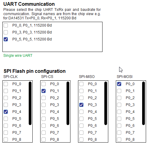
Figure 201 Default pin selection from Board Setup tool for DA14531
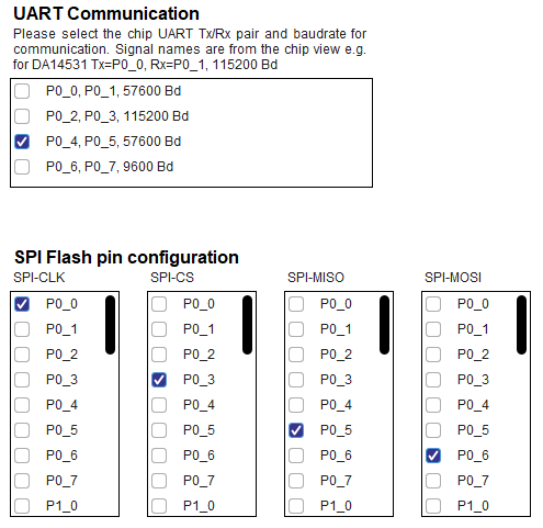
Figure 202 Default pin selection from Board Setup tool for DA14585

Figure 203 Default pin selection from Board Setup tool for DA14583-01
Press the Connect button on the bottom of the tool.

Figure 204 Flash Code connect button
The connect process will download the appropriate firmware in chip RAM to support the burn process. If the UART interface is selected the RESET button on the board may need to be pressed. Please check the log window for any requesting the user’s interaction.
Press the Read button to read the contents of the flash. The contents are presented on the left table named “Content Read*. Verify that the flash is empty.

Figure 205 Empty Flash
Press the Import from File button and the import wizard appears
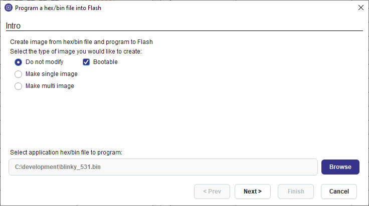
Figure 206 Import wizard step 1
Select the application file to burn in bin or .hex format. If option do not modify is selected, the file should contain an image. Image may become bootable by clicking the respective checkbox. Please refer to Flash Code for single and multi image options. Press Next
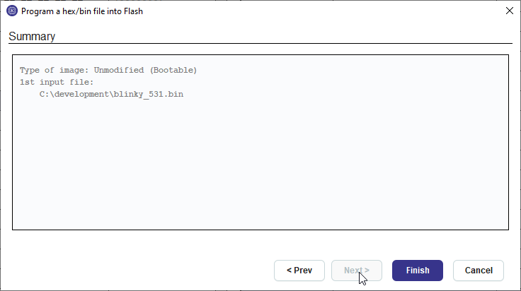
Figure 207 Import wizard step 2
Press Finish and the Content to Burn table is populated with the data to burn.

Figure 208 Content to burn table
Check that the start address to burn the application is 0x00 (Figure 208) and press the Burn button.
After successful burn the “Content Read” table is updated, the RESET command is sent to the chip and the application starts running.

Figure 209 Memory contents after flash burn
For full documentation of the Flash Code tool refer to Flash Code