11.1. User interface
11.1.1. The ribbon menu
From version 4.7 SmartSnippets™ Toolbox introduces ribbon menu to access its tools and functions. Tools are grouped under 5 categories for easy access: Programmer, Manager, Configurator, Monitor and Estimator. The tools under each group and the set of available groups depend on the selected device: different toolset is available per device family. SmartSnippets™ Toolbox even allows for creating custom layouts with the tools of interest for faster and accurate access.
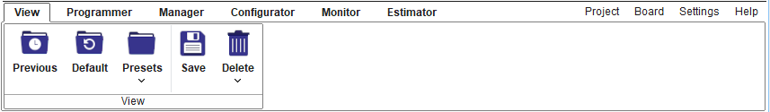
Figure 177 SmartSnippets™ Toolbox ribbon menu
The following sections introduces the tools available under each ribbon group. Only a brief description of each tool is presented in the following section. Please refer to the left side menu for full tool presentation. Note that some of the groups are not available for all families. For example Configurator group is not available for DA1468x, DA1469x, DA1470x and DA1459x families and Estimator group is not available for DA1468x and DA1469x families. Each tool under a group is accessible through a dedicated button. By clicking on a button, the corresponding window becomes visible and takes focus. Moving the mouse over the button will provide a small description of each SmartSnippets™ Toolbox tool.
11.1.2. Group View
This group contains buttons that help user to organize the application view layout. User can load the default or last saved view layout for this family, create new or delete a previously created view layout.

Figure 178 View ribbon group
| Icon | Description |
|---|---|
 |
Previous user specified view layout is the latest layout that has been saved for each board family. Latest view layout is saved when user changes family or when user exits Toolbox |
 |
Load default view layout which includes Power Profiler tool and some Estimator group tools available only for certain families. |
 |
Save new custom view layout will save the locations and sizes of all currently opened tools |
 |
Load custom view layout |
 |
Delete custom view layout |
11.1.3. Group Programmer
Programmer group contains all the tools needed to program any memory resource available on the DK as well as the SOC such as OTP, external or embedded FLASH for code, external FLASH or EEPROM for data etc.

Figure 179 Programmer ribbon group for DA1453x family

Figure 180 Programmer ribbon group for DA1469x family
This group contains the following tools:
| Icon | Description |
|---|---|
 OTP |
Program OTP Memory (Reloaded version of OTP Programmer tools) |
 EEPROM Programmer |
Download image file to EEPROM |
 Proprietary Header Programmer |
Burn header or NVDS to EEPROM or SPI flash memory |
 QSPI Partition Table |
Manage QSPI Flash partitions |
 Flash Code |
Program the part of the Flash that contains executable code |
| Flash Data |
Program the Flash |
 RAM |
Program the System RAM |
 OTA Services |
Software patching and firmware download over the air |
| SUOTA |
Software update over the air |
11.1.4. Group Manager
Manager groups contains all the tools used for setting the SOC into predefined states for monitoring or testing real-time.

Figure 181 Manager ribbon group for DA1453x family

Figure 182 Manager ribbon group for DA1469x family
This group contains the following tools:
| Icon | Description |
|---|---|
 RF Master |
RF Master tests |
| XTAL Manager |
XTAL configuration |
| IO Manager |
GPIO configuration |
| Registers Access |
Registers’ configuration |
 Terminal |
UART Terminal, available only when connection is over UART |
 Terminal Scripting |
11.1.5. Group Configurator
The Configurator Group tools help in defining certain states of the SoC during the actual application. The output of these group’s tools shall be structures that are natively supported by the SDK.

Figure 183 Configurator ribbon group for DA1453x family
This group contains the following tools:
| Icon | Description |
|---|---|
 Board Setup |
Manage communication with the chip |
11.1.6. Group Monitor
This group of tools contains important monitoring applications that are of interest to a developer on Renesas’s DK and SDK. While some of these applications are passively printing values coming from a hardware-based measuring circuitry (Power Profiler), others need certain, code images to be downloaded so that they can display the required data.

Figure 184 Monitor ribbon group for DA1458x family
This group contains the following tools:
| Icon | Description |
|---|---|
 Log |
Log messages from all tools |
 Power Profiler |
Plot the current drawn by the chip’s battery |
 Data Rate Monitor |
Monitors the overall receive and transmit rate over Bluetooth |
11.1.7. Group Estimator
Estimator group contains tools that allow the user to estimate various chip specific metrics by testing various usage scenarios.

Figure 185 Estimator ribbon group for DA1458x family

Figure 186 Estimator ribbon group for DA1470x family
This group contains the following tools:
| Icon | Description |
|---|---|
 Battery Lifetime Estimator |
Estimate battery lifetime for the selected device family |
 Sleep Mode Advisor |
Analyze power consumption for target application |
 Graphics FPS Estimator |
Estimate the typically and maximum achievable frame rate |
11.1.8. Tool specific groups
Apart from the groups mentioned above SmartSnippets™ Toolbox provides two ribbon groups / toolbars containing tool specific utilities that are activated when certain tools are selected:
- Power Profiler: is activated when the respective tool is selected and is hidden once the respective tool is closed. The functionality of this toolbar is described under Power Profiler section.
- RF Master: is activated when RF Master, XTAL Manger, Register Access or IO Manager tools are selected and hidden if none of these tools are open. The functionality of this toolbar is described under RF Master section.
11.1.11. Board Menu
This menu can be used to configure the connected device(s) and manage the Support Pack.
- Device: (Figure 187) User can select from the list the device name that matches the connected device. In case the connected device is detected, the device is automatically selected.
- UART: (Figure 188) User can select from the list the UART port of the connected device. In case the connected device is detected, the UART port is automatically selected. Unchecking the UART checkbox indicates that the user doesn’t want UART interface to be used for communication with the device. If an alternative interface has been configured (e.g. JTAG) certain tools that can use either of the two interfaces will still be functional and use the alternative interface instead. Tools that require UART interface to communicate with the device will have buttons that depend on communication over UART disabled until the UART interface is configured.
- Power Profiler: User can select from the list the Power Profiler port of the connected device. In case the connected device is detected, the Power Profiler port is automatically selected. Unchecking the Power Profiler checkbox indicates that the user doesn’t want to communicate with the device over the Power Profiler port. This means that if no Power Profiler port is selected or the Power Profiler checkbox is unchecked, the user will not be able to use the Power Profiler tool.
- JTAG: (Figure 189) User can select from the list the JTAG serial of the connected device. In case the connected device is detected, the JTAG serial is automatically selected. Unchecking the UART checkbox indicates that the user doesn’t want JTAG interface to be used for communication with the device. If UART interface has been configured this will be used instead in that case. If both JTAG and UART interfaces have been configured, JTAG interface will be used which is faster than UART.
- Close Debug Session: Applies to JTAG interface. Terminates the communication with the debugger.
- Cannot See my Board: Help message that informs the user on what can be done in order for the application to identify the connected device(s).
- Support Pack Info: (Figure 190) Provides information about the used Support Pack: Its type (bundled or custom or online resource), its location, the devices it supports e.t.c..
- Check Online for Updates: Checks for Support Packs updates for the selected device.
- Device Info: (Figure 191) Provides info of the connected device once it has been detected. Info includes the device core ID, its family and name and its interfaces. Refresh button on Device Info dialog triggers again the detection logic. JTAG Info button reads device info over JTAG interface.
- Detect Device: (Figure 192) Detects connected device(s). Note that the user may have to press the hardware reset button in order for the device detection firmware to be downloaded over UART to the device. A message prompting the user to press the HW reset button will be added to the Log in that case. In case a single device is detected, when the user presses OK on the device detection dialog, the device type, UART, JTAG and SPI interfaces will be automatically selected under the Board menu. If more than one devices are detected, the user will be asked to select with which device the application should work with. Once the user selects one of the detected devices the entries under the Board menu regarding device name, UART, JTAG and SPI interface will be automatically selected.

Figure 187 Devices Menu |
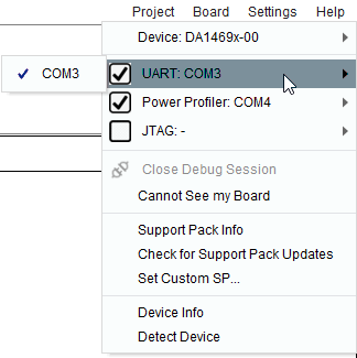
Figure 188 UART Menu |
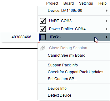
Figure 189 JTAG Menu |
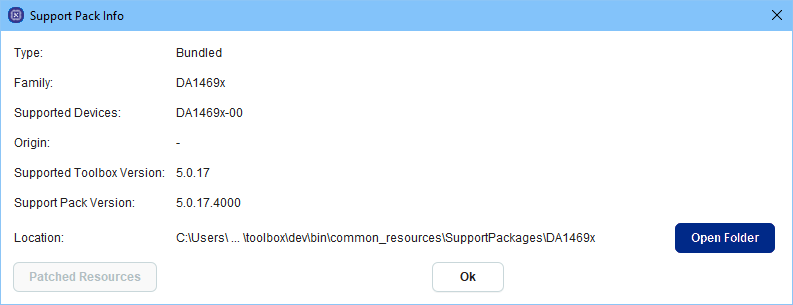
Figure 190 SP Info Menu |
||

Figure 191 Device Info |
||
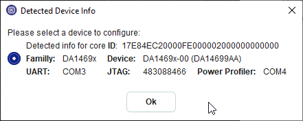
Figure 192 Device Detection Results |
||
11.1.12. Settings Menu
This menu can be used to configure device and application parameters.
- Advanced Settings: (Figure 193) Advanced users can select from a list the visible tools and memory sections in tools. Non advanced users will be able to see only the default set of the tools. Note that some tools are only available for certain device families. These tools cannot be activated from the advanced settings menu if the selected device is not a member of the family for which the tool is available.
- Device Settings: (Figure 194) User can specify the size of the Flash attached to the device that is being currently used. The menu popup dialog initially indicates the default Flash size for the selected device. The user can change this value in case a non default flash is being used. Flash size value is saved and will be used again for the same device family in subsequent SmartSnippets™ Toolbox sessions.

Figure 193 Advanced Settings Menu |
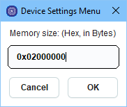
Figure 194 Device Settings Menu |