4. The Hardware overview
The SmartBond TINY™ Module is based on the Renesas DA14535 SoC configured in buck mode. With an integrated 1 Mbit flash, 32 MHz XTAL and a printed antenna, the module enables a faster time to market at reduced development costs.
- The module, as seen also in Figure , is comprised of:
1 Mbit SPI FLASH
32 MHz XTAL
2 decoupling capacitors
A power inductor
A CLC filter and matching components for the printed antenna
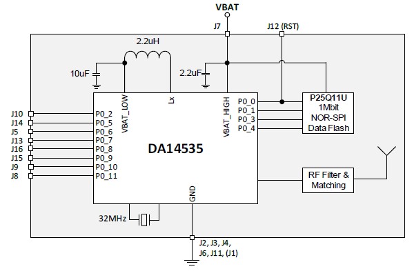
Figure 4 DA14535 SmartBond TINY™ Module Block Diagram
4.4. Pin Definition
The figure below shows the pin assignment of the DA14535 TINY™ Module pinout.
The DA14535 TINY™ Module Datasheet in the DA14535 TINY™ Module Datasheet includes an overview of the pins description.

Figure 9 The DA14535 module Pinout Diagramm
4.5. The Module daughterboard
Figure 10 and Figure 11 present the DA14535 TINY™ Module Daughterboard.

Figure 10 The DA14535 module Daughterboard

Figure 11 The DA14535 module Daughterboard bottom
4.6. Connecting to the Mother Board
Figure 12 shows how the DA14535 TINY™ Module is connected to the DA14535 mother board.

Figure 12 The DA14535 module connected to the DA14535 mother Board
Note
The UM-B-169 DA14535 Devkit Pro Hardware User Manual shows How to Configure Power of DA14535 mother board.
The UM-B-165 DA14535 Getting Started with the Pro Development Kit shows how to setup the hardware development environment, install required software, download, and run an example application on the DA14535.