4. First Setup
This first setup guide will provide instructions to set up the most basic development environment with a single PLT, a single RFTU, and a single DUT. For more advanced setup with multiple of each component, please consult the Connectivity PLT User Manual.
4.1. Connecting the Hardware
The first thing to connect to the Connectivity Production Line Tool is the power supply unit. The power connector (Figure 2) is delivered with all Connectivity Production Line Tool packages. But the power supply and cables are not. So, the power cable has to be created first according to the pinout marked in Figure 2.

Figure 2 Power connector
Either one of the positive and negative terminals can be used to supply the power. The power supply connected to those terminals should be set to deliver 12V 1A in constant voltage mode.

Figure 3 Power wiring
Caution
Use wires and connectors specified for the voltage and current. In case of 12V 1A, most 24AWG insulated flexible wires suffice. Always follow the manufacturer’s recommendations.
The next connection is the data wiring from the PLT to the host PC. This is done using the USB A to B cable that is included with the package. Use the correct USB port on the PLT like illustrated in Figure 4.

Figure 4 Data wiring
The RFTU can be connected to the host PC in many ways, all described in the user manual. But for this tutorial, the RFTU will be simply connected to the available USB type A port like shown in Figure 5.

Figure 5 RFTU connection
The final hardware connection to make is the power and data connection to the DUT. The DUT chosen for this getting started is the DA14531 USB Kit, so please refer to Section 6.2 for detailed instructions how to connect the DA14531 USB Kit.

Figure 6 DA14531 USB kit connection
4.2. Installing the Software
The Connectivity Production Line Tool software package can be downloaded via this download link: Software Package. After downloading and extracting the package, the installer can be found in ./Installer/installer.msi. The installer will guide you through the process of installation. For this tutorial we will assume all the default installation options. For more advanced installations, please refer to the Installation section of the Connectivity PLT User Manual.
4.3. Configuring the Software
After connecting the hardware and installing the software, there is some configuration required to let the software know what hardware is connected. This configuration is done using the Connectivity PLT Configuration Application which can be launched from the start menu.
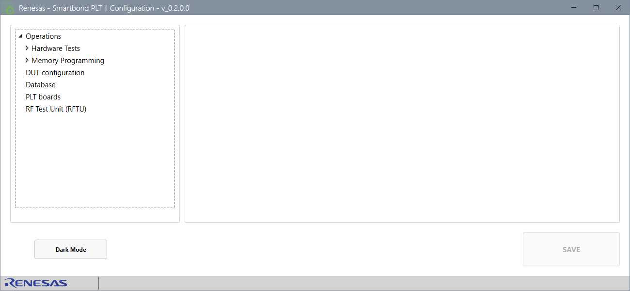
Figure 7 Connectivity PLT Configuration Application
Tip
When any settings are changed in the Connectivity PLT Configuration Application, the changes must be saved using the save button in the bottom right corner.
The first thing to check is the configured PLT hardware in the PLT Boards section. First thing to check here is the Activity checkmark should be set only for Board 1.

Figure 8 Connectivity PLT Configuration Application Board Activity
Next, the active test sites should be configured for the connected PLT board. In this getting started we will only be testing a single DUT, so only one (the first) test site should be active. This can be done by unselecting the Activity box for all test sites except the first one on the active PLT board.

Figure 9 Connectivity PLT Configuration Application Test Site Activity
To set up the RFTU for testing, the correct COM port must be configured.

Figure 10 Connectivity PLT Configuration Application RFTU COM port
Tip
The Windows Device Manager can be used to find out which COM port the RFTU is connected to. Look for a device called JLink CDC UART Port (COMx).
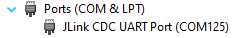
Figure 11 RFTU COM port
Warning
The RFTU COM port will only show up if the PLT board is powered up. If this is not the case, the RFTU can be plugged directly into the USB port of the PC as a debugging step.
This concludes all the steps needed to setup the PLT for testing. Running tests will be explained in Section 5.