11. Sleep Mode
Before we start working with sleep mode, we will take a look at the power consumption of our implementation. The Power Profiler tool of the SmartSnippets™ Toolbox will allow us to observe how power is consumed in real time.
Power Profiler
The Power Profiler is available on the PRO development kits, and you can see how to use it here. The DA1453x USB kit and the DA14585/6 BASIC kits do not support the Toolbox Power Profiler.
- Running our firmware at its current state should expose an advertisement event looking something like this :

Figure 16 Power consumption of our current implementation (DA14531 in buck mode).You can stop the Power Profiler and use the scroll wheel of your mouse to zoom in on a single event
What we observe here is an idle current of approximately 0.25mA. We can also see an advertisement on three channels, each consisting of one TX pulse (approximately 3.5mA) and one RX pulse (approximately 2.2mA).
Why enabling Sleep mode?
Between advertising events, the device really isn’t doing anything other than burning power, so we should enable sleep mode and thereby save a lot of power.
11.1. Enabling Sleep Mode
As mentioned in the introduction, sleep mode functionality is fully managed by the SDK.
All we have to do to enable this functionality is to change the default sleep mode in user_config.h from:
/******************************************
* Default sleep mode. Possible values are:
*
* - ARCH_SLEEP_OFF
* - ARCH_EXT_SLEEP_ON
* - ARCH_EXT_SLEEP_OTP_COPY_ON
*
******************************************
*/

- static const sleep_state_t app_default_sleep_mode = ARCH_SLEEP_OFF;
+ static const sleep_state_t app_default_sleep_mode = ARCH_EXT_SLEEP_ON;
- If we build the project and run it again (F7 then twice Ctrl+F5), we will see the following in the Power Profiler:

Figure 17 Our implementation with sleep enabled (DA14531 in buck mode)
Warning
The Chip wont go to sleep mode with the debugger attached.
The current has been reduced dramatically between the advertising events. In fact, the current has dropped from the 0.25mA we observed previously to as little as 1.2uA. We can also see that the device knows when to wake up for the next advertising event, and this is all completely handled by the SDK6. All we did was enabling sleep.
Using the DA14531 or DA1453x DevkitP, you may have noticed that you have to physically reset target to attach the debugger after you enabled sleep. You can get around this by lowering the J-Link clock speed to 2MHz. Open the Debug tab in Options for Target (Alt + F7) and change the Max Clock setting
- as shown below:
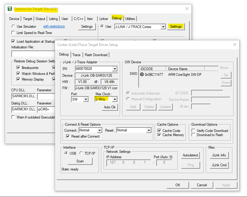
Figure 18 Change the J-Link clock setting when using the DA14531 PRO kit
Hint
You can find a lot more information about sleep mode in the DA1453x Sleep Mode Tutorial.
11.2. Waking up From Sleep
When the device wakes back up from sleep, it attempts to re-initialize the GPIOs and other peripherals.
This is achieved by calling the periph_init() function in user_periph_setup.c right after waking up.
For digital output pins, this presents an issue because the re-configuration of the output pin also sets the output state.
If you establish a BLE connection with our device, you might notice an issue. The LED, initially programmed to stay on for 2 seconds, now only briefly flashes after enabling sleep.
- By using the Power Profiler, you can observe the expected behavior:

Figure 19 The LED turns off when the device wakes up from sleep (DA14531 in buck mode)
The LED turns on when the connection is established but turns off as soon as we wake up for the next connection event.
- In the following we will fix this issue, by retaining the desired state of the LED in a variable and configure the digital output depending on the state of this variable.
First we will declare a boolean in such a way that it will be retained during sleep. In user_peripheral_template.c, right after the include statements at the top, declare a retained global boolean as shown below:
bool my_led_state __SECTION_ZERO("retention_mem_area0"); // @RETENTION MEMORY
We will then re-route the
app_on_initcallback to user space. This will provide us a place where we can initialize themy_led_stateboolean. In user_callback_config.h locate the code snippet below:static const struct arch_main_loop_callbacks user_app_main_loop_callbacks = { - .app_on_init = default_app_on_init, + .app_on_init = user_app_on_init, ~Now, add a prototype to this function in user_peripheral_template.h:
void user_app_on_init(void);
This gives us a function that we can use for initialization of our global variable. In user_peripheral_template.c add the following code:
void user_app_on_init(void)
{
   my_led_state = false;
   default_app_on_init();
}
We have implemented control of the LED in user_empty_peripheral_template.c.We must now make sure that our global boolean,
my_led_state, is set accordingly.In the
control_LED()function, as a last statement, add the following:my_led_state = state;
At this point we can rely on
my_led_stateto retain the desired LED state during sleep.
In
set_pad_functions()of user_periph_setup.c, replace the GPIO configuration of our LED pin with the following:extern bool my_led_state; GPIO_ConfigurePin(LED_PORT, LED_PIN, OUTPUT, PID_GPIO, my_led_state);
Build the project and run it again to ensure that the LED remains on for 2 seconds after a BLE connection is established.