11. Watch Demo Application
In this section the advantages of the LCD Controller and the GPU are combined, along with the flexibility provided by the LVGL graphics library, resulting in a watch face user interface example. The application code can be found at the Github Examples Repository, under the features/watch_demo_lvgl folder.
11.1. Building the Demonstration Example
The watch demo application contains four slightly different build configurations. Two Release build configurations and the respective debug configurations. These two build configurations differ at the optimization level of the C Compiler.
The DA1470x-00-Release_OQSPI_demo build configuration, with optimized size when building the project, supports touch operations with which the user can interact with the watch demo application by touching the LCD screen and browsing to the watch face screen, the menu and the different screens.
The DA1470x-00-Release_OQSPI_touch_simulation build configuration, with optimized size when building the project, which is used to get performance metrics for the FPS, the GPU rendering time and the CPU utilization. The touch is disabled, and a simulation of touch events is used to be able to switch between the current screens and measure the demo performance. The simulation is performed by the ui_simulation_thread task, which periodically notifies the GDI that there are touch data to be read.
The DA1470x-00-Debug_OQSPI_demo build configuration, with optimization for debug when building the project, supports touch operations with which the user can interact with the watch demo application by touching the LCD screen and browsing to the watch face screen, the menu and the different screens.
The DA1470x-00-Debug_OQSPI_touch_simulation build configuration, with optimization for debug when building the project, which is used to get performance metrics for the FPS, the GPU rendering time and the CPU utilization. The touch is disabled, and a simulation of touch events is used to be able to switch between the current screens and measure the demo performance. The simulation is performed by the ui_simulation_thread task, which periodically notifies the GDI that there are touch data to be read.
11.2. Running the Demonstration Example
This section describes the necessary steps to prepare the DevKit and other tools to successfully run the demonstration example. In this sample code, a QSPI touch shield is demonstrated. An E120A390QSR 1.19’’ AMOLED Oncell display model is required to test and check if the target application behaves correctly.
11.2.1. Using Resources
The resources are typically the images used in our graphics demonstration example. An image can be a file or a variable which stores the bitmap itself and some metadata. In our case, the resources are binary files written either in QUAD SPI Flash, in a predefined address which is stored in the image header of every single resource.
The PNG files at the watch_demo_lvgl/ui/demo/resources/bitmaps folder can be converted to raw binary files using the LVGL Online Image Converter
Choose the png image to be converted (e.g. activity.png).
Give a name to the output file (e.g. “activity”).
Specify the desired color format, one of the following.
True color: Simply stores the RGB colors (in whatever color depth LVGL is configured for).
True color with alpha: Like True color but it also adds an alpha (transparency) byte for every pixel.
True color chroma keyed: Like True color but if a pixel has the transparency it is expressed by using the LV_COLOR_CHROMA_KEY color set in lv_conf.h.
Specify the desired output format to be a Binary file with the desired color format.
Click the Convert button to download the resulting activity.bin file.
Though we have already build a single binary file containing all the required recources, it is still possible to rebuild the file with customized content. The prebuild binary file, named WatchDemoColoredResources.bin, can be found in the watch_demo_lvgl/ui/demo/resources/bitmaps folder.
To rebuild the binary file use the following procedure:
Convert the *.png files in the watch_demo_lvgl/ui/demo/resources/bitmaps folder to raw binary files using the LVGL Online Image Converter with the following settings:
Nr |
File |
Color format |
Output format |
|---|---|---|---|
1 |
clock_bg |
CF_TRUE_COLOR |
Binary RGB565 |
2 |
stamens |
CF_TRUE_COLOR_ALPHA |
Binary RGB888 |
3 |
tick_hour |
CF_TRUE_COLOR_ALPHA |
Binary RGB888 |
4 |
tick_minute |
CF_TRUE_COLOR_ALPHA |
Binary RGB888 |
5 |
tick_second |
CF_TRUE_COLOR_ALPHA |
Binary RGB888 |
6 |
timer |
CF_TRUE_COLOR_ALPHA |
Binary RGB888 |
7 |
reset_timer |
CF_TRUE_COLOR_ALPHA |
Binary RGB888 |
8 |
activity |
CF_TRUE_COLOR_ALPHA |
Binary RGB888 |
9 |
track |
CF_TRUE_COLOR |
Binary RGB565 |
10 |
compass_menu_icon |
CF_TRUE_COLOR_ALPHA |
Binary RGB888 |
11 |
compass |
CF_TRUE_COLOR |
Binary RGB565 |
12 |
compass_earth |
CF_TRUE_COLOR_ALPHA |
Binary RGB888 |
13 |
compass_index |
CF_TRUE_COLOR_ALPHA |
Binary RGB888 |
14 |
heart_rate |
CF_TRUE_COLOR_ALPHA |
Binary RGB888 |
15 |
messages |
CF_TRUE_COLOR_ALPHA |
Binary RGB888 |
16 |
sleep_monitor |
CF_TRUE_COLOR_ALPHA |
Binary RGB888 |
17 |
weather |
CF_TRUE_COLOR_ALPHA |
Binary RGB888 |
Convertor Table
Combine the binary files in the same sequence as in the above table. The offset of the individual files needs to exactly match the offset settings in the source file resources.c
#define CLOCK_BG_BITMAP_OFFSET          (0x0)
#define STAMENS_BITMAP_OFFSET           (0x4A44C)
#define HOUR_BITMAP_OFFSET              (0x58CDC)
#define MINUTE_BITMAP_OFFSET            (0x5A8A0)
#define SECOND_BITMAP_OFFSET            (0x5BC04)
#define TIMER_BITMAP_OFFSET             (0x5C4F8)
#define RESET_TIMER_BITMAP_OFFSET       (0x5EC0C)
#define ACTIVITY_BITMAP_OFFSET          (0x61320)
#define TRACK_BITMAP_OFFSET             (0x63A34)
#define COMPASS_MENU_BITMAP_OFFSET      (0x8AA34)
#define COMPASS_BITMAP_OFFSET           (0x8D148)
#define COMPASS_EARTH_BITMAP_OFFSET     (0xD7594)
#define COMPASS_INDEX_BITMAP_OFFSET     (0xF83B8)
#define HEART_RATE_BITMAP_OFFSET        (0xFBC10)
#define MESSAGES_BITMAP_OFFSET          (0xFE324)
#define SLEEP_MONITOR_BITMAP_OFFSET     (0x100A38)
#define WEATHER_BITMAP_OFFSET           (0x10314C)
Using Linux OS the following command can be used: cat <filename1>.bin <filename2>.bin <filename3>.bin > <final_file>.bin
Using Windows OS the following command can be used: copy <filename1>.bin + <filename2>.bin + <filename3>.bin + ….. <final_file>.bin
11.2.1.1. Burning Resources in FLASH
Copy the WatchDemoColoredResources.bin at the binaries folder of the SDK.
Open a Windows Powershell terminal.
Make use of the cli_programmer.exe application, stored in the binaries folder of the root SDK folder, to write the resources at the QUAD SPI Flash.
./cli_programmer.exe -s 115200 -i 115200 COM8 write_qspi 0x0 ./WatchDemoColoredResources.bin
Note
More information regarding the cli_programmer can be found in the Doxygen documentation of the SDK.
Note
Apart from the cli_programmer.exe application, the SmartSnippets Toolbox Tool can be used to write the resources to the FLASH, see the SmartSnippets Toolbox User Manual (UM-B-083).
11.2.2. Preparing and Connecting the LCD
The E120A390QSR 1.19’’ AMOLED Oncell display should be mounted on the 500-31-x interface board. Use the J37 LCD and CTP Connector to connect the 500-31-x interface board to the DA1470x Dev Kit (500-05-B).
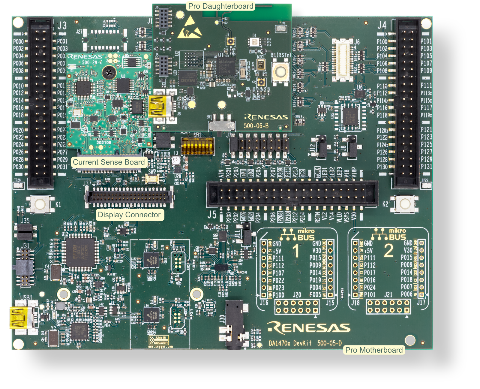
Figure 15 DA1470x Development Kit-Pro
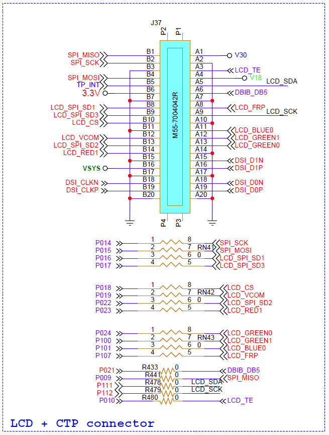
Figure 16 DA1470x Devkit-Pro Display and Touch Panel Connector

Figure 17 DA1470x Development Kit-Pro including AMOLED Display
11.2.3. Connecting External QSPI FLASH
On the DA1470x Motherboard, a 128-Mbit QUAD SPI flash can be added and take advantage of its high storage size. TThe external QUAD SPI storage flash is already soldered to the U15 connector.
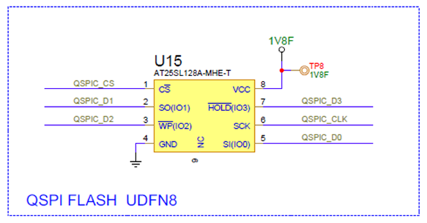
Figure 18 DA1470x Development Kit-Pro - QUAD SPI Flash
11.2.4. Running the Source Code
Use the USB1 port of the motherboard to connect the target device to your PC. This port is used to supply power to and communicate with the DA1470x SoC.
Import the demo example into the working directory.
Note
Make sure that the python_scripts folder is imported.
Download the already built firmware file to the OQSPI XIP Flash, using the scripts provided by the imported python_scripts. The user may select either program_oqspi_jtag script, using the J-Link with the lowest serial number, or program_oqspi_serial script, using the COM port with the lowest number.
Press the B1(RSTn) button on the DA1470x daughterboard to start the firmware execution.
11.2.4.1. Printing LOG Messages
During the demonstration example execution, either in the DA1470x-00-Debug_OQSPI_demo or in the DA1470x-00-Debug_OQSPI_touch_simulation build configuration, no log messages are printed since they adversely affect the whole GDI performance. In the DA1470x-00-Debug_OQSPI_touch_simulation build configuration the performance metrics are printed after the demo simulation has ended. When connecting a DA1470x DevKit to a host PC, two consecutive serial ports become available. The COM port with the lowest value is the one that the log messages are propagated. E.g. if COM8 and COM9 become available, COM8 will be used.
Open a serial terminal emulator.
Configure and create a new serial connection, to the COM port with the lowest value, using the parameters shown in Table 13.
Port Parameters |
Port Values |
|---|---|
Port number |
COM8 |
Baud rate |
115200 |
Parity |
None |
Data |
8 |
Stop Bit |
1 |
Flow control |
None |
Transmit delay per character (in msec) |
0 |
Transmit delay per line (in msec) |
0 |
11.3. Application Description
This application is a demonstration example for wearable devices with a watch user interface. The application takes advantage of the benefits supported by the MCU, the GPU and the graphics library. The 2 HW Layers that the DA1470x supports, can speed up the horizontal sliding when screen transitions occur. The GPU can accelerate most of the rendering processes, decreasing the rendering time, increasing the performance and releasing (offloading) the CPU to perform other operations.
11.3.1. Overview
The watch demo application contains five different screens, split between the watch face and the menu list of a wearable device. The first screen that the user can explore is a watch face screen, with 3 clock hands, hour hand, minute hand and the seconds hand, advancing every 100 milliseconds (Figure 19).
Figure 19 Watch Face
Sliding to the left from the watch face screen, the menu face screen appears, and the user can navigate to the applications list by vertically scrolling (Figure 20). The menu face screen contains applications such as timer, activity tracker, compass, heart rate tracker, messages, sleep monitor and weather information. The user can explore some of those applications by touching either each icon or anywhere in each application line. With a slide gesture to the right, the user can exit the applications screen and return to the menu screen. Only the timer, the activity tracker and the compass applications are implemented for this demo.
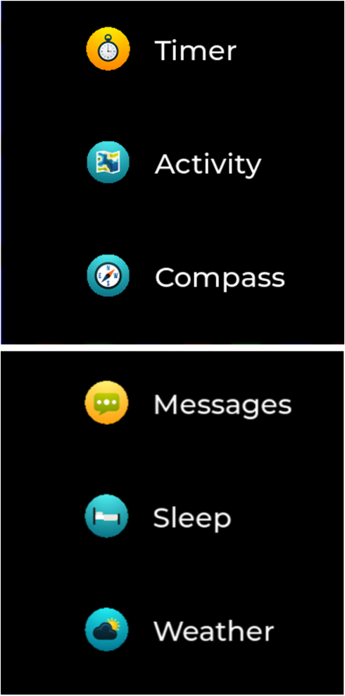
Figure 20 Application List Interface
Once the timer icon ![]() is clicked, the timer screen is rendered
(Figure 21) and the user can start or stop the timer by clicking the
timer icon
is clicked, the timer screen is rendered
(Figure 21) and the user can start or stop the timer by clicking the
timer icon ![]() and reset it from the reset icon
and reset it from the reset icon ![]() .
.
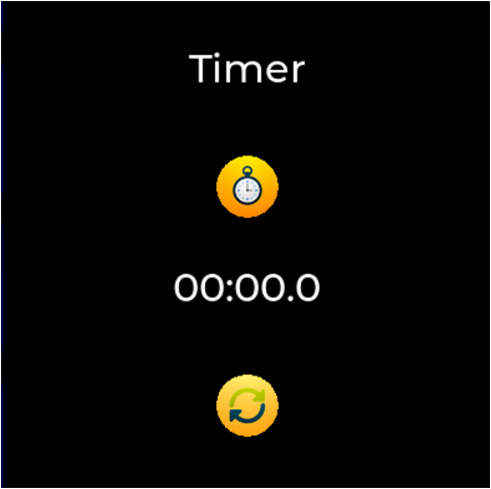
Figure 21 Timer Screen
Once the activity tracker icon ![]() is clicked, the activity screen
is rendered (Figure 22) and the user can monitor all tracked
fitness-related metrics such as distance walked or run, duration, pace,
cadence, calorie consumption, and heartbeat.
is clicked, the activity screen
is rendered (Figure 22) and the user can monitor all tracked
fitness-related metrics such as distance walked or run, duration, pace,
cadence, calorie consumption, and heartbeat.
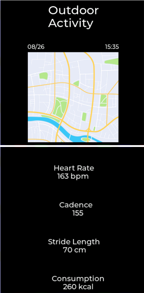
Figure 22 Activity Screen
Once the compass icon ![]() is clicked, the compass screen is
rendered (Figure 23). The compass data are simulated by a background
task and there is no magnetometer attached to the DA1470x DevKit to
provide real data.
is clicked, the compass screen is
rendered (Figure 23). The compass data are simulated by a background
task and there is no magnetometer attached to the DA1470x DevKit to
provide real data.
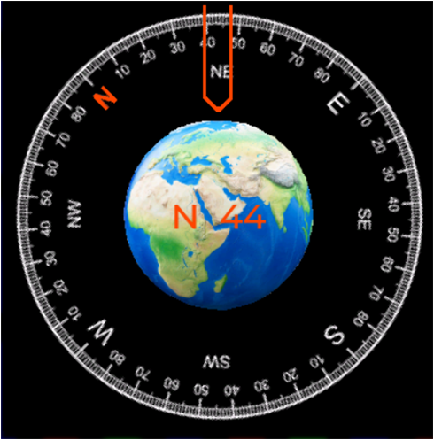
Figure 23 Compass Screen
11.3.2. Architecture/Implementation Details
The application consists of one parent object, created from the active screen of the default display, which is the container of 2 child objects, as shown at Figure 24. The first child object is assigned to the watch face and the second child object is assigned to the menu. The size of the parent object is twice the size of the display resolution (2 * DEMO_RESX * DEMO_RESY) and its relative position is set to the left and top side of the screen without any padding (either left or top). Each one of the children objects has DEMO_RESX * DEMO_RESY size and their position is relevant with the selected layout. The watch face screen is positioned at the left and top side of the screen without any padding (either left or top) and on the left of the menu screen, which is positioned at DEMO_RESX and top side of the screen.
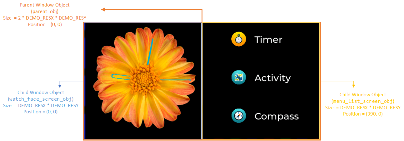
Figure 24 Application Objects, correlations and positions
When clicking on any of the supported menu list items, a new screen, without any parent object, is created with the size of the display (DEMO_RESX * DEMO_RESY) at the left, top side of the screen.
In the watch face screen, and in the watch demo application in general, partial update is used. The amount of pixel information sent to the display, following a drawing operation, is set only to the pixel data that have been changed compared to a previous frame update operation. The graphics library is configured to perform partial update by setting the full_refresh parameter of the Display Driver structure lv_disp_drv_t to zero. Updating part of the display panel requires that the display itself supports partial update operations, using the screen_set_partial_update_area() function. The demonstrated display shield supports partial updates and so, no further actions should be done following a drawing event. Finally, using the gdi_set_partial_update_area() function, the GDI interface configures the LCDC with the number and the position of the pixel data that will be refreshed. As shown at Figure 25, when the clock hands changing position only the following areas are redrawn and not the whole FB.
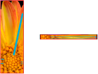
Figure 25 Partial Update
The user can switch from the watch face screen to the menu screen just by swiping to the left. The touch controller starts propagating the coordinates of the touched points and finally, scroll events are generated by the graphics library. The LVGL supports smooth scrolling/sliding between screens. When using the LVGL to perform the sliding (TWO_LAYERS_HORIZONTAL_SLIDING is set to 0), in each coordinate change the FB is redrawn to display the changes, as shown in Figure 26. However, taking advantage of the two layers that the DA1470x LCD controller supports, sliding process can be accelerated and achieve even higher FPS by moving the position of the two layers according to the coordinates provided from the graphics library (TWO_LAYERS_HORIZONTAL_SLIDING is set to 1). A full redraw of both FBs is required, each screen to the corresponding FB according to the desired layout. Meaning that the watch face will be drawn in the FB with the lowest address, and the menu will be drawn in the FB with the highest address, as shown in Figure 26. The drawing of the FBs and the display update is performed only once at the beginning of the sliding process. The sliding process, between the two screens, is achieved only by moving the start position of the two LCDC hardware layers, red and yellow rectangles of Figure 27. In the following steps, the 2 Layers sliding procedure is described:
Initialization of the sliding process
Invalidate the watch face screen to force a full FB redraw.
lv_obj_invalidate(obj);
Force an LCDC full frame update.
gdi_set_partial_update_area(LAYER_OFFSET_X + 0, LAYER_OFFSET_Y + 0,
   LAYER_OFFSET_X + lv_disp_get_hor_res(disp),
   LAYER_OFFSET_Y + lv_disp_get_ver_res(disp));
Store the default display driver callbacks for writing the internal buffer (draw_buf) to the display (flush_cb) and the timer which periodically checks the dirty areas and refreshes them (refr_timer).
flush_cb_def = *disp->driver->flush_cb;
refr_timer_def = disp->refr_timer;
Stop the display update.
disp->driver->flush_cb = NULL;
Redraw the watch face, since it was the last invalidated area.
lv_refr_now(disp);
Inform the graphics library that you are ready with the flushing.
lv_disp_flush_ready(disp->driver);
Pause the refresh timer to prevent any display update or frame buffer switch.
lv_timer_pause(disp->refr_timer);
Set the menu screen visible and invalidate the active screen.
lv_obj_move_children_by(obj, dx, 0, true);
lv_obj_invalidate(obj);
Draw the menu screen in the non-active frame buffer.
lv_refr_now(disp);
Inform the graphics library that you are ready with the flushing.
lv_disp_flush_ready(disp->driver);
Move back the position of the affected objects since scroll_by_raw handles it.
lv_obj_move_children_by(obj, -dx, 0, true);
Create a dummy timer to prevent drawing triggered from objects invalidation.
dummy_timer = lv_timer_create_basic();
disp->refr_timer = dummy_timer;
Execution of the sliding process according to the coordinates given from the touch input device.
Set the position of both Layers in x direction.
gdi_set_layer_start(HW_LCDC_LAYER_0, posXLayer0 + LAYER_OFFSET_X, posYLayer0 + LAYER_OFFSET_Y);
gdi_set_layer_start(HW_LCDC_LAYER_1, posXLayer1 + LAYER_OFFSET_X, posYLayer1 + LAYER_OFFSET_Y);
Change the frame buffer addresses of both Layers, since a manual refresh was triggered without display update.
Set the address of the video RAM of Layer 1 and make it visible.
gdi_set_layer_src(HW_LCDC_LAYER_1, layer1_addr, DEMO_RESX, DEMO_RESY, color_fmt);
gdi_set_layer_enable(HW_LCDC_LAYER_1, 1);
Set the address of the video RAM of Layer 0.
gdi_set_layer_src(HW_LCDC_LAYER_0, layer0_addr, DEMO_RESX, DEMO_RESY, color_fmt);
Trigger an LCD display update:
gdi_display_update_async(NULL, NULL);
End of the sliding process.
Clean up invalidated areas.
lv_memset_00(disp->inv_areas, sizeof(disp->inv_areas));
lv_memset_00(disp->inv_area_joined, sizeof(disp->inv_area_joined));
disp->inv_p = 0;
Re-enable display update and refresh timer callbacks.
disp->driver->flush_cb = flush_cb_def;
disp->refr_timer = refr_timer_def;
Resume the default refresh timer.
lv_timer_resume(disp->refr_timer);
Disable the visibility of Layer 1 and reset the address of the video RAM of Layer 1.
gdi_set_layer_enable(HW_LCDC_LAYER_1, 0);
gdi_set_layer_src(HW_LCDC_LAYER_1, 0, DEMO_RESX, DEMO_RESY, color_fmt);
Restore the position of Layer 0.
gdi_set_layer_start(HW_LCDC_LAYER_0, posXLayer0 + LAYER_OFFSET_X, posYLayer0 + LAYER_OFFSET_Y);
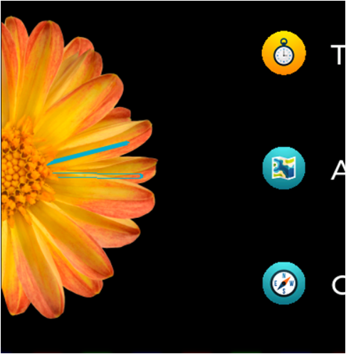
Figure 26 1 Layer Sliding from the Watch Face to the Menu Screen
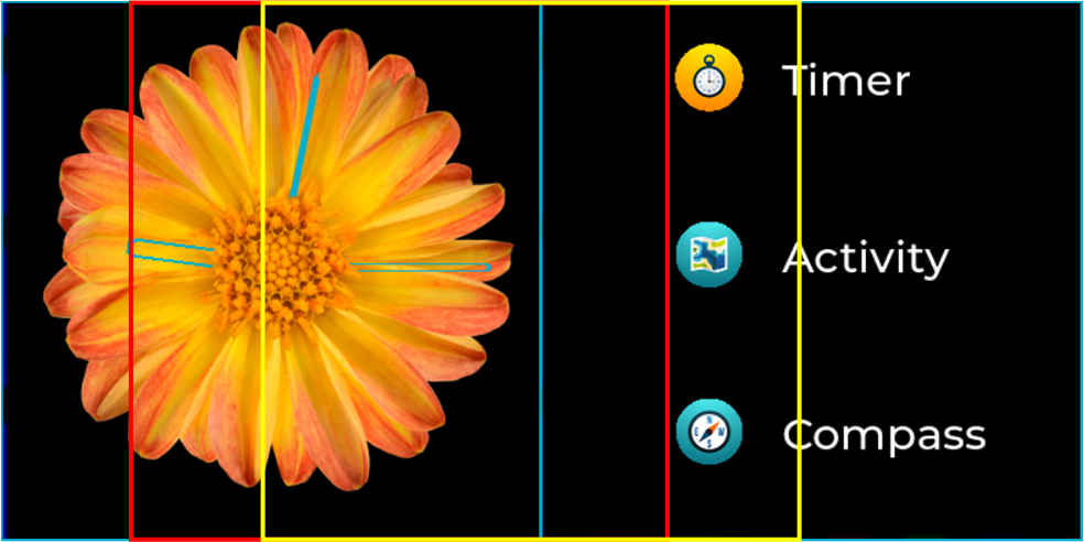
Figure 27 2 Layers Sliding from the Watch Face to the Menu Screen
Once the menu screen is visible, the user can navigate into three different screens, the timer screen, the activity screen and the compass screen. The rest of the screens are inactive. In the timer screen, the timer values are partially updated. In the activity screen, as well as in the menu screen, the user can perform vertical sliding, executed by the LVGL default scrolling process. In the compass screen, a simulation of a compass rotation, according to the received data, is demonstrated. The whole compass disk, the background image of the compass screen, is rotated. The default image rotation is performed into the location the compass image bitmap is stored, the storage QUAD SPI Flash in our example. Though, we applied an optimization to accelerate the rotation process even more, by creating a canvas in the system RAM, with the size of the compass disk image, drawing the compass bitmap into the canvas and rotate the bitmap into the system RAM (set the COMPASS_ROTATION_USES_CANVAS definition to 1).
The demo application includes a configuration file named demo.h under the ui/demo folder, in which the supported optimizations can be configured.
Macro Name |
Default Value |
Description |
|---|---|---|
FB_COLOR_FORMAT |
CF_NATIVE_RGB565 |
The FB color format. |
GDI_FB_USE_QSPI_RAM |
0 |
Define the location of the memory area allocated for the FBs. If set to 0, the FBs are allocated in the system RAM, otherwise, if set to 1, the FBs are allocated in the external PSRAM. In case of external PSRAM is used the dg_configUSE_HW_QSPI2 must be set to 1, defined in custom_config_oqspi.h. |
ORIGINAL |
1 |
Use the default processes that the LVGL provides to perform actions, like sliding or rotation. |
OPTIMAL |
2 |
Use optimizations for the sliding and the compass rotation procedures. |
NO_GPU |
3 |
Run the demonstration application without any GPU acceleration. |
SCENARIO |
OPTIMAL |
|
COMPASS_ROTATION_USES_CANVAS |
0 |
Define the location where the compass rotation will be performed. 0: Compass bitmap rotation in Flash 1: Compass bitmap rotation in SRAM with the use of a canvas. The heap size must be increased according to the size of the canvas. |
TWO_LAYERS_HORIZONTAL_SLIDING |
1 |
Define the way the horizontal |
DEMO_GUI_HEAP_SIZE |
15 * 1024 |
The size of the memory required by the graphics library. When using the canvas for compass rotation the heap size increases to 320 * 1024 |
LV_PORT_INDEV_TOUCH_QUEUE_EN |
0 |
Enable/Disable the use of a queue to store the touch data. When PERFORMANCE_METRICS is defined, the queue is used in order to execute in every run the same steps. |
11.3.3. Watch Demo Performance Measurements
After building and flashing the DA1470x-00-Debug_OQSPI_touch_simulation build configuration, the user can process the performance results. The performance measurements concern all three units, the CPU, the GPU and the LCDC, that are used from the graphics demo. Four different scenarios are evaluated:
the rotation of the clock hands,
the sliding, either horizontal to move from the watch screen to the menu screen, or vertical to browse through the menu items,
the partial update of a timer,
the rotation of the background image of a compass. The compass bitmap is either stored in the Flash or in the system RAM before rendered.
The metrics that are used for the whole demo evaluation are:
FPS: The frames per second.
Pixel Rate (in kP/sec): The number of pixels updated per second.
Frame Transfer Time (in msec): The required time for the frame to be transferred to the LCD controller.
Total Measured Rendering time (in msec): The total measured rendering time.
Total Frame Time (in msec): The sum of the frame transfer time and the total measured rendering time.
Fill (in msec): The required time to set the clip area and render a filled rectangular.
CopyBuffer: No copy operation since drawing operations are done directly to the display buffer.
BlitBitmap (in msec): The required time for BLITing an image.
RotateImage (in msec): the required time to rotate an image and draw it directly to the display buffer.
Rendering time for each GPU operation: The rendering time of each one of the above GPU operations (Fill, BlitBitmap, BlitRotate) is measured using a performance counter of GPU that counts the DAVE active cycles, instead of measuring the elapsed time from the execution of the render buffer until the actual frame flush. For small BLIT operations, GPU completes before the execution of gpu_wait_cb and therefor d2_frameflush returns immediately. Using the GPU performance counter, we may lose approximately 250 to 300 usec from our measurements, since we do not include any sw delay and we measure the actual execution time of GPU for each operation.
CPU Utilization: The amount of CPU time used to perform each scenario.
Variable |
Value |
|---|---|
Resolution |
390x390 |
FB Number |
2 |
FB Color Format |
16bit |
FB Size |
304200 |
FB Location |
System RAM |
Output Color Format |
16bit |
Resources Format |
16bit |
Resources Location |
Storage Flash |
Display refresh period (msec) |
15 |
Input device read period (msec) |
15 |
Fonts Format |
4bpp |
LCDC Interface |
QSPI |
LCDC Prefetch Level |
LVL3 (Wait until at least 116 bytes have been inserted at the LCDC FIFO) |
LCDC burst length |
16 |
GPU burst length |
8 beat |
Measured Feature |
Result |
|||
|---|---|---|---|---|
System Clock |
96 |
160 |
||
QSPI/QSPI2 Clock (MHz) |
96 |
80 |
||
LCDC Clock (MHz) |
48 |
40 |
||
Clock - Needle Rotation (partial frame update) |
FPS (1) |
10.00 |
10.00 |
|
Frame Transfer Time (msec) |
4.95 |
5.92 |
||
Pixel Rate (kP/sec) |
11.28 |
9.45 |
||
Rendering Time (msec) |
Fill |
0.64 |
0.38 |
|
BlitBitmap |
5.52 |
6.17 |
||
RotateImage |
0.61 |
0.58 |
||
Total Measured |
14.10 |
13.86 |
||
Total Frame Time (msec) (5) |
19.05 |
19.78 |
||
CPU utilization |
11% |
11% |
||
Sliding - Horizontal (2 Layers) (2) |
FPS |
67.70 |
59.20 |
|
Frame Transfer Time (msec) |
12.79 |
15.34 |
||
Pixel Rate (kP/sec) |
11.88 |
9.90 |
||
Rendering Time (msec) (3) |
Fill |
4.86 |
2.92 |
|
BlitBitmap |
12.53 |
13.83 |
||
RotateImage |
0.76 |
0.73 |
||
Total Measured |
16.00 |
12.00 |
||
Total Frame Time (msec) (5) |
28.79 |
27.34 |
||
CPU utilization |
13% |
10% |
||
Sliding - Vertical (1 Layer) (4) |
FPS |
50.70 |
57.10 |
|
Frame Transfer Time (msec) |
12.78 |
15.33 |
||
Pixel Rate (kP/sec) |
11.90 |
9.91 |
||
Rendering Time (msec) |
Fill |
3.40 |
2.09 |
|
BlitBitmap |
1.01 |
1.18 |
||
RotateImage |
0.00 |
0.00 |
||
Total Measured |
17.49 |
13.31 |
||
Total Frame Time (msec) (5) |
30.27 |
28.64 |
||
CPU utilization |
19% |
18% |
||
Timer (partial frame update) |
FPS |
66.40 |
66.20 |
|
Frame Transfer Time (msec) |
0.54 |
0.67 |
||
Pixel Rate (kP/sec) |
9.89 |
7.98 |
||
Rendering Time (msec) |
Fill |
0.05 |
0.03 |
|
BlitBitmap |
0.00 |
0.00 |
||
RotateImage |
0.00 |
0.00 |
||
Total Measured |
4.21 |
3.18 |
||
Total Frame Time (msec) (5) |
4.75 |
3.85 |
||
CPU utilization |
38% |
32% |
||
Compass Flash (6) |
FPS |
16.40 |
16.00 |
|
Frame Transfer Time (msec) |
12.78 |
15.30 |
||
Pixel Rate (kP/sec) |
11.89 |
9.93 |
||
Rendering Time (msec) |
Fill |
1.85 |
1.10 |
|
BlitBitmap |
4.69 |
5.26 |
||
RotateImage |
38.19 |
42.64 |
||
Total Measured |
53.01 |
55.81 |
||
Total Frame Time (msec) (5) |
65.79 |
71.11 |
||
CPU utilization |
17% |
14% |
||
Compass SRAM (7) |
FPS |
35.40 |
35.70 |
|
Frame Transfer Time (msec) |
12.77 |
15.31 |
||
Pixel Rate (kP/sec) |
11.90 |
9.93 |
||
Rendering Time (msec) |
Fill |
2.59 |
1.40 |
|
BlitBitmap |
4.69 |
5.24 |
||
RotateImage |
7.63 |
5.98 |
||
Total Measured |
23.31 |
19.96 |
||
Total Frame Time (msec) (5) |
36.08 |
35.27 |
||
CPU utilization |
35% |
30% |
||
Table 16 Watch Demo - Performance Measurements
Note
The FPS value in the needle rotation and timer scenarios is determined (limited) by the user interface and its update time and not from the system capabilities.
Horizontal Sliding: The 2 HW layers of the LCD controller are used to optimize horizontal sliding procedure and avoid redrawing the sliding windows in each step. The refresh timer is disabled, so the FBs are not switched and are drawn once at the beginning of the sliding. The Fill and BlitBitmap operations are executed only once. The RotateImage measurement is caught due to the preparation of both FBs (redraw of the watch screen into the FB). Measurements are captured for one complete sliding from the rightmost to the leftmost window.
Rendering time is measured for filling the active rectangular and drawing the FB that will be used from the 2 Layers of the LCD controller only at the first frame. After that no other rendering action is performed and sliding is done by the HW layers of the LCD controller.
Vertical Sliding: LVGL graphics library performs vertical sliding. The FB is redrawn at each step according to the current window position. The samples reflect 2 vertical sliding periods, from top to bottom and back on top.
For applications that use one FB, Total Frame time and FPS will be reduced since rendering and transfer operations are performed linear. In scenarios that make use of two FBs, transfer and drawing operations are performed in parallel.
Compass image rotation is performed at Storage Flash, where the compass resource is located. Compass rotation with 1 degree step, starting from 0 degrees until 360 degrees.
Compass image rotation is performed in SRAM. The compass resource image is copied to a canvas object located at SRAM, and the rotation is performed on the canvas object. Compass rotation with 1 degree step, starting from 0 degrees until 360 degrees.