9. Graphics Display Interface (GDI)
The GDI implementation is delivered along with the LVGL graphics library. This library is designed to provide an efficient, processor- and display controller-independent graphical user interface for any application that operates with a graphical display.
This section aims to provide an in-depth analysis of the GDI layer, part of the displays support. The GDI entity is an intermediate layer that links the graphics library used, in our case this is the LVGL solution, with the LCDC adapters. A display-specific configuration file determines the behavior of the GDI layer and because of that, there is no need for the developer to modify the GDI layer in case a different display should be supported. To facilitate users, the GDI solution comes with several configuration files that support some of the most commonly used LCD displays. However, and in case a different display should be employed, the user should be able to support their displays by creating the appropriate configuration file. A detailed explanation on the contents of a configuration file is given later in this document.
Part No |
Resolution |
Interface |
Controller |
|---|---|---|---|
DT280QV10CT |
240x320 |
SPI4 |
ILI9341 |
LPM012M134B |
240x240 |
JDI Parallel |
|
LPM013M091A |
320x300 |
SPI4 |
NT35350 |
LPM010M297B |
208x208 |
JDI SPI |
|
NHD43480272EFASXN |
480x272 |
DPI |
ST7282T2 |
MCT024L6W240320PML |
240x320 |
SPI4 |
ILI9341 |
PSP27801 |
96x96 |
SPI4 |
SSD1351 |
T1D3BP006 |
240x240 |
SPI3 SPI4 DUAL SPI |
ST7789V2 |
T1D54BP002 |
240x240 |
SPI3 |
ST7789V2 |
LS013B7DH06 |
128x128 |
Sharp SPI |
|
LS013B7DH03 |
128x128 |
Sharp SPI |
|
MRB3973 |
800x480 |
DBI-B |
NT35510 |
E120A390QSR |
390x390 |
SPI3 SPI4 DUAL SPI QUAD SPI |
RM69091 |
9.1. LCD Controller
The LCD controller is used to compose multiple graphics and video layers by improving image quality, support composition features and a wide range of display interfaces. It is designed to offload the GPU or the CPU, and minimize the memory bandwidth. The 2 HW layers can be scaled, clipped, positioned and composed on the final display by overlaying video, subtitles, graphics, cursors or application windows, with or without transparency. The LCDC is controlled by the configuration register. The timing generator is programmable, and the data are fetched for each layer by a dedicated DMA engine. During blending process, a translucent foreground color is combined with a background color resulting to a new blended color. The output depends on the target screen and can be formatted in different types and color formats.
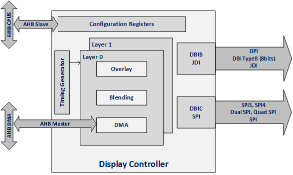
Figure 4 LCDC Block Diagram
9.1.1. HW Features
Up to two layers with blending capabilities
Alpha blending
Global Gamma Correction (LUT-based) support
Dithering and Gamma Correction support
AHB 32-bit Master interface with internal DMA engine
Various blending modes for each layer
Simple
Clear
Source
Destination
Input color formats:
RGBA-8888, ARGB-8888, ABGR-8888, BGRA-8888, RGB-888, RGBA-5551, RGB-565 and RGB-332
Output interfaces:
MIPI DPI-2, 6-bit parallel interface (RGB-222) with HSYNC/VSYNC signaling
MIPI DBI Type-B 8-bit data parallel interface
JDI parallel interface
3/4-wire SPI serial interface
Dual and Quad SPI serial interface
Read operation supported from LCD (DBI-B, DBI-C, QSPI).
Interface |
Read Capability |
RGB111 |
RGB222 |
RGB332 |
RGB444 |
RGB565 |
RGB666 |
RGB888 |
|---|---|---|---|---|---|---|---|---|
DPI (6bit) |
✓ |
|||||||
DBI-B (8bit) |
✓ |
✓ |
✓ |
✓ |
✓ |
✓ |
||
DBI-C (SPI 3/4) |
✓ |
✓ |
✓ |
✓ |
✓ |
✓ |
✓ |
|
Dual SPI |
✓ |
✓ |
✓ |
✓ |
||||
Quad SPI |
✓ |
✓ |
✓ |
✓ |
✓ |
|||
JDI Parallel |
✓ |
|||||||
JDI SPI / Sharp SPI |
✓ |
9.1.2. Usage
9.1.2.1. Initialization
During the initialization phase, the user should open the LCD device, properly configure the controller interface IOs, and initialize the drivers associated with the controller. After the completion of the initialization phase, the device should close.
//Open device
ad_lcdc_handle_t dev = ad_lcdc_open(&e120a390qsr_cfg);
OS_ASSERT(dev != NULL);

//Execute commands
ad_lcdc_execute_cmds(dev, screen_init_cmds, sizeof(screen_init_cmds));

//Close device
OS_TICK_TIME timeout = OS_GET_TICK_COUNT() +
OS_MS_2_TICKS(DEV_CLOSE_TIMEOUT_MS);
while(ad_lcdc_close(dev, false) != AD_LCDC_ERROR_NONE) {
    if (timeout <= OS_GET_TICK_COUNT()) {
        ad_lcdc_close(dev, true);
        break;
    }
OS_DELAY(1);
}
The input device of the LVGL is also initialized and updated using a timer which periodically reads the input device. The LVGL will be described thoroughly in the next chapter.
9.1.2.2. Layer Setup and Transfer
The layer setup is independent from the frame transfer to the LCD, since LCD has 2 layers. If the layer properties do not change, there is no need to setup the layer at every frame transferred. After the layer setup is complete, a screen contents update with the layer parameters is performed.
//Open device

//Optionally setup layer(s)
ad_lcdc_setup_layer(HW_LCDC_LAYER_0, &layer_bg);
ad_lcdc_setup_layer(HW_LCDC_LAYER_1, &layer_fg);

//Transfer frame
ad_lcdc_draw_screen_async(dev, frame_update_cb, gdi);
if (OS_EVENT_SIGNALED != OS_EVENT_WAIT(draw_event, OS_MS_2_TICKS(DEV_DRAW_TIMEOUT_MS))) {
    //Handle error
}

//Close device
9.2. GDI File Structure
This section briefly describes the file tree of the delivered GDI implementation. The GDI layer has two software components. The src sub-folder hosts the implementation of the GDI layer and the inc folder includes a number of configuration files that support common LCD displays for out-of-the-box use.

Figure 5 GDI File Structure
9.3. GDI Configurations
Typical GDI configurations include the amount of memory allocated, the amount of memory used by the graphics library, as well as the color format used to represent pixel data. In specific, LVGL requires some heap memory for its internal operations as well as memory (frame buffers) used to accommodate intermediate pixel data and to display the image, in some specific cases. The size of a FB depends on the display resolution and color depth. For instance, a display of 390x390 resolution and RGB565 color depth requires a frame buffer capable of accommodating 390x390x2 = 304,200 bytes. The memory that the graphics library allocates can be part of either the system RAM or an external QSPI RAM. To facilitate users further, there is the possibility to put heap memory and FBs in different memory locations. By default, all memory allocated by the graphics library is part of the system RAM.
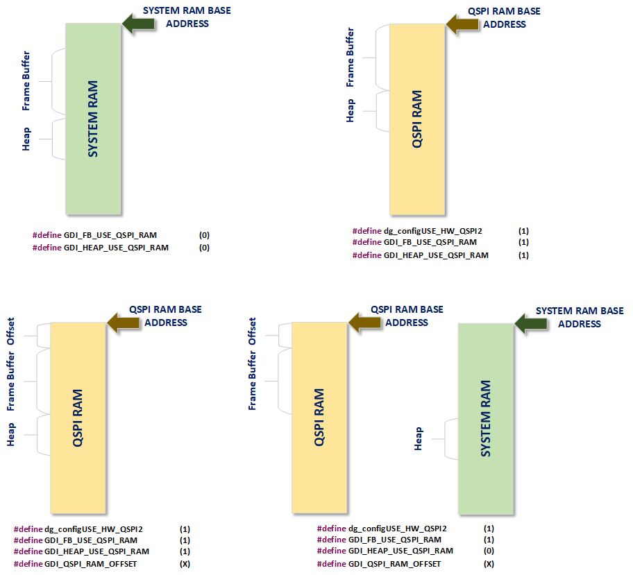
Figure 6 Memory Layout Schemes
For color format, there are two different configurations to be taken into consideration. The first configuration concerns the color depth used by the graphics library to process the various pixel data with the help of the frame buffers (input color format). The second configuration concerns the output color depth used by the LCD controller (output color format). The LCD controller can perform color conversions from one format to another. For instance, and as illustrated in Figure 7, the Frame Buffer can have RGB565 color mode and the output can be converted on-the-fly and with zero latency by the LCD controller to RGB666 color mode.

Figure 7 LCDC Color Conversion Scheme
Macro Name |
Default Value |
Description |
|---|---|---|
GDI_TOUCH_INTERFACE |
GDI_TOUCH_INTERFACE_I2C |
The serial interface required to communicate to the touch controller. Currently, only the I2C serial interfaces is supported. |
GDI_CONSOLE_LOG |
0 |
If set to 1, log messages will be printed in the console output. Otherwise, log messages are not printed. Def values: 0 : DA1470x-00-Debug_OQSPI_demo 1 : DA1470x-00-Debug_OQSPI_touch_simulation |
GDI_NO_PREALLOC |
0 |
If set to 0, the FBs and the heap is allocated during the initialization of the GDI layer. If set to 1, allocation must be handled by the user. |
GDI_FB_USE_QSPI_RAM |
0 |
Define the location of the memory area allocated for the FBs. If set to 0, the FBs are allocated in the system RAM, otherwise, if set to 1, the FBs are allocated in the external PSRAM. In case of external PSRAM is used the dg_configUSE_HW_QSPI2 must be set to 1, defined in custom_config_oqspi.h. |
GDI_HEAP_USE_QSPI_RAM |
0 |
If set to 0, the amount of heap memory is allocated in the system RAM. Otherwise, the external PSRAM is used. It’s essential that dg_configUSE_HW_QSPI2 is set to 1. Otherwise, an error message will show on compile time. |
GDI_QSPI_RAM_OFFSET |
0 |
Offset, expressed in bytes, added to the base address of PSRAM before allocating memory. If not defined, memory allocation will start at the base address of QSPI2 controller. |
GDI_LCDC_FIFO_PREFETCH_LVL |
HW_LCDC_FIFO_PREFETCH_LVL_3 |
Number of bytes that should be received in the internal FIFO of the LCD controller, by the dedicated DMA, before the controller starts outputting them towards the target display. Valid values can be selected from the HW_LCDC_FIFO_PREFETCH_LVL enumeration structure. Note that, the chosen value depends on the physical location of the allocated frame buffers. Enabling the pre-fetch feature is strongly recommended when the frame buffers reside in QSPI RAM. In doing so, the increased latency imposed by the communication itself (bus) is compensated. |
GDI_USE_OS_TIMER |
0 |
If set to 1, timestamp operations are based on OS timers. Otherwise, timestamp operations are based on the lower power (lp) clock used. |
GDI_USE_CONTINUOUS_MODE |
0 |
If set to 1, the continuous mode of the LCD controller is enabled. In this mode, the LCD controller continuously sends pixel data to the display, even if a single frame image is to be sent. This operation mode is useful when the target display does not feature any kind of build-in memory i.e. GRAM or memory-in-pixel, used to store its pixel data. The displays that can support continuous mode are those that support DPI or JDI Parallel interfaces. |
GDI_MULTIPLEX_TOUCH_DISPLAY |
0 |
This macro must be set to 1, if the display and touch controllers are connected on the same bus, e.g. SPI. |
GDI_SINGLE_FB_NUM |
2 |
Number of FBs allocated for the various drawing operations. When using more than one FB, the display always shows a screen which is already completely rendered, even if a drawing operation is in progress. Note that, the LVGL can handle the multiple buffers automatically. |
GDI_FB_COLOR_FORMAT |
CF_NATIVE_RGB565 |
The color format used by the graphics library. By design, four input color formats are supported by the GDI layer, that is RGB332, RGB565, RGBA8888 and ARGB8888. |
GDI_FB_RESX |
390 |
Horizontal resolution of the LCD |
GDI_FB_RESY |
390 |
Vertical resolution of the LCD |
GDI_DISP_COLOR |
HW_LCDC_OCM_8RGB565 |
Output color mode format of the layer. Valid values can be selected from HW_LCDC_OUTPUT_COLOR_MODE enumeration structure. |
GDI_DISP_RESX |
390 |
Horizontal resolution of layer in pixels |
GDI_DISP_RESY |
390 |
Vertical resolution of layer in pixels |
9.3.1. Usage
9.3.1.1. Display Interface Configuration
This section analyses the typical structure of a configuration file. It provides a thorough description of the default LCD model, which is E120A390QSR, as well as peculiarities encountered on some LCD interfaces.
Initially, the configuration file should include all configurations of the LCD controller, which are mainly split into two structures. The first structure concerns the driver of the target display. Typical settings are the LCD interface, output color format, LCD interface speed, the resolution of the target display as well as various timing parameters required to communicate to the controller of the display. The second structure deals with the I/O pins used by the LCD controller to output pixel data as well as timing signals. This structure is put in a separate source file, named platform_devices.c. To facilitate the user, a copy of the LCD-related I/O pins is found on top of each configuration file.
static GDI_DRV_CONF_ATTR ad_lcdc_driver_conf_t e120a390qsr_drv = {
#if E120A390QSR_SPI3
    .hw_init.phy_type = HW_LCDC_PHY_MIPI_SPI3,
#elif E120A390QSR_SPI4
    .hw_init.phy_type = HW_LCDC_PHY_MIPI_SPI4,
#elif E120A390QSR_DSPI
    .hw_init.phy_type = HW_LCDC_PHY_DUAL_SPI,
#elif E120A390QSR_QSPI
    .hw_init.phy_type = HW_LCDC_PHY_QUAD_SPI,
#endif

    .hw_init.format = GDI_DISP_COLOR,
    .hw_init.resx = GDI_DISP_RESX,
    .hw_init.resy = GDI_DISP_RESY,
    .hw_init.cfg_extra_flags = 0,
    .hw_init.mode = HW_LCDC_MODE_DISABLE,
#if E120A390QSR_SPI3 || E120A390QSR_SPI4 || E120A390QSR_DSPI || E120A390QSR_QSPI
    .hw_init.write_freq = LCDC_FREQ_48MHz,  // Max. @50MHz
    .hw_init.read_freq = LCDC_FREQ_3_2MHz,  // Max. @3.3MHz
#endif

#if E120A390QSR_SPI3 || E120A390QSR_SPI4
    .hw_init.iface_conf.spi.si_on_so = true,
#elif E120A390QSR_DSPI
    .hw_init.iface_conf.dspi.option = !E120A390QSR_DSPI_2P3T2 ? HW_LCDC_DSPI_OPT_1P1T2 : HW_LCDC_DSPI_OPT_2P3T2,
    .hw_init.iface_conf.dspi.spi3 = E120A390QSR_DSPI_SPI3,
    .hw_init.iface_conf.dspi.si_on_so = true,
#elif E120A390QSR_QSPI
    .hw_init.iface_conf.qspi.sss_write_cmd = 0x02,
    .hw_init.iface_conf.qspi.sss_read_cmd = 0x03,
    .hw_init.iface_conf.qspi.ssq_write_cmd = 0x32,
    .hw_init.iface_conf.qspi.cmd_width = HW_LCDC_CMD_WIDTH_24,
    .hw_init.iface_conf.qspi.si_on_so = true,
#endif

    .ext_clk = HW_LCDC_EXT_CLK_OFF,
    .te_enable = E120A390QSR_TE_ENABLE ? true : false,
    .te_mode = HW_LCDC_TE_POL_HIGH,
};

static const ad_lcdc_controller_conf_t e120a390qsr_cfg = {
    .io = &e120a390qsr_io,
    .drv = &e120a390qsr_drv,
};
Note
There is a minimum of timing parameters required for the correct operation of the LCD controller; even if this is not required by the target display model and LCD interface.
Note
If the Tearing Effect (TE) is enabled, then make sure that the target display supports that functionality.
Next, the configuration file should determine the behavior of the LCD controller/GDI for various display-related operations. For instance:
Power on the display. Typically, this step involves enabling the backlight and/or the EN signal of the display.
/*
  * Define LCDC commands that should be executed to power ON the target display.
  */
static const uint8_t screen_power_on_cmds[] = {......}
;
Initialize the display. Typically, this step involves a hardware and software reset, setting the color mode and frame rate, enable/disable the tearing effect of the display as well as various display-specific configurations.
static const uint8_t screen_init_cmds[] = {
    LCDC_GPIO_SET_ACTIVE(E120A390QSR_PWR_ON_PORT, E120A390QSR_PWR_ON_PIN),
    LCDC_DELAY_MS(10),

#if E120A390QSR_SPI3 || (E120A390QSR_DSPI && E120A390QSR_DSPI_SPI3)
    //IM[1:0] = 00 (SPI3)
    LCDC_GPIO_SET_INACTIVE(E120A390QSR_IM0_PORT, E120A390QSR_IM0_PIN),
    LCDC_GPIO_SET_INACTIVE(E120A390QSR_IM1_PORT, E120A390QSR_IM1_PIN),
#elif E120A390QSR_SPI4 || (E120A390QSR_DSPI && !E120A390QSR_DSPI_SPI3)
    //IM[1:0] = 01 (SPI4)
    LCDC_GPIO_SET_ACTIVE(E120A390QSR_IM0_PORT, E120A390QSR_IM0_PIN),
    LCDC_GPIO_SET_INACTIVE(E120A390QSR_IM1_PORT, E120A390QSR_IM1_PIN),
#elif E120A390QSR_QSPI
    //IM[1:0] = 10 (QSPI)
    LCDC_GPIO_SET_INACTIVE(E120A390QSR_IM0_PORT, E120A390QSR_IM0_PIN),
    LCDC_GPIO_SET_ACTIVE(E120A390QSR_IM1_PORT, E120A390QSR_IM1_PIN),
#endif

    LCDC_GPIO_SET_INACTIVE(E120A390QSR_RST_PORT, E120A390QSR_RST_PIN),
    LCDC_DELAY_MS(50),
    LCDC_GPIO_SET_ACTIVE(E120A390QSR_RST_PORT, E120A390QSR_RST_PIN),
    LCDC_DELAY_MS(120),

    LCDC_MIPI_CMD_DATA(0xFE, 0x01),

    LCDC_MIPI_CMD_DATA(0x04, 0xA0),

    LCDC_MIPI_CMD_DATA(0xFE, 0x01),

    LCDC_MIPI_CMD_DATA(0x6A, 0x00),  //! Normal ELVSS = -2.4V
    LCDC_MIPI_CMD_DATA(0xAB, 0x00),  //! HBM ELVSS = -2.4V

    LCDC_MIPI_CMD_DATA(0xFE, 0x00),

    //! Enable SPI interface write RAM, configure Dual SPI mode
    LCDC_MIPI_CMD_DATA(0xC4, 0x80 | (E120A390QSR_DSPI ? 0x01 : 0x00)
                                  | (!E120A390QSR_DSPI_2P3T2 ? 0x20 : 0x30)),
    LCDC_MIPI_CMD_DATA(HW_LCDC_MIPI_DCS_WRITE_CONTROL_DISPLAY, 0x20), //! dimming
    LCDC_MIPI_CMD_DATA(HW_LCDC_MIPI_DCS_SET_DISPLAY_BRIGHTNESS, 0xFF),

    LCDC_MIPI_SET_POSITION(GDI_DISP_OFFSETX, GDI_DISP_OFFSETY,
            GDI_DISP_RESX + GDI_DISP_OFFSETX - 1,
            GDI_DISP_RESY + GDI_DISP_OFFSETY - 1),
    LCDC_MIPI_SET_MODE(
#if E120A390QSR_SPI3 || E120A390QSR_SPI4
            GDI_DISP_COLOR == HW_LCDC_OCM_8RGB111_1 ? E120A390QSR_PIXEL_FORMAT_RGB111 :
#if (DEVICE_FAMILY == DA1470X)
            GDI_DISP_COLOR == HW_LCDC_OCM_8RGB111_3 ? E120A390QSR_PIXEL_FORMAT_RGB111 :
#endif
            GDI_DISP_COLOR == HW_LCDC_OCM_8RGB332   ? E120A390QSR_PIXEL_FORMAT_RGB332 :
#elif !(E120A390QSR_DSPI && E120A390QSR_DSPI_2P3T2)
            GDI_DISP_COLOR == HW_LCDC_OCM_8RGB565   ? E120A390QSR_PIXEL_FORMAT_RGB565 :
#endif
            GDI_DISP_COLOR == HW_LCDC_OCM_8RGB666   ? E120A390QSR_PIXEL_FORMAT_RGB666 :
                                                      E120A390QSR_PIXEL_FORMAT_RGB888),
#if (DEVICE_FAMILY == DA1470X)
#if E120A390QSR_SPI3 || E120A390QSR_SPI4
    LCDC_MIPI_CMD_DATA(0x80, GDI_DISP_COLOR == HW_LCDC_OCM_8RGB111_3 ? E120A390QSR_PIXEL_FORMAT_OPT_RGB111_3 :
                                                                        E120A390QSR_PIXEL_FORMAT_OPT_RGB111_1),
#endif
#endif

#if E120A390QSR_TE_ENABLE
    LCDC_MIPI_SET_TEAR_ON(0x00),
#else
    LCDC_MIPI_CMD_DATA(HW_LCDC_MIPI_DCS_SET_TEAR_OFF),
#endif
};
Enable the display. Typically, this step involves exiting the display from low power mode and configure for active mode.
static const uint8_t screen_enable_cmds[] = {
    LCDC_MIPI_CMD_DATA(HW_LCDC_MIPI_DCS_EXIT_SLEEP_MODE),
    LCDC_DELAY_MS(120),
    LCDC_MIPI_CMD_DATA(HW_LCDC_MIPI_DCS_SET_DISPLAY_ON),
    LCDC_DELAY_MS(50),
};
Note
The display is enabled during the GDI instance initialization, by calling gdi_setup_screen() function. This triggers the execution of the LCDC commands written in screen_enable_cmds[].
9.3.1.2. Display Initialization
The display initialization is done during the GDI instance initialization, by calling the gdi_setup_screen() function. The call of gdi_init() function initializes the GDI instance, allocates the required memory for the FB and sets the default background color. Finally, triggers the execution of the command sequence for the power on, the initialization and the enable of the display, along with the initialization of the touch controller. The initialization sequence is shown at Figure 8.
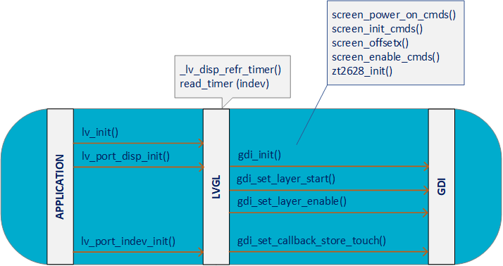
Figure 8 Display Initialization Sequence Diagram
9.3.1.3. Display Update
The UI changes trigger the execution of several draw operations, either periodically by the LVGL refresh timer or on demand. The steps, as shown at Figure 9, will finally end up to a display update with the FB new content. The user should set the appropriate coordinates of the area of the LCD that will be updated. It can be either the whole screen or a part of it. The LCDC layer should be setup, although in cases where the default layer properties do not change this step is optional. The starting offset of the layer is required before the asynchronous display update function is called.
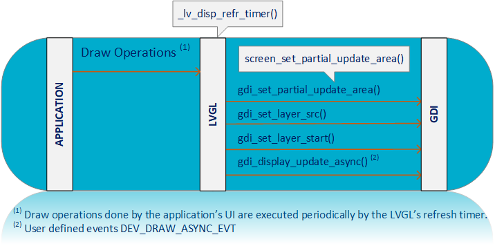
Figure 9 Display Update Sequence Diagram
9.4. Adding Support for New Displays
This section lists the required steps to add support for new display models (not supported by default). Do the following steps:
In /config/custom_config_xxx.h, declare a macro used to select the target display. For instance:
#define dg_configUSE_DT280QV10CT   ( 0 )
#define dg_configUSE_MRB3973_DBIB  ( 0 )
#define dg_configUSE_E120A390QSR   ( 0 )

#define dg_configUSE_MY_CUSTOM_LCD ( 1 )
Note
If the display supports touch functionality, declare a macro used to select the target touch controller.
In /config/peripheral_setup.h, declare macros for the LCD I/O pins used to connect/communicate to the target display. For instance:
#if dg_configUSE_MY_CUSTOM_LCD
    /*
    * Add macro definitions that reflect the LCD I/O pins of the target display.
    */
    #define MY_CUSTOM_LCD_SDI_PORT HW_GPIO_PORT_1
    #define MY_CUSTOM_LCD_SDI_PIN  HW_GPIO_PIN_13
    #define MY_CUSTOM_LCD_SCL_PORT HW_GPIO_PORT_1
    #define MY_CUSTOM_LCD_SCL_PIN  HW_GPIO_PIN_17
#endif
Note
If the display supports touch functionality, declare macros for the I/O pins used to connect and communicate to the target touch controller.
In platform_devices.c, declare all I/O pins that the LCD controller needs to communicate with the target display. For instance:
#elif dg_configUSE_MY_CUSTOM_LCD
static const ad_io_conf_t my_custom_lcd_gpio_cfg[] = {
        { MY_CUSTOM_LCD_SCL_PORT, MY_CUSTOM_LCD_SCL_PIN,
            { HW_GPIO_MODE_OUTPUT, HW_GPIO_FUNC_LCD_SPI_CLK, true },
            { HW_GPIO_MODE_OUTPUT, HW_GPIO_FUNC_GPIO, true }},
        { MY_CUSTOM_LCD_SDI_PORT, MY_CUSTOM_LCD_SDI_PIN,
            { HW_GPIO_MODE_OUTPUT, HW_GPIO_FUNC_LCD_SPI_DO, true },
            { HW_GPIO_MODE_OUTPUT, HW_GPIO_FUNC_GPIO, true }},

};

const ad_lcdc_io_conf_t my_custom_lcd_io = {
     .voltage_level = HW_GPIO_POWER_VDD1V8P,
     .io_cnt = sizeof(my_custom_lcd_gpio_cfg) / sizeof(my_custom_lcd_gpio_cfg[0]),
     .io_list = my_custom_lcd_gpio_cfg,
};
#endif
Note
If the display supports touch functionality, declare all I/O pins that the serial controller (e.g. I2C) needs to communicate with the target touch controller.
In /config/platform_devices.h, declare an external variable that has the previously defined structure (I/O pins configurations). For instance:
#if dg_configLCDC_ADAPTER
#if dg_configUSE_MRB3973_DBIB
    extern const ad_lcdc_io_conf_t mrb3973_dbib_io;
#elif dg_configUSE_E120A390QSR
    extern const ad_lcdc_io_conf_t e120a390qsr_io;


#elif dg_configUSE_MY_CUSTOM_LCD
    extern const ad_lcdc_io_conf_t my_custom_lcd_io;
#endif
#endif /* dg_configLCDC_ADAPTER */
Note
If the display supports touch functionality, declare an external variable that has the previously defined structure that holds the I/O pins for connecting to the touch controller.
In main.c, declare the default LCD controller’s I/O pins configurations. These configurations are applied when the device initializes and should be put in prvSetupHardware(). For instance:
static void prvSetupHardware( void ) {


#if dg_configLCDC_ADAPTER
#if dg_configUSE_MRB3973_DBIB
    ad_lcdc_io_config(&mrb3973_dbib_io, AD_IO_CONF_OFF);
#elif dg_configUSE_E120A390QSR
    ad_lcdc_io_config(&e120a390qsr_io, AD_IO_CONF_OFF);


#elif dg_configUSE_MY_CUSTOM_LCD
    ad_lcdc_io_config(&my_custom_lcd_io, AD_IO_CONF_OFF);
#endif
#endif /* dg_configLCDC_ADAPTER */
}
Note
If the display supports touch functionality, declare the default serial controller’s I/O pins configurations.
Create a configuration file for the target display. To do so, make a copy of an existing configuration file and make the necessary changes to support the target display. For instance:
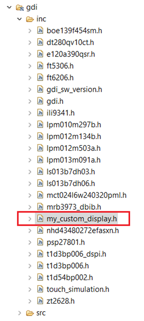
Figure 10 Creating New Display Configuration File
In /ui/gdi_config.h, declare the configuration file to use once the target display is selected. For instance:
#if dg_configUSE_MRB3973_DBIB
    #include " mrb3973_dbib.h "
#elif dg_configUSE_E1394AA65A
    #include "e1394aa65a.h"


#elif dg_configUSE_MY_CUSTOM_LCD
    #include "my_custom_display.h"
#endif
9.5. Adding Support for Touch Operations
This section explains all the steps required to enable touch operations on the E120A390QSR LCD shield.
In the custom configuration file of the demo (custom_config_oqspi.h), enable the macro that includes the zt2628.h touch configuration file of the ZT2628 touch controller,
#define dg_configUSE_ZT2628 ( 1 )This configuration file, enables the touch support, defines the interface required to communicate to the target touch controller.
#define GDI_TOUCH_ENABLE (1)
#define GDI_TOUCH_INTERFACE (GDI_TOUCH_INTERFACE_I2C)
Note
To enable the touch controller only step 1 is needed.
The configuration file includes configurations of the selected serial controller (e.g. I2C), which are mainly split into two structures. The first structure concerns the driver of the target touch controller and the second structure deals with the I/O pins used to physically connect to the touch controller.
/* I2C driver configurations */
static const ad_i2c_driver_conf_t zt2628_drv = {
    I2C_DEFAULT_CLK_CFG,
    .i2c.speed = HW_I2C_SPEED_FAST,
    .i2c.mode = HW_I2C_MODE_MASTER,
    .i2c.addr_mode = HW_I2C_ADDRESSING_7B,
    .i2c.address = ZT2628_I2C_ADDRESS,
    .dma_channel = HW_DMA_CHANNEL_2
};

/* I2C controller configurations */
static const ad_i2c_controller_conf_t zt2628_cfg = {
    .id = HW_I2C1,
    .drv = &zt2628_drv,
    .io = &zt2628_io
};
The latter, is put in a separate source file, named platform_devices.c.
#if dg_configUSE_ZT2628
const ad_i2c_io_conf_t zt2628_io = {
    { ZT2628_SCL_PORT, ZT2628_SCL_PIN,
        { HW_GPIO_MODE_OUTPUT_OPEN_DRAIN, HW_GPIO_FUNC_I2C_SCL, false },
        { HW_GPIO_MODE_INPUT, HW_GPIO_FUNC_GPIO, true }},
    { ZT2628_SDA_PORT, ZT2628_SDA_PIN,
        { HW_GPIO_MODE_OUTPUT_OPEN_DRAIN, HW_GPIO_FUNC_I2C_SDA, false },
        { HW_GPIO_MODE_INPUT, HW_GPIO_FUNC_GPIO, true }},
    .voltage_level = HW_GPIO_POWER_V33
};
#endif /* dg_configUSE_ZT2628 */
In main.c, the default touch controller’s I/O pins configurations should be declared and configured. These configurations are applied when the device initializes and should be put in prvSetupHardware().
static void prvSetupHardware( void )
{

    #elif dg_configUSE_ZT2628
        ad_i2c_io_config(HW_I2C1, &zt2628_io, AD_IO_CONF_OFF);
    #endif

}
Then, a user-defined callback function that initializes the touch controller should be defined. This routine is called the very first time GDI is initialized.
/* User-defined routine used by GDI to initialize the target touch controller \*/
__STATIC_INLINE void zt2628_init(void *dev)
{
    /* Enable I2C pullups */
    /* Exit from reset */

    /*
    * power_sequence
    */

    /* send power sequence(vendor cmd enable) */
    /* read chip code */
    /* send power sequence(intn clear) */
    /* send power sequence(nvm init) */
    /* send power sequence(program start) */
    /*

    /*
    *init_touch
    */

    /* write reset command */
    /* cover_set */
    /* read garbage data */
}
The next piece of information deals with the routine that performs the actual touch read operations. This routine is called by GDI, following a valid touch event, to read and store touch data.
/* User-defined routine used by GDI to read touch events */
__STATIC_INLINE void zt2628_read_event(void *dev, gdi_touch_data_t *touch_data) {

    uint8_t status;
    uint16_t x, y;
    uint16_t addr[] = { 0 };
    z2628_point_info_t touch_info;

    /* read point info */
    addr[0] = ZT2628_POINT_STATUS;
    ad_i2c_write_read(dev, (uint8_t *)addr, sizeof(addr), (uint8_t *)&touch_info,
        sizeof(touch_info), HW_I2C_F_ADD_STOP);

    if ((touch_info.status & ZT2628_INT_MUST_ZERO) ||(touch_info.status == 0x1)) {
        printf("abnormal point info read\r\n");
    }

    addr[0] = ZT2628_CLEAR_INT_STATUS_CMD;
    ad_i2c_write(dev, (uint8_t *)addr, sizeof(addr), HW_I2C_F_ADD_STOP);

    if (touch_info.finger_cnt > 1) {
        printf("finger count %d\r\n", touch_info.finger_cnt);
    }

    status = touch_info.coord.status;
    x = touch_info.coord.x;
    y = touch_info.coord.y;

    touch_data->pressed = 0;
    if (status & ZT2628_POINT_STATUS_EXIST) {
        if (status & ZT2628_POINT_STATUS_DOWN) {
            touch_data->pressed = 1;
        }
        else if (status & ZT2628_POINT_STATUS_MOVE) {
            touch_data->pressed = 1;
        }
    }

    /* Convert touch data to display coordinates */
    touch_data->x = zt2628_map_touch_to_display(x, 0, GDI_DISP_RESX, 0, GDI_DISP_RESX);
    touch_data->y = zt2628_map_touch_to_display(y, 0, GDI_DISP_RESY, 0, GDI_DISP_RESY);
}
The last part, in terms of configuration information, concerns the way GDI is notified once a valid touch event is generated by the touch controller. Typically, a touch controller toggles a pin if a valid touch is detected. This pin should be connected by the user to the DA1470x WKUP controller, so the system can react on the touch event. In the current GDI implementation, and once the WKUP controller is up and running, a call to the gdi_touch_event() routine should be performed following a touch event. Note that this function can be called either directly within an Interrupt Service Routine (ISR) or within an RTOS task.
/* WKUP P0 interrupt handler (ISR) */
static void _wkup_gpio_cb(void) {
    uint32_t status;

    /* Clear the WKUP interrupt flag!!! (mandatory) */
    hw_wkup_reset_key_interrupt();

    /*
     * Get port status of the last wake-up event.
     *
     * \\note: The status is returned as BITMASK, meaning that each bit reflects
     * the corresponding pin state.
     */
    status = hw_wkup_get_gpio_status(TOUCH_INT_PORT);

    /*
    * Clear the interrupt latch status!!! (mandatory).
    */
    hw_wkup_clear_gpio_status(TOUCH_INT_PORT, status);

    /*
    * If interrupt is produced by the touch controller, then notify the GDI task.
    */
    if (status & TOUCH_INT_PIN_MASK) {
        gdi_touch_event();
    }
    else {
        /* Otherwise, notify other tasks (if needed) */
    }
}
After the hardware configuration is complete, we need to register an input device in graphics library level. Initialize the touchpad device, touchpad_init(), by setting the GDI callback function which is used to store the read touch events into the graphics buffers. After the registration of the display, an input device driver has to be initialized. The user should set the type of the input device driver and the function pointer callback for reading the input device data. The registration of the input device driver creates a timer that periodically reads the input device.
static lv_indev_drv_t indev_touchpad_drv;

/*Initialize your touchpad if you have*/
touchpad_init();

/*Register a touchpad input device*/
lv_indev_drv_init(&indev_touchpad_drv);
indev_touchpad_drv.type = LV_INDEV_TYPE_POINTER;
indev_touchpad_drv.read_cb = touchpad_read;
indev_touchpad = lv_indev_drv_register(&indev_touchpad_drv);
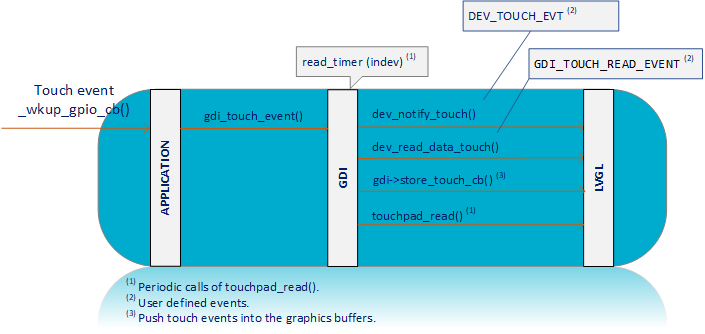
Figure 11 Read Touch Event Sequence Diagram