6. DA14585/586 Software Installation
This section describes the installation procedure for the drivers, the configuration of the serial port, and all necessary steps to verify the connection with the PC. It also provides solutions to problems that may occur.
6.1. Requirements of the Development PC
For proper evaluation and application development using the DA14585/586 SoC and the Basic Development Kit, an external host is required. This external host must have a Windows already installed and USB ports as described in Section Section 4.
6.2. Driver Installation
On first connection to a host PC running Microsoft Windows, the system will detect several devices and will automatically install all necessary drivers. If the system is configured to use Windows Update, this may take several minutes to complete.
When the driver installation is complete, the system displays a window similar to the one presented in Figure 11.
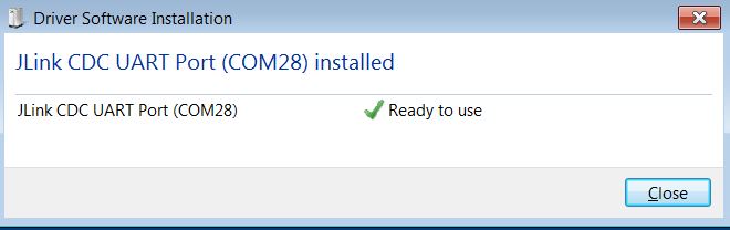
Figure 11 Windows Driver Installation
There is one virtual COM port created by the Windows driver. This COM port (COM28 in this example) provides a UART interface between the PC and the DA14585/586 device. For current measurement please refer to the Figure 38 in Appendix C.
You can find also more information about the Power Profiler, see the SmartSnippets Toolbox User Manual (UM-B-083).
Note
The COM port number assigned to the Basic Development Kit might be different to the one shown in Figure 11.
The COM port number can be found in the Windows Device Manager (Control Panel > Device Manager > Ports (COM & LPT)) as shown in Figure 12.
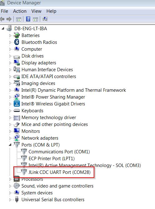
Figure 12 Device Manager Port
6.3. Configuring the Serial Port for UART
Several development tools require UART to be routed to the FTDI serial port. Refer to Figure 37 in Appendix B for the Basic Development Kit board connection verification and on how to properly configure the specific port.
6.3.1. Using Serial Port
To make sure that the communication between the Basic Development Kit board and the Windows development host is properly established, it is necessary to verify the UART connection between the two nodes.
On the Windows host, Tera Term can be used to validate the connection to the Basic Development Kit by following these steps:
Connect the Basic Development Kit board to the PC via USB cable. The location of the board’s USB port is shown in Figure 6.
Use the Windows Device Manager to verify that the host discovered the COM28 serial port in this case. See Figure 12.
Open Tera Term from the Windows Start menu as shown in Figure 13.
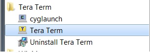
Figure 13 Start Tera Term
In the Tera Term: New connection dialog, select Serial, then select the COM Port to use, and click OK.
Select Setup > Serial Port and configure your UART port using the parameters shown in Table 1 (you need to be an administrator on your local machine), see Figure 14.
Settings |
Values |
|---|---|
Baud rate |
115200 |
Data bits |
8 |
Parity |
None |
Stop bits |
1 |
Flow Control |
None |

Figure 14 Setting Up the Port and Testing Connectivity via Tera Term
6.4. Troubleshooting
If there are any problems with the Basic Development Kit connection to PC some possible solutions might be:
Check for possible cabling issues by using a different USB cable.
Connect the two elements using a different USB port on the host PC.
Note
If none of these actions resolve the issue, please contact Dialog Tools Forums.