9. Your First DA1470x Application – FreeRTOS_Retarget
9.1. Introduction
The following sections explain how the user can build, program and run a simple software application called Freertos_retarget on the ProDK development board using the DA1470x SDK.
This application is basic for creating your own applications with FreeRTOS support.
It is a pre-defined project template called freertos_retarget
which is located at <sdk_root_directory>\projects\dk_apps\templates.
The application is first described, then step by step instructions are given to build and run it.
9.2. Software Architecture
In order to be familiar with building and executing the freertos_retarget project
is better to run it in (RAM) debug mode first. This is the easiest setup and does
not need any Flash programming prior to executing the binary.
When the application starts running the first thing that is executed is
the Reset_Handler, which is located in startup > DA1470x > GCC > exception_handlers.S.
This is followed by setting IRQ priorities and initializing variables.
Next, code execution continues with the main subroutine in file main.c.
Here, the main routine creates the task SysInit and starts the RTOS scheduler.
From now on the RTOS scheduler is running and it will start the first task which
is SysInit.
The SysInit first initializes the system clock and the low power clock and sets the
clock dividers for AHB and APB buses. Then the retarget function is initialized which leads to
initialization of the UART peripheral. This includes setting up the fifo mode,
dma, baudrate and enabling the communication power domain and the UART peripheral.
Main routine continues with wakeup configuration. It sets xtal as the clock that is used in wake up and wake up mode to normal wake up.
Last thing done before SysInit task exits is to create another task
prvTemplateTask which is the main application task running until the program gets
stopped. The function code implementing this main task is as follows:
static OS_TASK_FUNCTION(prvTemplateTask, pvParameters)
{
        OS_TICK_TIME xNextWakeTime;
        static uint32_t test_counter=0;

        /* Initialise xNextWakeTime - this only needs to be done once. */
        xNextWakeTime = OS_GET_TICK_COUNT();

        for ( ;; ) {
                /* Place this task in the blocked state until it is time to run again.
                   The block time is specified in ticks, the constant used converts ticks
                   to ms.  While in the Blocked state this task will not consume any CPU
                   time. */
                xNextWakeTime += mainCOUNTER_FREQUENCY_MS;
                OS_DELAY_UNTIL(xNextWakeTime);
                test_counter++;

                if (test_counter % (1000 / OS_TICKS_2_MS(mainCOUNTER_FREQUENCY_MS)) == 0) {
                        printf("#");
                        fflush(stdout);
                }
        }
}
The software as provided in the SmartSnippets™ DA1470x SDK – once up and running - interacts with a host PC and sends the character ‘#’ via the serial UART interface every 1sec. This can be verified by setting up a terminal application (see Section 6.3.3 for the procedure).
9.3. Software Build
This section describes all the steps required to import, build and run this first project.
In the SmartSnippets™ Studio welcome page click on the browse icon in the SOFTWARE RESOURCES tab [1] as shown in Figure 38.
Import the template project
freertos_retargetfrom:<sdk_root_directory>\projects\dk_apps\templates\freertos_retarget[2] into the selected workspace.
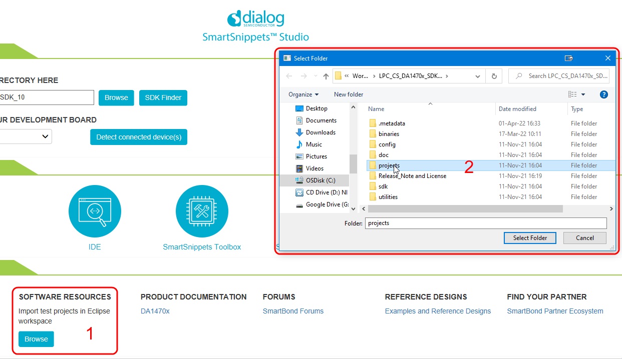
Figure 38 Project import
Import the
python scriptsby clickingfile > Import > Existing Projects into Workspaceand select thepython scriptsin theutilities.
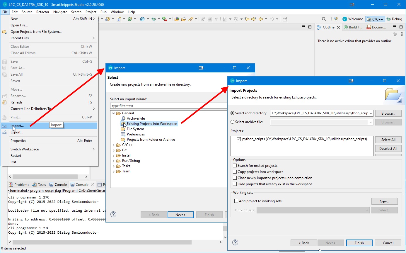
Figure 39 Load Python Scripts
9.3.1. Build the project to run from RAM
The first build to try is a RAM build. This is the simplest one as there is no need to write the code to external QSPI Flash, the debugger will load it directly into RAM from where it can be run. This is not the normal method of development.
Build the project with the Build button and select Debug RAM configuration DA1470x-00-Debug_RAM
as shown in Figure 40.
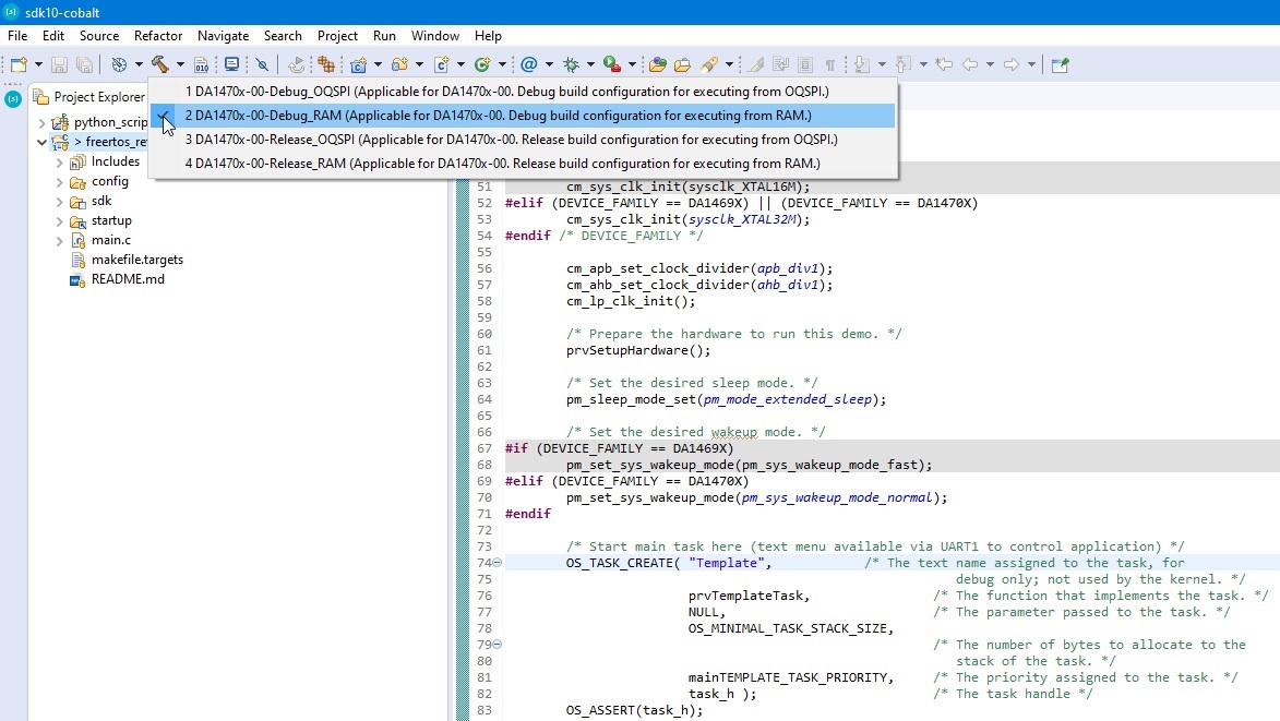
Figure 40 Build FreeRTOS Retarget in Debug RAM configuration
Once the Debug RAM binary is built, the next step is to start the Debugger using Run > Debug Configurations as shown in Figure 41. As this is a RAM build, the debugger will download the binary file via J-Link debugger into the system RAM. To enable this the system RAM is mapped to address 0 by the debugger.
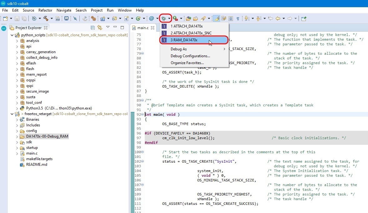
Figure 41 Start Debug in RAM mode
A new window will pop-up asking to select the correct jlink debugger:
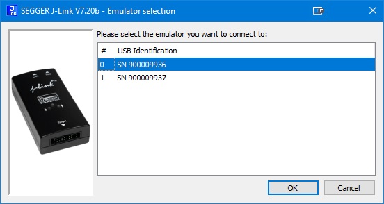
Figure 42 Jlink serial (number) select
Choose the lowest number and hit OK.
After the RAM image is loaded in the DA14706 through the debugger, the correct functionality can be checked by pressing the Resume button in the Eclipse Debugger window (see Figure 43). Open a serial terminal (115200, 8N1) and check if a # is printed every second.
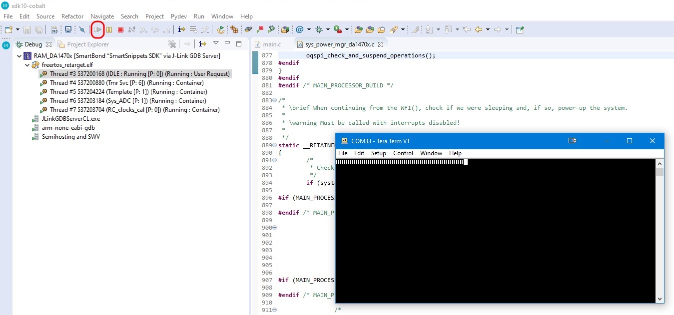
Figure 43 RAM Debug Window
9.3.2. Build the project to run from QSPI Flash
This will be the normal development flow which has three steps: build the code, write it to QSPI Flash and then run it in the debugger.
Build the project pressing the build button and select the Debug OQSPI configuration
DA1470-00-Debug_OQSPIas shown in Figure 44.
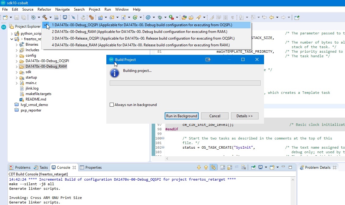
Figure 44 Build FreeRTOS Retarget in Debug OQSPI configuration
In order to write an image to Flash a configuration must be done first. Press Run->External Tools->program_oqspi_config to access the configuration menu (see Figure 45).
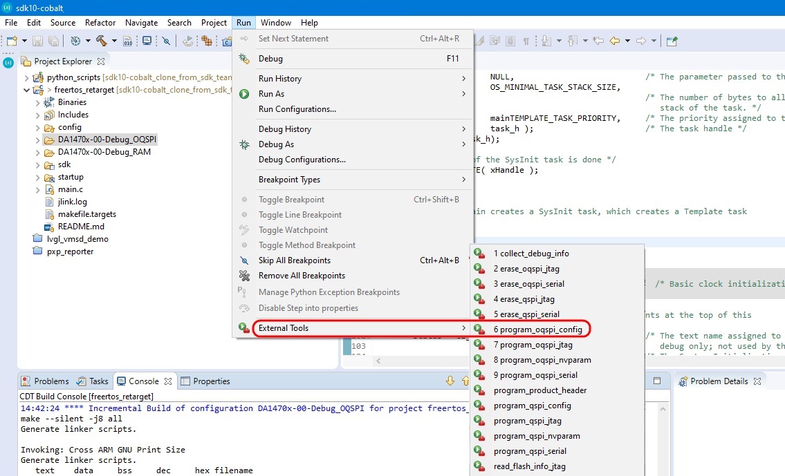
Figure 45 Flash Configuration Tool
This will open the window (Figure 46) with a summary of the current OQSPI configuration and supported device.
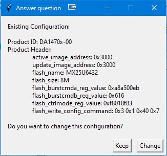
Figure 46 Configuration Tool
Click on the Change button, this will open a new window where one can select the product ID. (At this moment only DA1470x-00 is shown). Click OK and you will see a selection of various flash devices.
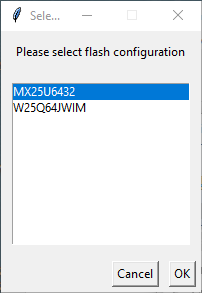
Figure 47 Flash Devices
For the Development Kit choose the first item: MX25U6432 and press OK. Press OK in the following two windows to choose the default value of 0x3000.
The next step is to write the binary file to (O)QSPI Flash. This is done by using a script selected from the
External Tool button. In Figure 48 select program_oqspi_jtag to program the
(O)QSPI Flash memory. (The external tools may not be populated at first use. To populate the External Tool button, press the
External Tools Configuration… button to manually add the menu items.)
Note
This action will erase the current program in the flash.
Alternatively, use Run > External Tools > program_oqspi_jtag.
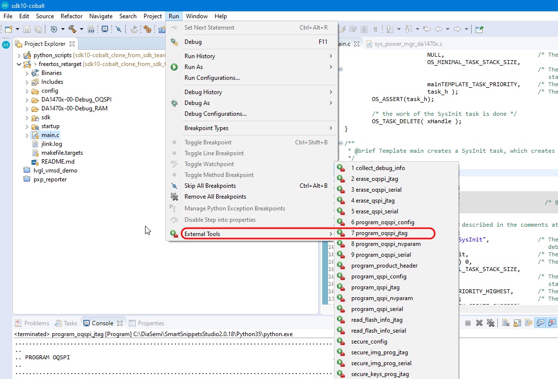
Figure 48 Write FreeRTOS Retarget to (O)QSPI Flash
Note: In some cases a new windows will pop up asking to select the correct jlink serial (number):
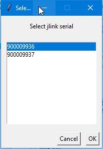
Figure 49 Select Jlink serial (number)
Choose the lowest number (in the above case : 900009936) and hit OK.
Note
The jlink serial number(s) can be found on the back of the motherboard.
Finally start the debugger using Run >Debug (F11) or click ‘Debug’ as shown in Figure 50. This will start the debug perspective in SmartSnippets™ and load the symbols for the current project into the debugger.
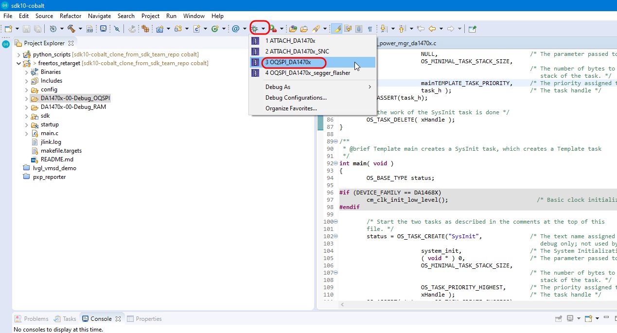
Figure 50 Start Debug in (O)QSPI mode
Note: A new window my pop up asking to select the correct jlink serial:
Figure 51 Jlink serial (number) select
Choose the lowest number and hit OK.
The debug session will start and execution will ‘pause’ at main. Hit F8 to resume.