10. Advertising Demo
10.1. Introduction
The following sections explain how the user can build, program and run a
simple software application called Advertising Demo ble_adv on the ProDK
development board using the SmartSnippets™ DA1470x SDK.
The application is first described, then step by step instructions are given to build and run it.
10.2. Software Architecture
In order to get familiar with building and executing ble_adv project, it
is better to run it in debug mode first. This is the easiest setup and does
not need any Flash programming prior to executing the binary.
When the application starts running the first thing that is executed is
the Reset_Handler, which is located in startup > DA1470x > GCC > exception_handler.S.
This is followed by setting IRQ priorities and initializing variables.
Next, code execution continues with the main subroutine in file main.c.
Here, the main routine creates the task SysInit and starts the RTOS scheduler.
From now on the RTOS scheduler is running and it will start the first task which
is SysInit.
The SysInit first initializes the clock and the low power clock and sets the
clock dividers for AHB and APB buses. Then BLE Adv is initialized which leads to
function initialization of BLE manager.
Last thing done before SysInit task exits is to create another task
ble_adv_demo_task which is the main application task running until the program gets
stopped. The function code implementing this main task is as follows:
static OS_TASK_FUNCTION(ble_adv_demo_task, pvParameters)
{
     int8_t wdog_id;

     /* Just remove compiler warnings about the unused parameter */
     ( void ) pvParameters;

     /* Register ble_adv_demo_task to be monitored by watchdog */
     wdog_id = sys_watchdog_register(false);

     /* Start BLE device as a peripheral */
     ble_peripheral_start();

     /* Set device name */
     ble_gap_device_name_set("Dialog ADV Demo", ATT_PERM_READ);

     /* Set advertising data */
     ble_gap_adv_data_set(sizeof(adv_data), adv_data, 0, NULL);

     /* Start advertising */
     ble_gap_adv_start(GAP_CONN_MODE_UNDIRECTED);

     for (;;) {
             ble_evt_hdr_t *hdr;

             /* Notify watchdog on each loop */
             sys_watchdog_notify(wdog_id);

             /* Suspend watchdog while blocking on ble_get_event() */
             sys_watchdog_suspend(wdog_id);

             /*
              * Wait for a BLE event - this task will block
              * indefinitely until something is received.
              */
             hdr = ble_get_event(true);

             /* Resume watchdog */
             sys_watchdog_notify_and_resume(wdog_id);

             if (!hdr) {
                     continue;
             }

             switch (hdr->evt_code) {
             case BLE_EVT_GAP_CONNECTED:
                     handle_evt_gap_connected((ble_evt_gap_connected_t *) hdr);
                     break;
             case BLE_EVT_GAP_DISCONNECTED:
                     handle_evt_gap_disconnected((ble_evt_gap_disconnected_t *) hdr);
                     break;
             case BLE_EVT_GAP_PAIR_REQ:
                     handle_evt_gap_pair_req((ble_evt_gap_pair_req_t *) hdr);
                     break;
             default:
                     ble_handle_event_default(hdr);
                     break;
             }

             /* Free event buffer (it's not needed anymore) */
             OS_FREE(hdr);
     }
}
10.3. Software Build
This section describes all the steps required to import, build and run this first project.
In the SmartSnippets™ Studio welcome page click on the IDE icon from the Tools tab as shown in Figure 52.

Figure 52 SmartSnippets™ Studio welcome page
Import the template project
ble_advfrom:<sdk_root_directory>/projects/dk_apps/demos/ble_advinto the selected workspace. Press the browse button highlighted in the Resources tab (reference 1) and navigate to the folder which contains the specific project as shown in Figure 53.
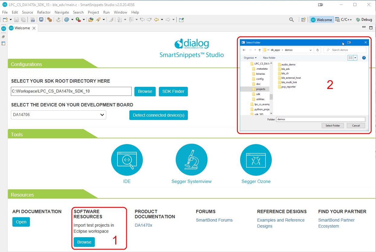
Figure 53 Project import
In the same way import the
python_scriptsproject from:<sdk_root_directory>\utilities\python_scripts
10.3.1. Build the project to run from RAM
The first build to try is a RAM build. This is the simplest one as there is no need to write the code to external O/QSPI Flash, the debugger will load it directly into RAM from where it can be run. This is not the normal method of development.
Build the project with the Build button and select Debug RAM configuration DA1470x-00-Debug-RAM
as shown in Figure 54.
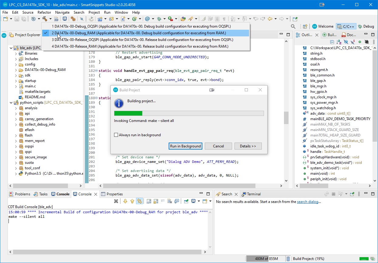
Figure 54 Build ADV BLE in Debug RAM configuration
Once the Debug RAM binary is built, the next step is to start the Debugger as shown in Figure 55. As this is a RAM build, the debugger will download the binary file via J-Link debugger into the system RAM. To enable this the system RAM is mapped to address 0 by the debugger.
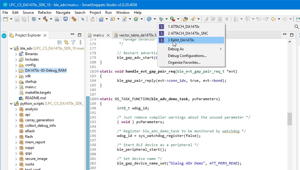
Figure 55 Start Debug in RAM mode
10.3.2. Build the project to run from O/QSPI Flash
This will be the normal development flow which has three steps: build the code, write it to QSPI Flash and then run it in the debugger. Some questions may pop-up about which Flash device etc, as explained later in the next section: Configure SmartSnippets™ to write to Flash
Build the project pressing the build button and select the Debug OQSPI configuration
DA1470x-00-Debug-OQSPIas shown in Figure 56.
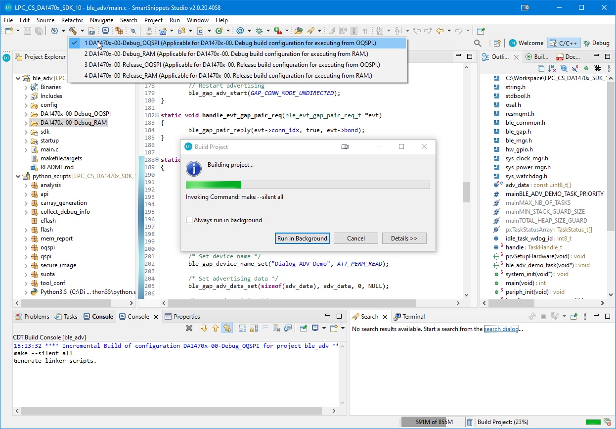
Figure 56 Build ADV BLE in Debug OQSPI configuration
The next step is to write the binary file to O/QSPI Flash. This is done by using a script selected from the
External Tool button. In Figure 57 select program_qspi_jtag to program the
QSPI Flash memory. (The external tools may not be populated at first use. To populate the External Tool button, press the
External Tools Configuration… button to manually add the menu items.)
Alternatively, use Run > External Tools > program_qspi_jtag.
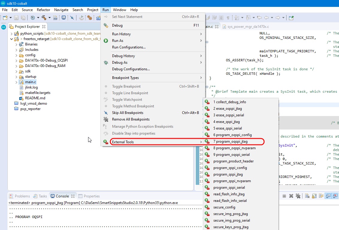
Figure 57 Write ADV BLE to O/QSPI Flash
Finally start the debugger as shown in Figure 58. This will start the debug perspective in SmartSnippets™ and load the symbols for the current project into the debugger.
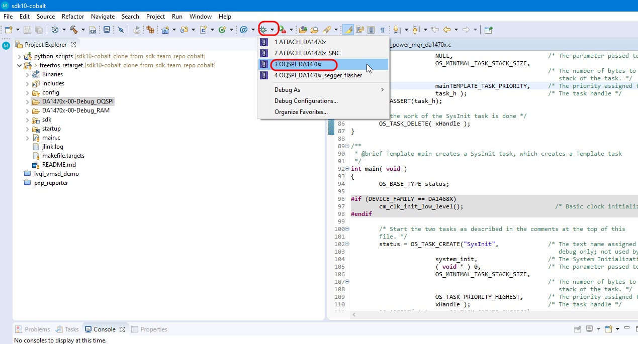
Figure 58 Start Debug in O/QSPI mode
10.4. Configure SmartSnippets™ to write to Flash
In order to write your application to another Flash version, a configuration must be done first. To access the configuration menu
alternatively, use Run > External Tools > program_oqspi_config program_oqspi_config, refer to Figure 57.
This will open the window as shown in Figure 59 with a summary of the current O/QSPI configuration and supported device.
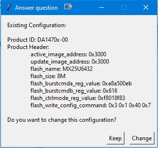
Figure 59 Configuration Summary
Press change to apply a new configuration. The first question has to do with the Product Id
Select DA1470x-00 product family.
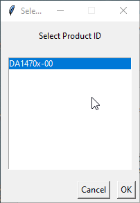
Figure 60 Select Product ID
Next you will be asked about the Flash configuration. For ProDK of the DA1470x family select MX25U6432.
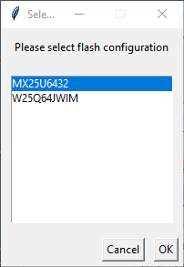
Figure 61 Select Flash configuration
Finally you will be asked to insert an address: Insert Active FW image address (hex) and Insert Update FW image address (hex).
Please keep in both entries the default value 0x3000.
Warning
Once your project is loaded and it is not working, it could that a wrong flash version was chosen. make sure to select the right flash version refer to Figure 61.
10.5. Running the project in the Debugger
Now that the binary has been loaded to memory (either RAM by debugger or O/QSPI by script) and the debugger has the symbols for the project loaded it is possible to run project in the debugger.
Start execution of the ADV BLE project by selecting Resume inside the SmartSnippets™ Run menu or by hitting the play icon as indicated in Figure 62.
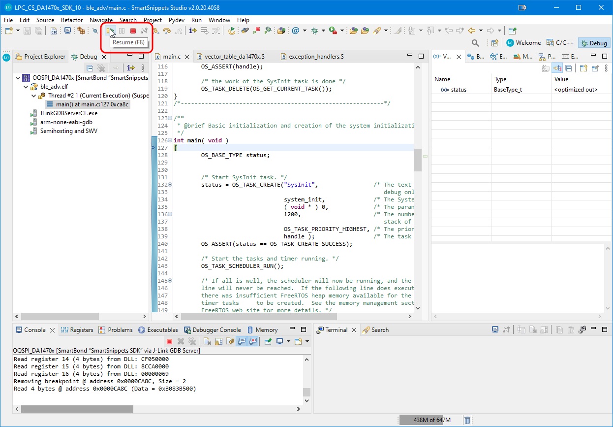
Figure 62 Executing the ADV BLE project in SmartSnippets™
The correct functionality of the ADV BLE project can be checked by noticing in the SmartBond BLE scanner application which can be installed from the Google Play website.
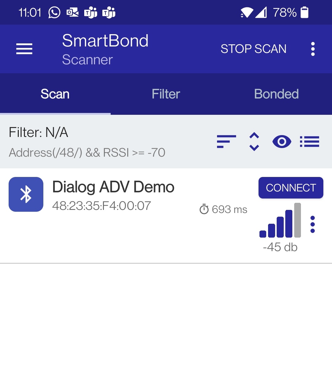
Figure 63 ADV BLE: Interacting with BLE Application
10.6. What Next ?
This tutorial does not cover all the topics relevant to the software development environment. It describes the first steps necessary to get started with the Pro Development Kit. For further reading the following links provide more information on DA1470x:
DA1470x Datasheet : To know more about the SmartBond™ DA1470x SoC.
DA1470x Resources : To get more info about available collateral.