1. Secure Boot
This tutorial aims to provide an in-depth analysis of the secure boot feature on the DA1469x Bluetooth SoC. The boot loader of the DA1469x, the DA1459x and DA1470x, supports secure boot and so, there is no need for invoking a secondary boot loader. On top of that, the embedded OTP memory contains a special area where secure keys are stored and can be securely locked to prevent reading and (over)writing. Three groups of product keys are supported, each consisting of up to 8 different keys. The size of each key is 256-bits in length. Following is a brief description of the aforementioned three groups of product keys:
QSPI FW Decryption Keys Area (Payload): This memory area holds symmetric keys utilized by the secure-QSPI controller for on-the-fly decrypting of the firmware image during execution.
Note
When the device operates in secure mode it is mandatory for the application image to be encrypted before storing it in to the FLASH device. Otherwise the device cannot boot. The same product key is used both for encrypting and decrypting the FW image.
Signature Keys Area (Payload): This memory area accommodates the public asymmetric keys. The public key is invoked by the BootROM code to authenticate and verify the validity of the signed firmware image. The private key of the asymmetric key pair is used for generating a digital signature of the target firmware image.
Note
The private keys are not stored on the device but need to be stored in a safe and secured place. These private keys are needed when an updated signed firmware image has to be created.
User Data Encryption Keys Area (Payload): This memory area holds symmetric keys used by the general-purpose AES crypto engine to encrypt/decrypt user-defined data. By using different symmetric keys for encrypting/decrypting user-defined data and the FW image, the secure mechanism is considered more robust.

Figure 1 Product Keys - OTP Area
For each product key there is a product key index, 4-bytes each, that designates the validity of that specific secure key. By default, the value of all key indexes is 0xFFFFFFFF. In fact, this is the value of an unwritten OTP memory cell. A key index value set to 0xFFFFFFFF designates a valid product key whereas, a key index value set to 0x00000000 designates a revoked and hence an invalid product key.
Note
The initial value of an OTP memory cell, integrated on the DA1469x, is logic 1. This value can be changed to logic 0. The opposite direction is not possible.
Symmetric key per device
To increase security even further, it is possible to create one symmetric key specific to each device and store it (in OTP slot 8) in the User Data Encryption Key Area. This key can be used to encrypt and decrypt local stored application data and (locally stored) bonding data.
1.1. Working with the Secure Boot Feature
This section describes the steps required to enable secure booting on the DA1469x SOCs. The steps are provided in the order they should be executed.
1.1.1. Step #1 - Importing Python Scripts
All functionality related to the secure boot feature can be found in the python_scripts project. This project contains several scripts which can be executed either directly via a terminal or from e2 studio. In this tutorial the latter option is demonstrated.
Note
This step is not required if scripts are executed externally via a terminal/command line. To avoid any misconfigurations it is highly recommended to work with the internal tools as provided in e2 studio.
On the e2 studio start page, ckick File and Import:

Figure 2 Open Project Browser
In the pop-up window, Select Dialog SDK Project and click Next:

Figure 3 Select Dialog SDK Projects
In the next pop-up window Browse towards the DA1469x SDK directory and when the Projects are populated, select the python_scripts and click Finish:
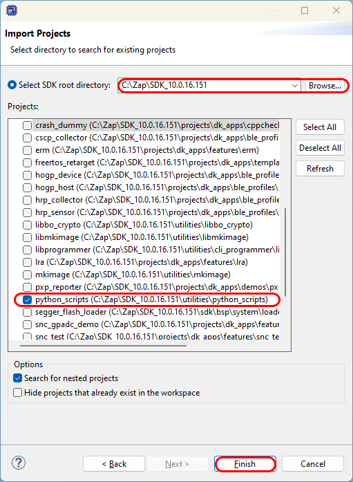
Figure 4 Select SDK Folder
Once the project is imported switch to C/C++ window. You should get the following output:

Figure 5 Select Target Project
1.1.2. Step #2 - Generating the Keys and the Secure Boot Configuration XML Files
The next step involves generating the product keys for all three keys categories. To do so, execute the following steps:
Run the
secure_configexternal tool from e2 studio.

Figure 6 Generating Product Keys - Running External Tool
In the console window you’ll be asked to create the product key file. Select Yes.

Figure 7 Generating Product Keys - Generating Product Keys
Next you’ll be asked to select the target family of devices. This should be the DA1496x-00. Select 1 (and press ‘Enter’)

Figure 8 Generating Product Keys - Selecting Target Family
After that you’ll be asked to skip (or not) the key generation for OTP slot 8, which is reserved for the Device Unique Symmetric Key (DUSK). Select (Y)es (for increased security) or (N)o.

Figure 9 Generating Product Keys - Selecting DUSK
Both types of symmetric keys and asymmetric keys are generated and written in file product_keys.xml
Next, you will be prompted to select if the secure boot feature should be enabled or not. To continue select (Y)es.

Figure 10 Generating Product Keys - Enabling Secure Boot
The next question you’ll be asked is to select which of the 8 public keys, written in
product_keys.xml, should be used for validating the signed FW image. The selected Public Key is used by the ROM booter to authenticate the FW image during boot. The corresponding Private Key is used for generating the digital signature of the application image. For demonstration purposes select the key index with index 1.

Figure 11 Generating Product Keys - Selecting Public Key Index
Note
Scripts do not check if the selected key is revoked, that is, if the key has been invalidated and is no longer valid.
Choose which of the 8 FW decryption keys, written in
product_keys.xml, should be used for decrypting the FW image. The selected key is used at run-time by the secure-QSPI controller to decrypt on-the-fly the FW image. It is imperative for the FW image to be encrypted using the same symmetric key. For demonstration purposes select the key with index 2.

Figure 12 Generating Product Keys - Selecting FW Decryption Key Index
Note
Scripts do not check if the selected key is revoked, that is if the key has been invalidated and is no longer valid.
The last step requires to select one or more keys that should be revoked. To continue, select No as revocation process is demonstrated at a later section in this tutorial.

Figure 13 Generating Product Keys - Revoking Keys
Upon successful keys generation, right-click on the python_scripts project and select Refresh to refresh its contents.
A new file, named product_keys.xml should be generated.
This XML file contains the 7/8 arbitrary keys for all three product keys categories.
The generated keys should also be displayed on the Console window at the bottom side of the IDE.

Figure 14 Product Keys XML File
Also a second file, named secure_cfg.xml, should also be generated in the script’s location. This file is used:
For encrypting and signing the target FW image
For writing the secure related entries in the Header Image section of the FW image
For enabling the secure boot feature by writing the appropriate entry in the
Configuration Scriptsection in OTP. This step is done only once. Following attempts to execute that step are ignored.

Figure 15 Keys Configuration XML File
Note
User is free to change secure_cfg.xml according to their needs without, though, changing the format of the underlying XML file.
1.1.3. Step #3 - Creating the secure image
If not done so, import your project into the workspace and compile a SUOTA (Software Update Over The Air) supported image:
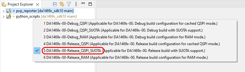
Figure 16 Create SUOTA image
Remark
In the SDK, only the Proximity Reporter Application has full SUOTA and security support.
Note
After programming the security flags in the OTP, the only way to update the application software is over the air, using SUOTA.
When the build is successful, both a secure- and non-secure image are created. Beside the product_keys.xml and the secure_cfg.xml file, a 3rd file is generated: nonce_cfg.xml.
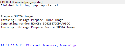
Figure 17 Image creation
1.1.4. Step #4 - Writing the Secure FW image in the FLASH
Next step is to write the secure FW image in the FLASH. It is important to have a valid secure FW image in the flash before enabling the secure boot feature.
Warning
If the secure boot feature is enabled either without valid secure FW image or without the correct keys programmed in the OTP, the device will be locked and there is no way to bypass this and program the device again.
To program the secured image and valid header in the qspi flash, go to the (external) tools and choose either secure_img_prog_jtag or secure_img_prog_serial:

Figure 18 Writing secure FW to FLASH
The secure_img_prog_jtag and secure_img_prog_serial scripts will encrypt the FW image using the key selected during the keys creation phase. It will create the FW image header with the security segments, generate the digital signature of the FW image (including the signed part of the FW image header) and add it to the FW image to be written in the FLASH.
Warning
Make sure that there is a valid secure FW image in the FLASH and the correct valid keys in the OTP to have a functional device. In case where the keys are wrong, or the FW image is not properly created, or the secure boot feature is not enabled, the device will be permanently disabled because such action falls in the device attack category and will activate the secure boot device protection feature and will be locked permanently.
1.1.5. Step #5 - Programming Product Keys & Enabling Secure Boot
After finishing generating the appropriate XML files and writing the secure FW image in the flash, the next step is to burn the product keys in the embedded One-Time-Programmable memory (OTP) and enable the secure boot feature. To do that you should:
Run the
secure_keys_prog_jtag/serialexternal tool from e2 studio. You are free to run the script employing either the serial port or JTAG interface.

Figure 19 Writing Product Keys in OTP - Running External Tool
If the secure boot feature is enabled in secure_cfg.xml, the tool will attempt to write the appropriate entry in the CS section in OTP. The status of each step is
displayed on the Console window at the bottom side. Once the writing process is complete and there are no errors, you should get the following output:

Figure 20 Writing Product Keys in OTP - Report Status
Note
If the secure boot feature is already enabled in CS, no action will be performed.
In case the product keys are already written in OTP you should get the following output:

Figure 21 Writing Product Keys in OTP - Report Status
In case the product keys are already written in OTP but do not match with the ones in product_keys.xml you should get the following output:

Figure 22 Writing Product Keys in OTP - Report Status
In case the product keys written in product_keys.xml are invalid you should get the following output:

Figure 23 Writing Product Keys in OTP - Report Status
Warning
It is of paramount importance to highlight that product keys safe storage and manipulation is customer’s liability. If the keys are lost, there is no way to recover them from the device once the SWD port and Development Mode are disabled. If all keys of a group are revoked the device will be permanently disabled. Renesas Electronics is not liable in any way for problems caused by either poor management and unsafe handling of the keys or revocation of all keys in a keys group.
1.2. Enabling Secure Boot Manually
The secure boot feature can also be enabled manually without invoking the corresponding python scripts. Enabling the secure boot, involves writing the appropriate entry in CS section in OTP. This value is used by the booter to configure the SECURE_BOOT_REG[SECURE_BOOT] bit-field. This configuration should take place before the device starts executing the FW image. In doing so, the chip will operate in secure boot mode which mainly involves authenticating and then decrypting, on-the-fly, the flashed FW image.
There are two main options for writing a value in OTP. The first option employs the SmartSnippets Toolbox and the second option makes use of the CLI programmer tool. In this tutorial, the former option is demonstrated. To continue execute the following steps:
Open the SmartSnippets Toolbox.

Figure 24 Start SmartSnippets Toolbox
When the SmartSnippets Toolbox opens, execute the following steps:
Click the Board (1) tab
Choose Device (2)
Pick DA1469x-00 (3) from the list
Check either UART or JTAG or both (4)
Finally click the OTP (5) tab

Figure 25 Opening a Project in the SmartSnippets Toolbox
Click on the Connect button (6) at the bottom. Log messages should be displayed on the Log window.
Note
When using the UART interface, you might be requested to press the RESET button on your application.
In the OTP Sections select the Configuration Script tab and click on the Icon as illustrated below.

Figure 26 Enabling Secure Boot Manually - Opening Configuration Script
In the Manage Configuration Script window select Register Configuration (1) and then click Add (2):

Figure 27 Enabling Secure Boot Manually - Adding New Entry
In the pop-up window click Select (3). In the newly displayed window search for
SECURE_BOOT_REG(4). Once the register is found, click on it (5) and then select OK (6). Next, declare the register’s value as illustrated below (7) and finally click OK (8).

Figure 28 Enabling Secure Boot Manually - Declaring New Entry
In the Manage Configuration Script window select OK (9).
In the OTP Header[Device: DA1469x-00] window click Burn to write the newly defined entry in OTP.

Figure 29 Enabling Secure Boot Manually - Writing to the OTP #1
A pop-up windows appears with a warning that writing the OTP may harm your chip:
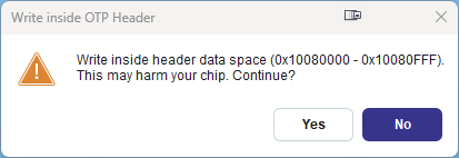
Figure 30 Enabling Secure Boot Manually - Writing to the OTP #2
In the pop-up window select Yes to write the previously defined entries in the OTP memory.
Warning
Once the secure boot feature is enabled, non-secure FW images cannot be started on the device. Moreover, disabling the secure boot mode is no longer possible.
1.3. Writing NONCE Parameter Manually
Users can also declare their own nonce value required by the AES crypto engine to decrypt the FW image. To do so, user can change the NONCE parameter directly in the nonce_cfg.xml file.
Note
Be aware that re-using the NONCE in consecutive software (update) images can have negative influence on the security and therefore it is recommended to us a different NONCE every time a new software image is created.
1.4. Revoking Product Keys
Key revocation is the process of invalidating one or more product keys written in OTP. The revocation procedure is performed by the ROM booter. The revocation information is delivered through the FW image header and thus, revoking one or more keys requires programming a new FW image in the FLASH device. The latter can be achieved either by overwriting the existing FW image stored in the FLASH device or adding a new image via the SUOTA functionality. Revoking a key involves destroying the key itself as well as invalidating the corresponding key index value in OTP. The latter is achieved by zeroing the key index value. The booter will ignore any revoked key(s) and will not use them to load the FW image. Any product key of all three categories can be revoked. Usually, the process of revoking one or more keys is imperative when a key has been leaked to the public.
Warning
At least, one FW decryption and one signature verification key should be valid in order for the device to boot. If all keys are revoked the device will not be able to boot.
The easiest way to proceed is to run the
secure_configexternal tool.

Figure 31 Revoking Product Keys - Running the External Tool
Note
Once product_keys.xml is generated, re-running secure_config will only modify secure_cfg.xml.
A window with the current keys configurations, read from
product_keys.xml, should be displayed. To continue click Change:

Figure 32 Revoking Product Keys - Changing the Keys Configuration File
In the Console window select the target family of devices. This should be the DA1469x-00.
In the displayed window select whether the secure boot feature should be enabled or not.
Next, you will be asked to select a valid public key index.

Figure 33 Revoking Product Keys - Revoking Public Keys
Select a valid FW decryption key index.
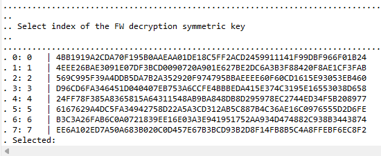
Figure 34 Revoking Product Keys - Enabling Revocation
Then you will be asked if key revocations should take place. Type Y(es).
Select which public key(s) should be revoked and finish with (capital) X.
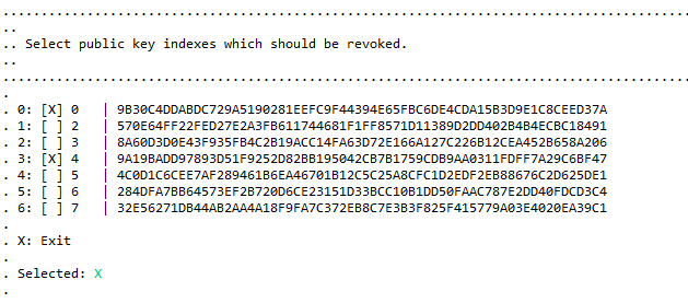
Figure 35 Revoking Product Keys - Public key Revocation
Next, you’ll be asked the same for the symmetric FW key(s) and the symmetric application key(s).
After you e(X)it, the configuration is saved to secure_cfg.xml
Note
Scripts do not check which keys are already revoked. If a key is revoked and its revocation is requested, no action is performed for the specified key.
If all above steps are executed successfully you should get the following output on the Console window:

Figure 36 Revoking Product Keys - Console Window
secure_cfg.xml should now be updated. Open the file and verify the updated Device Administration XML entries:

Figure 37 Revoking Product Keys - Updating the Keys Configuration File
Note
User can also change the Device Administration values directly in the file secure_cgf.xml by modifying the corresponding XML entries.
1.5. Known Restrictions and Limitation
The
secure_configexternal tool generates all 8 keys for all three keys categories. If fewer keys should be generated,product_keys.xmlshould be edited manually. Once the keys are written in OTP, the rest of the keys (not initially defined) cannot be written by re-runningsecure_keys_prog_jtag/serial. This operation should be done either via SmartSnippets Toolbox or the CLI programmer toolOnce the
product_keys.xmlfile is generated, it cannot be overwritten by re-runningsecure_config. If new keys have to be generated the keys file should be removed manually. In that case, do not forget to keep a copy of the keys fileScripts do not check which keys are already revoked; this information is printed only as log. If a key was revoked and its revocation is requested, then no action is performed for that specified product key
1.6. Troubleshooting
When the flashed application image cannot execute, check the following:
Possible Cause
Recommended Action
Secure boot is not enabled in the Configuration Script in OPT
Run
secure_configand enable the secure boot feature. Once the tool is executed successfully, runsecure_keys_prog_jtag/releaseto write the CS section in OTPThe signature verification and/or FW decryption keys, used by
secure_img_prog_jtag/serialto generate the FW image, do not match the keys stored in OTPMake sure that there is no other product keys file that might has been programmed to the OTP memory earlier
The currently selected signature verification and/or FW decryption keys have been revoked by the previous application image
At least one key in each category must be valid in order for the device to boot. Run
secure_configand select another valid key index. Then runsecure_img_pro_jtag/serialto sign and encrypt the application image with the selected keys
1.7. Further Increasing Device Security
The device can be further secured by permanently disabling its SWD port. In doing so, there is no longer the possibility for the chip to be accessed via the SWD/JTAG interface. The aforementioned state can be achieved by setting the
FORCE_DEBUGGER_OFFsticky bit ofSECURE_BOOT_REGto 0x01. To do so, the appropriate value should be written in the Configuration Script section in OTP. For more information on how to write a new Register Configuration entry in CS please refer to Enabling Secure Boot ManuallyAnother way to secure the device is to permanently disable the serial port so that no secondary bootloader can be utilized to load a new application image. This can be achieved by permanently disabling the
Development Modewhich, by default, is enabled at the initialization phase of the booter. More specific, the special value 0x70000000 will force the booter to disable theDevelopment Modeand run the device inProduction Mode. To do so, the aforementioned special value should be written in CS in OTP with the help of SmartSnippets Toolbox. For more information please read the Enabling Secure Boot Manually section. In this case the corresponding command type should be selected as illustrated below:

Figure 38 Disabling Development Mode
Note
In case a Register Configuration is declared multiple times in the Configuration Script section in OTP, the last pertinent entry will eventually determine the value of the target register.
Warning
Once the SWD port as well as Development Mode are disabled, a new application image can only be loaded through the SUOTA service, if enabled.