6. The DA14695MOD ProDK Hardware overview
6.1. Pin Definition
The figure below shows the pin assignment of the DA14695MOD. Table 1 in the DA14695MOD datasheet includes an overview of the pins description.
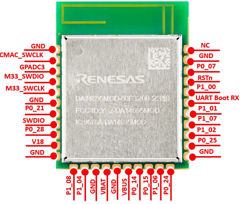
Figure 1 The DA14695MOD Pinout Diagram
6.2. The DA14695MOD daughterboard
Figure 2 and Figure 3 present the DA14695MOD Daughterboard.
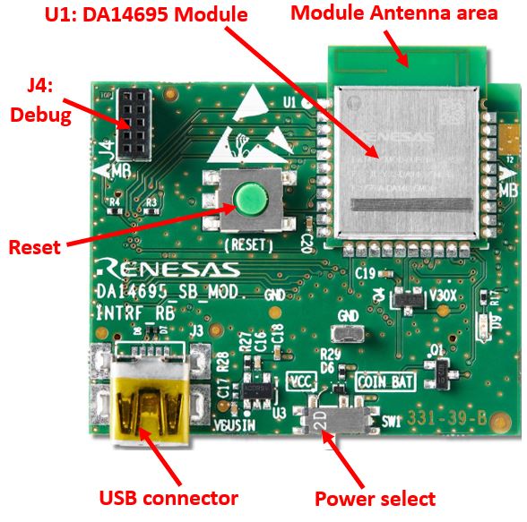
Figure 2 The DA14695MOD Daughterboard
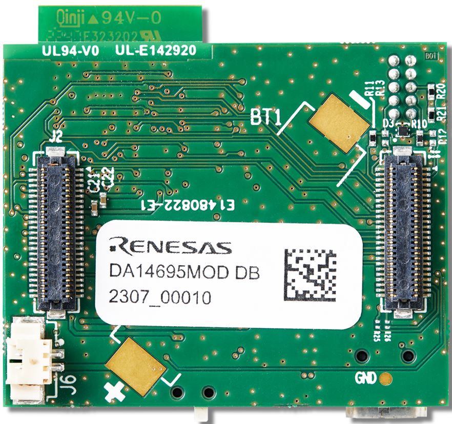
Figure 3 The DA14695MOD Daughterboard bottom
6.3. Connecting the DA14695MOD to DA14695 Mother Board
Figure 4 shows how the DA14695MOD is connected to the DA14695 mother board.
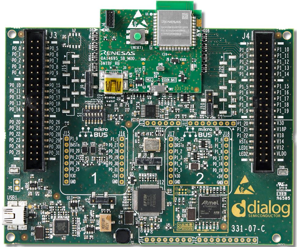
Figure 4 The DA14695MOD connected to the DA14695 mother Board
Note
The UM-B-093 DA1469x Devkit Pro Hardware User Manual shows How to Configure Power of DA14695 mother board.
The UM-B-090 DA1469x Getting Started with the Pro Development Kit shows how to setup the hardware development environment, install required software, download, and run an example application on the DA14695.