4. Additional Information
4.1. Memory Map
The memory map of an image that is using the SmartBoot bootloader is shown in the figure below.
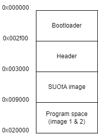
Figure 1 Memory Map
4.2. Image headers
If an image file needs to be added to the binary, an image (.img) with an image header needs to be generated. This can be achieved using SmartSnippets Toolbox and a version.h file. A guide on how to add this can be found here.
Note
In the guide, there is a mention of a version.h file. This version.h file can be created using any text editor and must contain the following version definition:
#define SDK_VERSION "1.0.0"
4.3. Execution of the SmartBoot bootloader when an application is loaded
When a valid application image has been loaded to flash along with the SmartBoot binary the application image will normally take precedence and it will be executed. To gain access again to the SUotA_only part of the SmartBoot binary and be able to upload a new image over SUotA there are two different ways, further analyzed below. Please note that the assumption is that a SmartBoot image along with a valid application image have been burned to flash and that the SUotA_only part is enabled along with the force SUotA GPIO configuration. If a valid application image is not found, SUotA_only will be always executing if it is enabled.
4.3.1. GPIO configuration
A feature where SUotA_only can be activated by setting a GPIO in a specific state during a power-cycle has been implemented. When the device boots, the secondary bootloader part of the SmartBoot will start executing. Amongst other things it will start sampling the force SUotA GPIO pin, according to the configuration that is programmed in the product header. If the pin is found in a different state than the preprogrammed default one, the secondary bootloader will load the SUotA_only application and execute it instead of the user application. By default, P0_11 pin is used as force SUotA pin in the input – pullup configuration. However, while creating the configuration using the webpage the user is free to select another configuration according to Table 1.
Values |
Comments |
|
|---|---|---|
GPIO Input type |
input, input – pull down, input – pull up |
Please note that if the input type is set to input the GPIO pin will be floating. An external mechanism - e.g., an active drive or a pull up/down resistor will have to be placed to ensure a valid logic level at the pin |
GPIO level |
active low, active high |
If the pin level is equal to the programmed active level the SUotA only application will be executed |
This option does not require any modification to the user application. In addition, this option can also be disabled through the webpage.
4.3.2. Magic word in flash
This option is more intrusive as it requires a small modification to the user application. However, it allows the user application to have full control over the time that the SUotA update will take place. A specific word is written at a specified memory location and then a software reset is performed. The secondary bootloader will check the memory location on boot and if the specific word is found the SUotA_only application will be loaded and executed. The following function or a similar one should be added within the user application and called when a SUotA update is to take place:
#define BOOTLOADER_MAGIC_WORD (0x4D4D4D4D)
#define MAGIC_WORD_MEMORY_LOCATION (0x07FCBFFC)
static void reboot_into_suota_only(void)
{
// Place a word in RAM to trigger s SUotA at reboot
uint32_t bootloader_magic_word = BOOTLOADER_COOKIE_WORD;
uint32_t magic_word_memory_location = MAGIC_WORD_MEMORY_LOCATION
memcpy((uint8_t *) magic_word_memory_location, &bootloader_magic_word,
sizeof(uint32_t) );
// Force a SW reset into ROM
uint16_t tmp = GetWord16(SYS_CTRL_REG);
tmp = (tmp & 0xFFFC)|0x00; // ROM remap address: 0x00
tmp |= SW_RESET;
SetWord16(SYS_CTRL_REG, tmp);
}
Whereas the magic word itself is not configurable unless the SmartBoot is recompiled, it is possible to change the address where the magic word is stored and checked upon boot. Care must be taken to ensure that the address is not overwrien by the secondary bootloader during the rebooting process. For that reason, it is recommended that this address is located towards the end of system RAM.
A dedicated characteristic can be added within the user application, so that the central device can control the SUotA_only execution. The concept can be expanded by adding security to the application so that only paired devices can initiate SUotA_only. The SUotA_only supports the usage of the pairing information provided by the application and therefore the new image can only be uploaded by the paired device. Please note that while the security mechanism exists, it is up to the user to implement the characteristic in the application.
4.4. Image upload feature description
In addition to transferring the user application image to flash wirelessly using SUotA, it is possible to use the tool to create a combined binary that apart from the SmartBoot binaries (secondary bootloader, SUotA only) also contains a valid user application image. The tool has a dedicated region in the expert mode of operation where an application image can be dropped. The application image must have a .img extension and contain a valid 64-byte single image header at the beginning of the file. It is practically the same file that would be used to perform a SUotA update. Any standard SUotA tool by Renesas can be used to create this file.
4.5. SmartBoot security features
The SmartBoot application itself does not support security in the sense that the user cannot enforce pairing when uploading a new image. However, the SmartBoot application can use existing pairing data that have been saved in a dedicated region by a valid user application that has been burned in flash previously or uploaded through SUotA. From a practical perspective that means that the SUotA_only part of SmartBoot will allow connections from previously paired devices, provided that pairing information is valid and available. In that case, SUotA_only will actively refuse connections from non – paired devices. The pairing information can only be set (and changed) by a valid user application. Therefore, the user application has the responsibility to add, modify or erase pairing data. If no pairing information is found or is invalid, the SUotA_only application will accept connections from any device.
4.6. Operation
The way the SmartBoot bootloader works to load the correct image and update images is explained in the flowchart below.
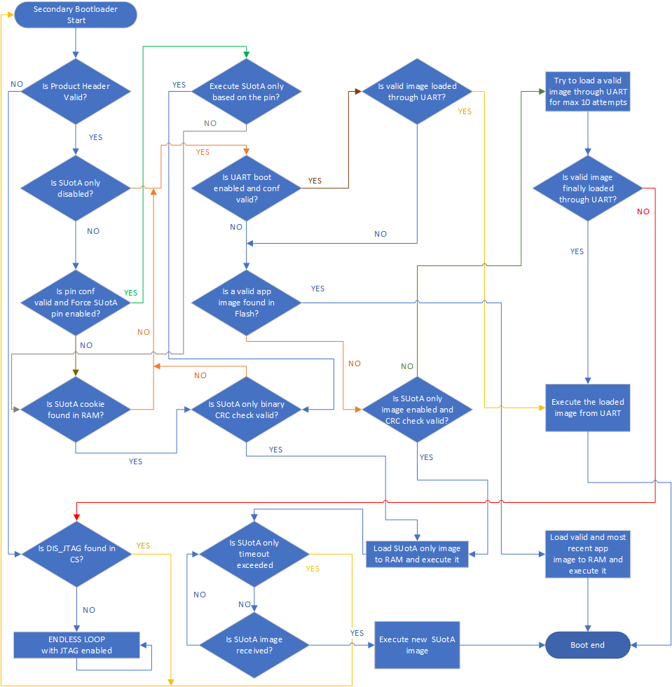
Figure 2 SUotA only flowchart
4.7. Header
The SmartBoot header controls setting of the SmartBoot bootloader and the SUotA image. The control fields and their addresses are listed in the table below.
Element |
Start Address |
Type |
Octets |
|---|---|---|---|
Product header identifier |
0x00002F00 |
uint16_t |
2 |
Product header version |
0x00002F02 |
uint16_t |
2 |
Firmware Img A offset |
0x00002F04 |
uint32_t |
4 |
Firmware Img B offset |
0x00002F08 |
uint32_t |
4 |
DSPS configuration offset 1 |
0x00002F0C |
uint32_t |
4 |
DSPS configuration offset 2 |
0x00002F10 |
uint32_t |
4 |
SUotA_only offset |
0x00002F14 |
uint32_t |
4 |
SUotA_only Img size |
0x00002F18 |
uint16_t |
2 |
SUotA_only Img CRC32 |
0x00002F1C |
uint32_t |
4 |
SUotA_only Advertising Data |
0x00002F20 |
32 |
32 |
SUotA_only Scan Response Data |
0x00002F40 |
32 |
32 |
SUotA_only BD Name |
0x00002F60 |
32 |
32 |
SUotA_only Advertising interval [ms] |
0x00002F80 |
uint16_t |
2 |
SUotA_only Timeout [s] |
0x00002F82 |
uint16_t |
2 |
UART timeout [ms] |
0x00002F84 |
uint16_t |
2 |
UART Baud rate |
0x00002F88 |
uint32_t |
4 |
UART TX Port |
0x00002F8C |
uint8_t |
1 |
UART TX Pin |
0x00002F8D |
uint8_t |
1 |
UART RX Port |
0x00002F8E |
uint8_t |
1 |
UART RX Pin |
0x00002F8F |
uint8_t |
1 |
Force SUotA_only Port |
0x00002F90 |
uint8_t |
1 |
Force SUotA_only Pin |
0x00002F91 |
uint8_t |
1 |
Force SUotA_only Input type |
0x00002F92 |
uint8_t |
1 |
Force SUotA_only Input level |
0x00002F93 |
uint8_t |
1 |
Flash Deep Sleep Command (DPD) |
0x00002F94 |
uint8_t |
1 |
Magic word memory location |
0x00002F98 |
uint32_t |
4 |
Security configuration address |
0x00002F9C |
uin32_t |
4 |
Bluetooth address |
0x00002FA0 |
uint8_t |
6 |
CRC32 (entire product header except self) |
0x00002FFC |
uint32_t |
4 |