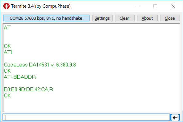
You can begin with first example wherein you send AT as a command on the terminal and you receive OK. This verifies that the connection is established.
AT” gives you the CodeLess version and type description
AT+BDADDR displays your BD Address as show in Figure 22
You can connect an analog voltage from an external source and do the experiment again. This way you can verify what voltage you are measuring as compared to the input supply.
Note
The ADC value will be around 930 for a 3V voltage on the ADC input. The max voltage that can be measured is 3.6V for 3x attenuation.
AT+IOCFG=11,7 (Pin P1_1 represented here as “11” is used as SCL, “7” is Hardware AT command for I2C CLK … refer AT Commands section )
AT+IOCFG=2,8 (Pin 0_2 , “8” is Hardware AT command for I2C SDA)
AT+I2CSCAN (This gives you the sensor slave address, seen here as 0x18)
AT+I2CCFG=7,400,16
(The slave addressing bit count: “7” for 7 bit or “10” for 10 bit;
The bit rate: “100” for 100 kbit/s or “400” for 400 kbit/s;
The slave register width: “8” for 8 bit or “16” for 16 bit.)
AT+I2CREAD=0x18,5
(read the sensor at hardware address 0x18, register 5)
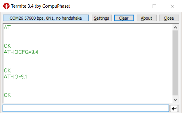
AT+IOCFG=9,7 (Pin P0_9 represented here as “9” is used as SCL, “7” is Hardware AT command for I2C CLK … refer AT Commands section)
AT+IOCFG=11,8 (Pin 0_11 , “8” is Hardware AT command for I2C SDA)
AT+I2CSCAN (This gives you the sensor slave address, seen here as 0x18)
AT+I2CCFG=7,400,16
(The slave addressing bit count: “7” for 7 bit or “10” for 10 bit;
The bit rate: “100” for 100 kbit/s or “400” for 400 kbit/s;
The slave register width: “8” for 8 bit or “16” for 16 bit)
AT+I2CREAD=0x18,5
(Read the sensor at hardware address 0x18, register 5)
Commands can be stored in the command slots and triggered either by a command or by a timer.
The following is a blinky example that toggles the board led of basic kit every 1 sec:
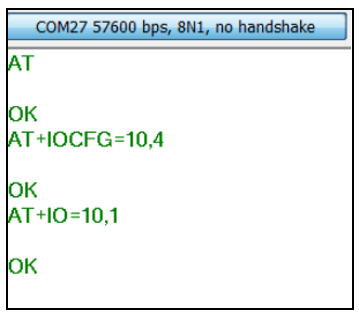
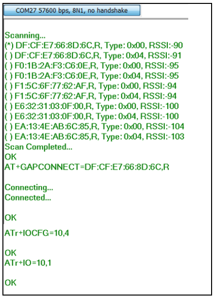
AT+IOCFG=10,4 (Set up pin 10 as GPIO output)
AT+CMDSTORE=0,AT+IO=10,1;AT+TMRSTART=0,1,100 (Command slot 0:Turn led on and after 1 sec run command slot 1)
AT+CMDSTORE=1,AT+IO=10,0;AT+TMRSTART=1,0,100 (Command slot 1:Turn led off and after 1 sec run command slot 0)
AT+CMDPLAY=0 (Trigger command sequence in command slot 0)
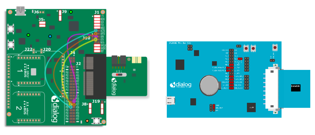
The general setup to perform remote AT commands is similar to the setup as shown in the above examples, except, we have another board with a similar configuration.
The board setup for the DA14585/586 and DA14531 is as shown below. Any combination is possible.
DA1453x and DA1458x (Remote)
DA1453x and DA1453x (Remote)
DA1458x and DA1453x (Remote)
DA1458x and DA1458x (Remote)
Setup:
Connect both the DA145xx Pro-DK and the DA14580 Pro-kit via USB to the PC.
As before, make a note of the COM ports from device manager.
Note the BD Address of both the boards.
Execute remote AT commands from the server or the client sides.
Note
Take a note of “r” in the AT commands. It indicates that you are referring to the remote board.
Figure 31 Remote Example Setup for the Combination DA1453x and DA1458x (Remote)