10. AT commands parameters
In the CodeLess Examples section of this manual, you are asked to refer to AT commands. Here is an example how the list can help to select the correct GPIO pins for the relevant examples.
- For example, to configure P1_1 as I2C Clk:
AT+IOCFG=11,7
where placeholder “11” = Port_1 Pin_1 (P1_1) and “7” is Hardware AT command for I2C Clk
Similarly, if you want to configure P0_2 as analog output, use the following command:
AT+IOCFG=2,6
In case the AT+IOCFG command is executed without arguments the current configuration of the pins will be printed back. The output depends on the version of the IC that is being used.
In case of the DA14531 FCGQFN24 version the AT+IOCFG command will print twelve bytes, implying 12 GPIOs available to use as in Figure 68.
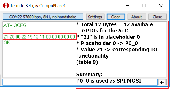
Figure 73 AT+IOCFG without Parameters
This gives an indication of number of pins available for SoC being used.
Placeholder |
Pin |
|---|---|
0 |
P0_0 |
1 |
P0_1 |
2 |
P0_2 |
3 |
P0_3 |
4 |
P0_4 |
5 |
P0_5 |
6 |
P0_6 |
7 |
P0_7 |
8 |
P0_8 |
9 |
P0_9 |
10 |
P1_0 |
In case of the DA14585/586, thirty-seven bytes will be printed back. The following table describes the association between the placeholders and the actual pins.
Placeholder |
Pin |
|---|---|
0 |
P0_0 |
1 |
P0_1 |
2 |
P0_2 |
3 |
P0_3 |
4 |
P0_4 |
5 |
P0_5 |
6 |
P0_6 |
7 |
P0_7 |
8-9 |
Not used |
10 |
P1_0 |
11 |
P1_1 |
12 |
P1_2 |
13 |
P1_3 |
14 |
P1_4 |
15 |
P1_5 |
16-19 |
Not used |
20 |
P2_0 |
21 |
P2_1 |
22 |
P2_2 |
23 |
P2_3 |
24 |
P2_4 |
25 |
P2_5 |
26 |
P2_6 |
27 |
P2_7 |
28 |
P2_8 |
29 |
P2_9 |
30 |
P3_0 |
31-36 |
Not used |
10.1. General-Purpose Input/Output Configuration
CodeLess provides mainly the AT+IOCFG command which can be used to configure the various pins of the device. The following IO functionality numbers are part of the AT+IOCFG configuration.
IO Functionality |
Function |
Comment |
|---|---|---|
0 |
Undefined |
Default at boot-up |
1 |
Input |
|
2 |
Input with pull-up |
|
3 |
Input with pull-down |
|
4 |
Output |
Push-Pull |
5 |
Analog Input |
Only port P0_0 to P0_3 |
6 |
Analog Input (attenuates input voltage 1:3) |
Only port P0_0 to P0_3 |
7 |
I2C CLK |
Only one pin can be defined. |
8 |
I2C SDA |
Only one pin can be defined. |
9 |
Connection indicator |
The pin is configured as output with a low default status which will change to high when a connection takes place. |
10 |
Connection indicator |
The pin is configured as output with a high default status which will change to low when a connection takes place. |
11 |
UART1 TX pin |
Pin is configured as UART1 data transmission pin. Only the application can configure this IO functionality. |
12 |
UART1 RX pin |
Pin is configured as UART1 data reception pin. Only the application can configure this IO functionality. |
13 |
UART1 CTS pin |
Pin is configured as UART1 CTS pin. Only the application can configure this IO functionality. |
14 |
UART1 RTS pin |
Pin is configured as UART1 RTS pin. Only the application can configure this IO functionality. |
19 |
SPI CLK |
Pin is configured as the SPI clock. Only one pin can have this functionality at a time. If flash memory is enabled this pin is handled by the application code. |
20 |
SPI CS |
Pin is configured as SPI chip select. Only one pin can have this functionality at a time. If flash memory is enabled this pin is handled by the application code. |
21 |
SPI MOSI |
Pin is configured as SPI master-output-slave-input. Only one pin can have this functionality at a time. If flash memory is enabled this pin is handled by the application code. |
22 |
SPI MISO |
Pin is configured as SPI master-input-slave-output. Only one pin can have this functionality at a time. If flash memory is enabled this pin is handled by the application code. |
24 |
PWM |
Pin is set as output, generating a PWM pulse according to the parameters specified by the AT+PWM command. |
27 |
Heartbeat |
Pin is set as output changing status approximately every second to indicate to an external host that the CodeLess software is running. |
28 |
Not available |
The pin is not available for use. |
10.2. CodeLess Error Codes
The following tables gives the list of CodeLess error code.
Error ID |
Error source |
|---|---|
0 |
|
1 |
|
2 |
|
3 |
|
4 |
|
5 |
|
6 |
|
7 |
|
8 |
|
9 |
|
10 |
|
11 |
|
12 |
|
13 |
|
14 |
|
15 |
|
16 |
|