4. Running The Demonstration Example
This section describes the steps required to prepare the Pro DevKit and other tools to successfully run an example. The example is based on the freertos_retarget
sample code found in the SDK, which prints the character # on a regular basis (once every second). To make things more interesting, let’s give some extra functionality
to the device making the Pro DevKit to toggle the red LED on the Pro Development Kit by a button press. Therefore a wake-up interrupt timer is added to handle this external event.
For demonstration purposes, the K1 button on the Pro Development Kit has been configured as a wake-up input pin.
(For more information on the wake-up controller, read the External Interruption Tutorial )
There are two main methods to verify the correct behavior of the demonstrated code. The first method is to use a Serial Terminal and the second is to use the SmartSnippets™ Toolbox.
4.1. Verifying with a Serial Terminal
Establish a connection between the target device and your PC through the USB1 port of the motherboard. This port is used both for powering and communicating to the DA1459x SoC. For this tutorial a Pro DevKit is used.
Import and then make a copy of the freertos_retarget sample code found in the SDK of the DA1459x family of devices.
Note
It is essential to import the folder named python_scripts to perform various operations (including building, debugging, and downloading)
In the target application, add/modify all the required code blocks as illustrated in the Code Overview section.
Build the project either in Debug_eFlash or Release_eFlash mode and burn the generated image to the chip.
Press the RESET button on Pro DevKit to start the chip executing its firmware.
Select your favorite serial console. In this tutorial we have selected Tera Term which is a free and easy-to-use serial terminal. Follow the steps below to successfully establish a connection via the USB port. If the target device is connected to your PC it should be automatically displayed as an option (2).
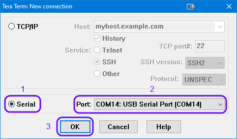
Figure 14 Select the Serial Port to which the Development Kit is Connected
Select the in the SetUp the serial port to set the UART parameters:
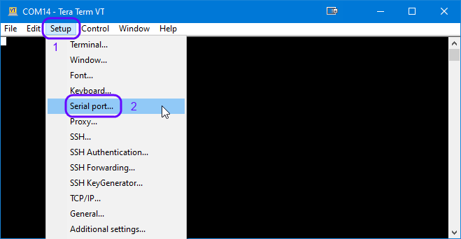
Figure 15 Select Serial parameter SetUp
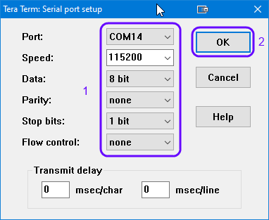
Figure 16 Configure the Serial Port with the correct settings
After successfully setting the serial port you should see the special character ‘#’ displayed on the console.

Special character ‘#’ is displayed in the terminal window
Press and release the K1 button on Pro DevKit. LED D1 on Pro DevKit should be turned on and off every second. For as long as LED D1 is active, the device is not allowed to enter sleep.
Press and release the K1 button on Pro DevKit again. LED D1 should be turned off and the device should enter sleep.
4.2. Verifying with SmartSnippets Toolbox
Another useful tool that can be used both for debugging and power measurements is the SmartSnippets™ Toolbox.
With the system up and running, open the SmartSnippets™ Toolbox and execute the following steps:
Select Project(1) and New(2) to create a new project. Give the new project a filename (ex: Starting_new_project).

Figure 17 Create New Project
Select Board(3), Device(4) and select the BLE device on your board (5)
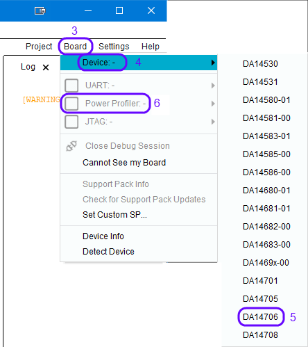
Figure 18 Select Device
Select the communication port for the Power Profiler(6) (Check the Device Manager for the last USB serial COM port).
Select Monitor(7) and the Power Profiler (8 & 9)
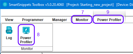
Figure 19 Select Power Profiler
Press the initialize button(10), press start(11) and press the RESET button on the Pro Development Kit.
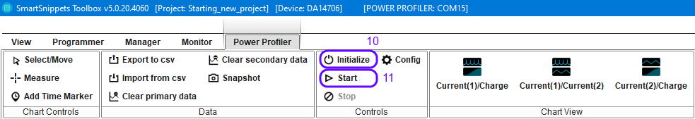
Figure 20 Start Power Profiler
Shortly after the Power-on-Reset (POR) the system will enter sleep mode and wake-up every second to print ‘#’ on the terminal.
Press and release the K1 button on the Pro Development Kit. Verify the increased power consumption when the device is in active mode and the Led is on.
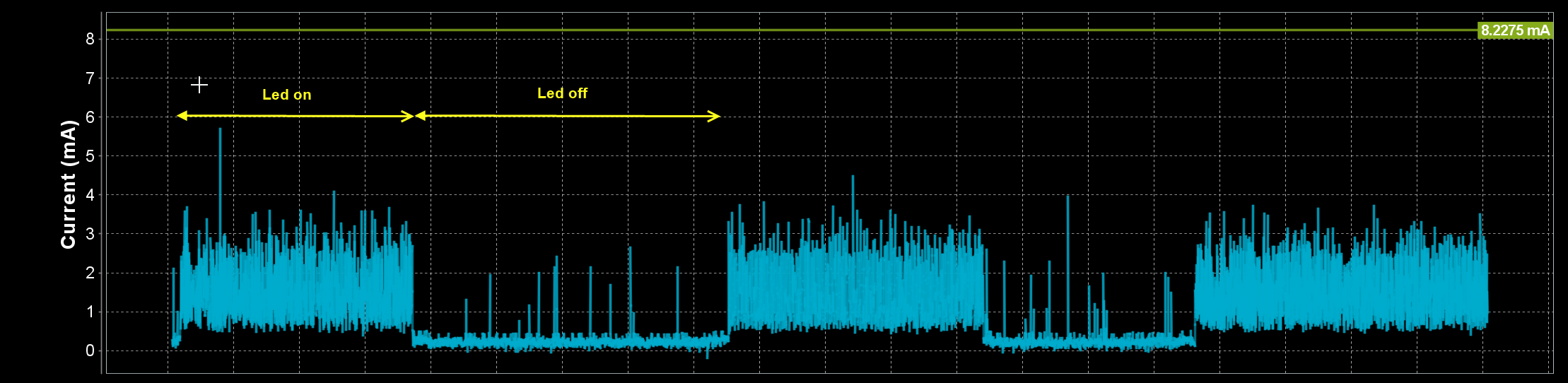
Figure 21 Verify difference in power consumption