4. Launch e2 studio and create the RL78 application
Important
Follow the links below to access and download the pre-configured software example:
4.1. create the Renesas RL78 C/C++ Project
If you have not done so already, download and install e2 studio. Additionally, if you have not yet installed the QE BLE Tool you can do that now by following these Instructions.
Launch e2 studio. e2 studio can be launched from the Windows start menu. If you have multiple versions of e2 studio installed, please make sure to launch the version of e2 studio that is specified in the prerequisites section. In the Eclipse Launcher window, specify the destination for the new workspace. It is recommended to keep the path simple and avoid using spaces.

Figure 8 Eclipse Launcher window
Click Launch to start e2 studio in the specified path. When prompted, log into your My Renesas account or click Cancel to dismiss the pop up window asking for permission to log and report usage (it will remain disabled). Select No when prompted for setting up a password hint.
The welcome screen may show inside the new workspace. It can be dismissed by clicking on the Hide button in the top-right corner.
Figure 9 Hide button in the top-right corner
Go to File -> New and select C/C++ Project.
In the new project wizard window, select Renesas CC-RL C/C++ Project and click Next
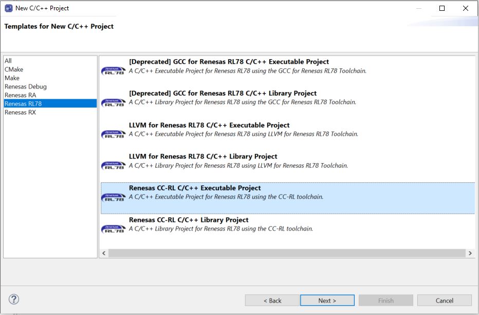
Figure 10 Renesas RA C/C++ Project
Specify a project name and Click Next.
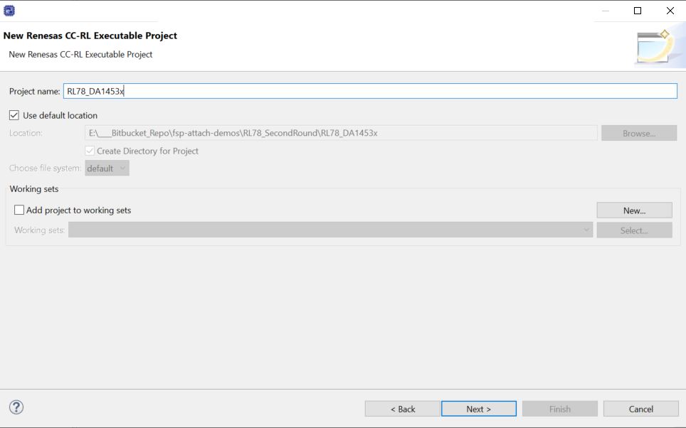
Figure 11 Project name
In the Device Settings, choose RL78G23-128p_FastPrototypingBoard for the Target Board. The correct device will be selected automatically based on the board that was chosen. Click Next.
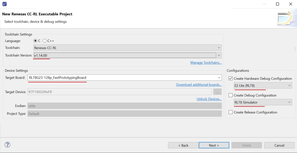
Figure 12 Device Settings
Important
If the device is not available, select Download additional boards… and download the Board description file for Fast Prototyping Board for RL78/G23-128p Board Description File
Check Use Smart Configurator and click the Finish button.
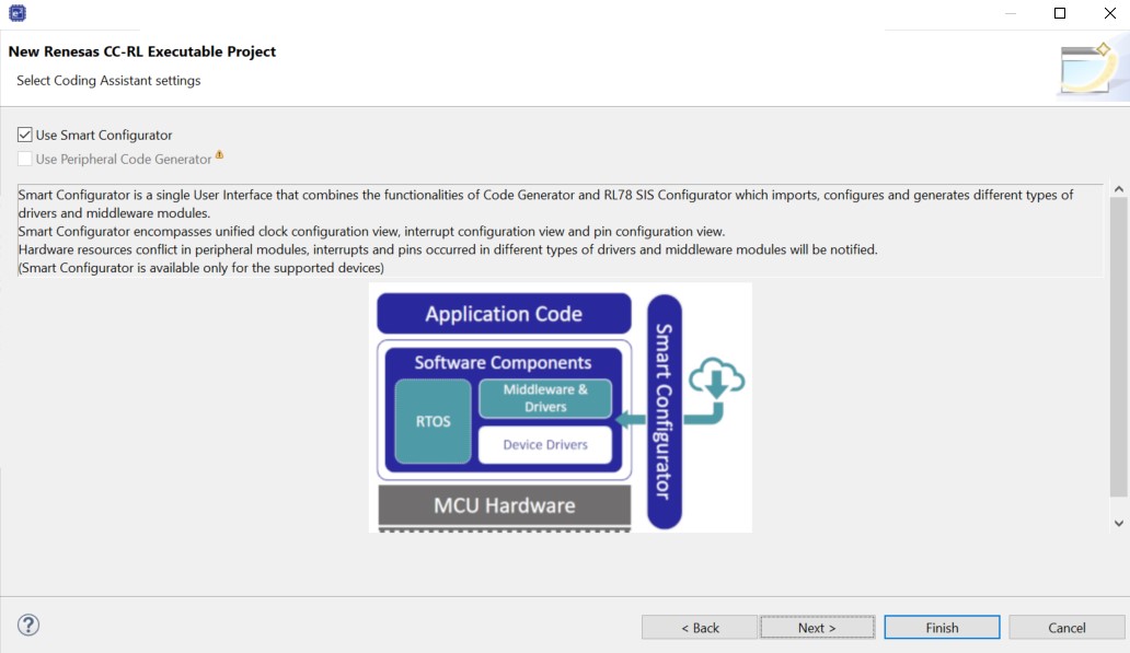
Figure 13 Finalizing the Project
In the next steps, the related module (BSP, UART, PORT) will be configured. Select r_bsp module and confirm that Initialization of peripheral function by Code Generator/Smart Configurator is set to Enable.
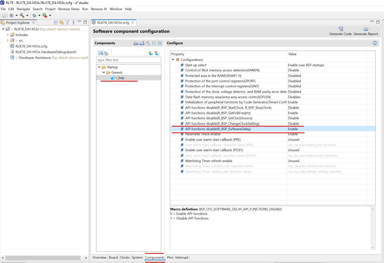
Figure 14 Setup of r_bsp
Setup of Serial Interface (UART). Select Components tab in the Smart Configurator.
Click Add Components button. In the displayed dialog, select UART Communication module and click Next button. Then set as follows and click Finish:
Operation: Transmission/reception
Resource: UART3
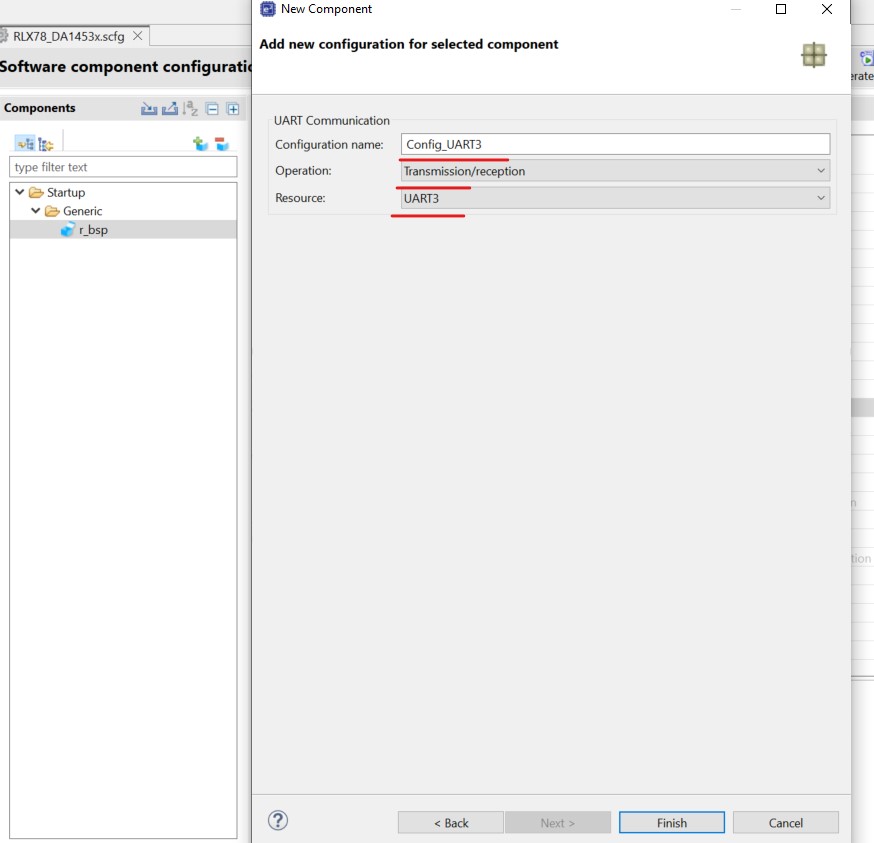
Figure 15 UART Communication Module
Click the added UART Communication module and set the operation clock and transfer rate (baud rate) in the Transmission and Reception sections
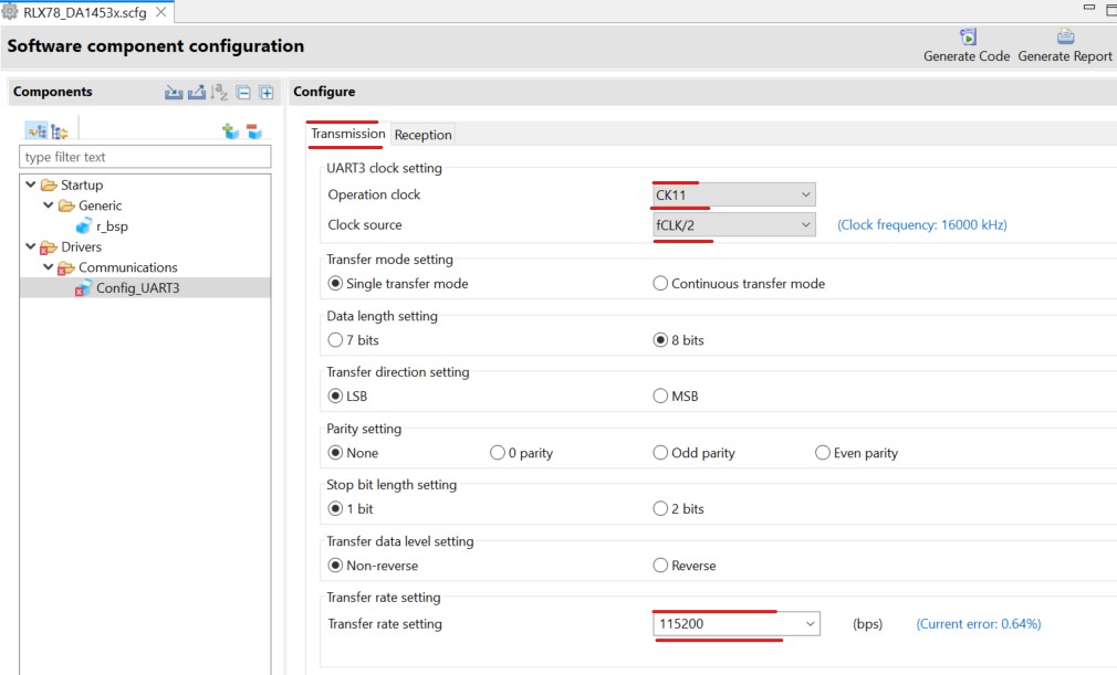
Figure 16 Setup Transmission of UART Communication Module (UART3)
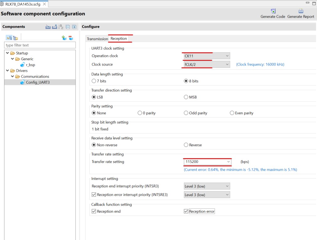
Figure 17 Setup Reception of UART Communication Module (UART3)
Setup PORT module. Click Add Components button. In the displayed dialog, select PORT
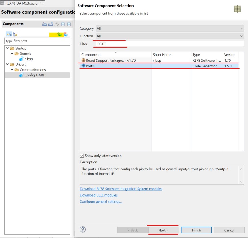
Figure 18 PORT Communication Module
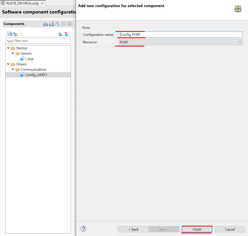
Figure 19 PORT Communication Module configuration
Select the following PORTs:
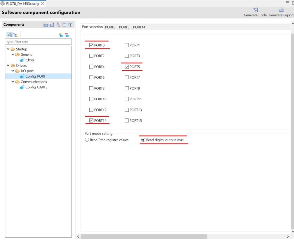
Figure 20 PORT Communication Module selection
Configure PORT0 as follow:
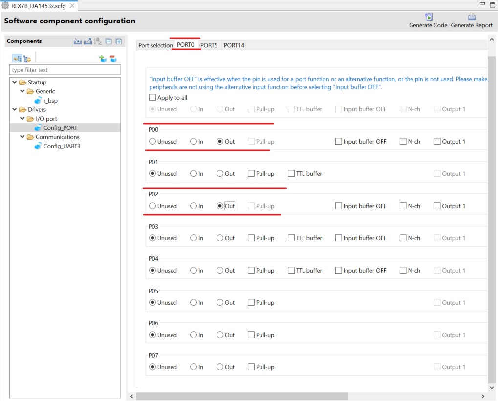
Figure 21 PORT0 Communication Module
Configure PORT5 as follow:
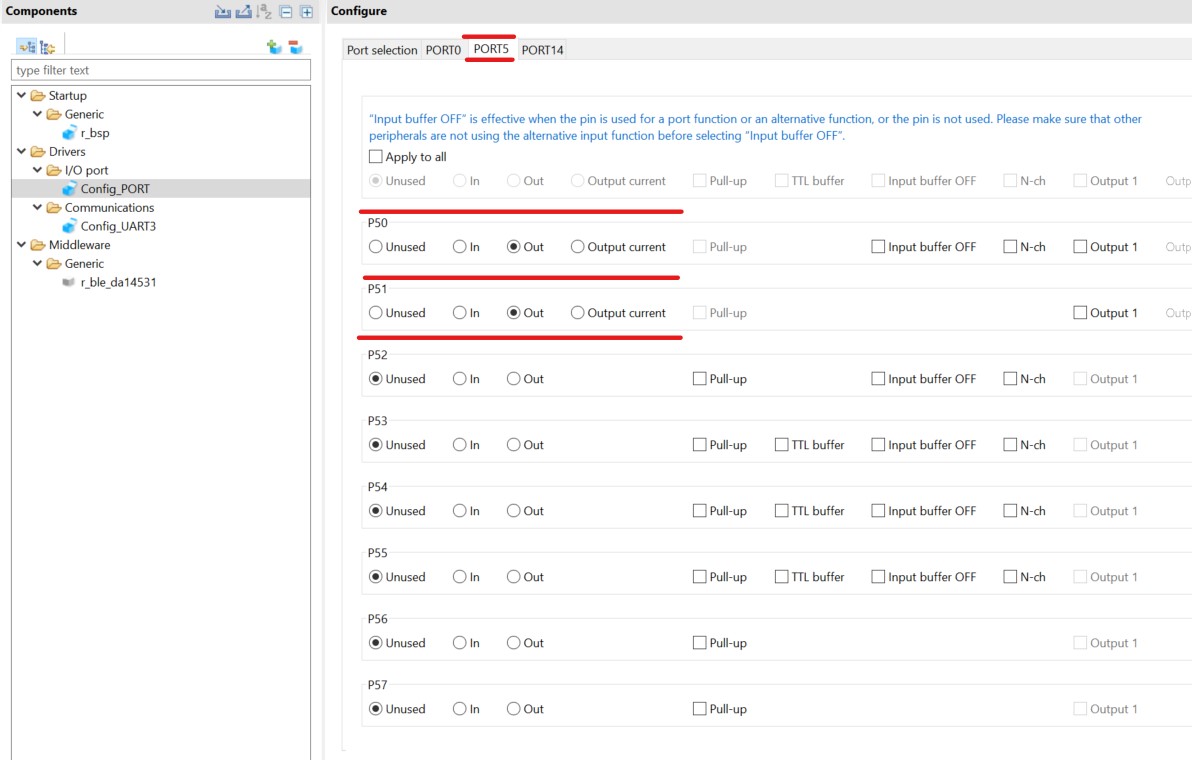
Figure 22 PORT5 Communication Module
Configure PORT14 as follow:
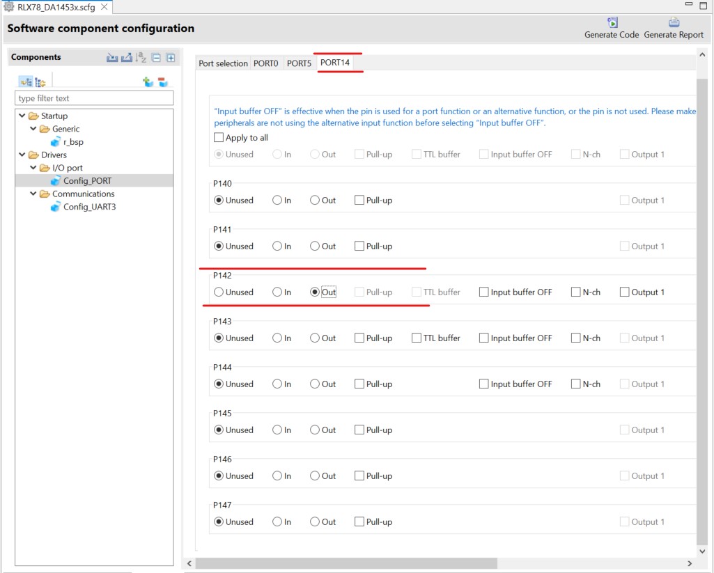
Figure 23 PORT14 Communication Module
Setup BLE module. Select Components tab in the Smart Configurator. Click Add Components button.
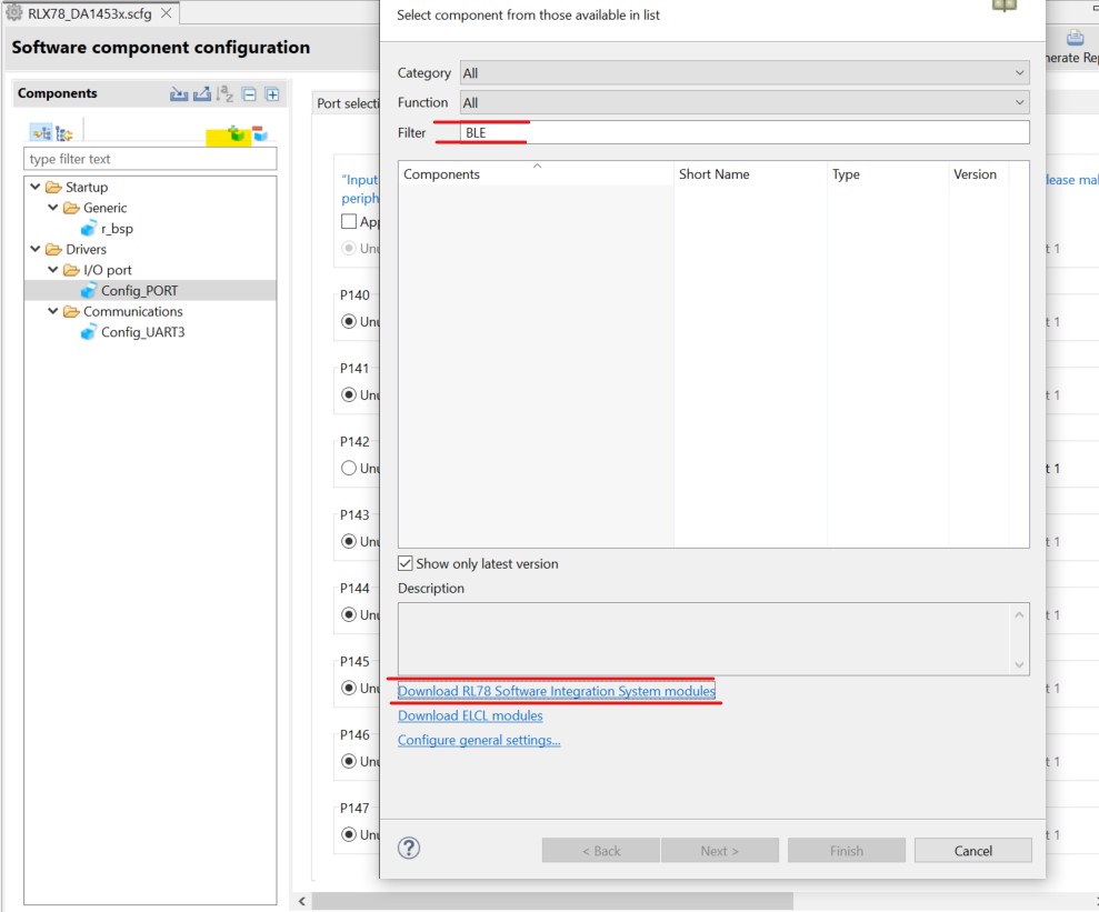
Figure 24 Component Selection
Select the following, and click Download:
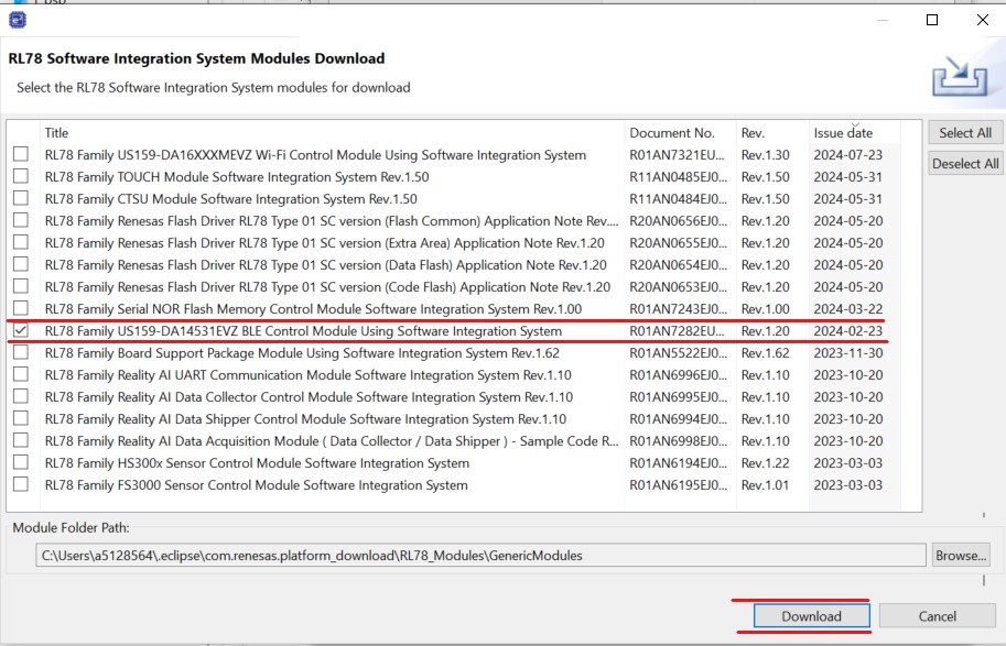
Figure 25 Download BLE Module
Click Add Components button to add the BLE module and click Finish button on the window.
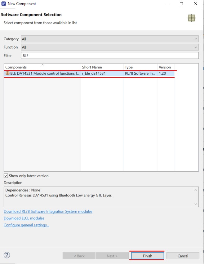
Figure 26 Add BLE Module
Important
To update the BLE module, you need to place the new module folder under C:\Users\a5128564\.eclipse\com.renesas.platform_download\RL78_Modules\GenericModules The lastest BLE module V1.3 could be download from the Here.
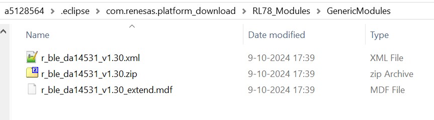
Figure 27 New BLE Module added
Select the BLE module r_ble_da14531 set the following properties:
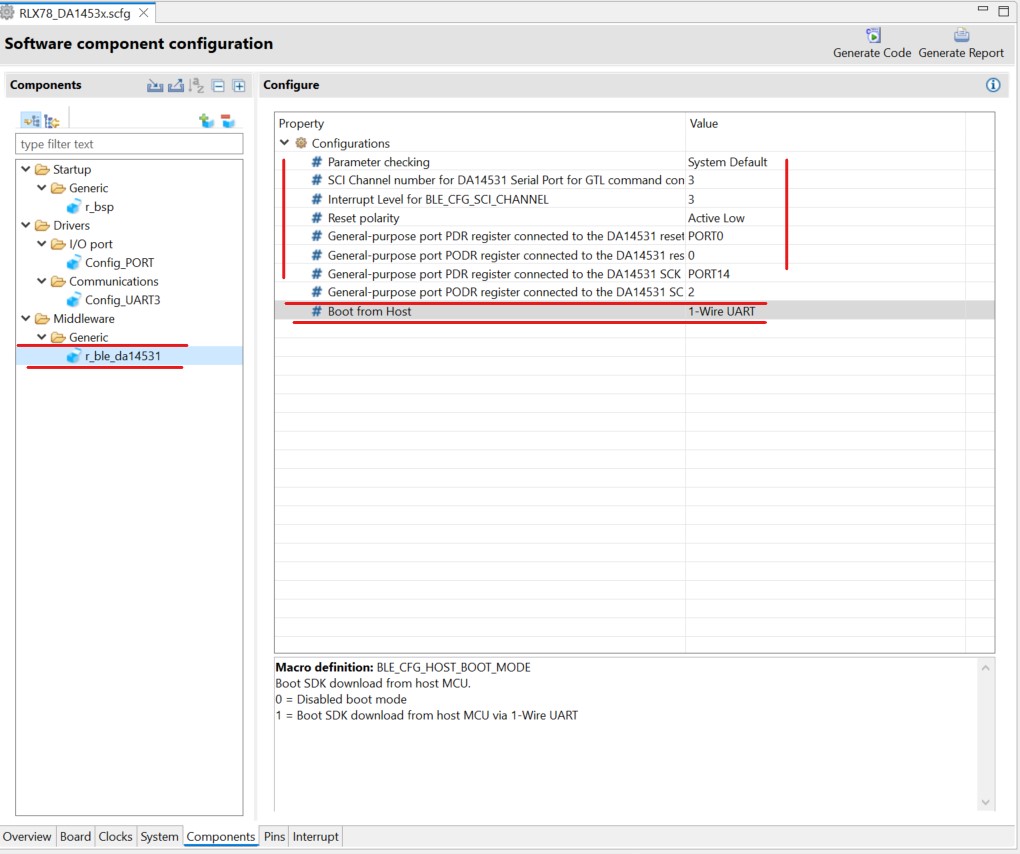
Figure 28 Add BLE Module configuration
Important
When using the DA14535 PMOD, 2 wire UART could be selected
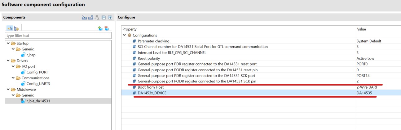
Figure 29 BLE Module configuration for 2 wire UART and DA14535
The RL87 Configuration for this section is now complete. Apply changes to the project source by clicking the Generate Project Content button in the top-right corner of the Configurator window.
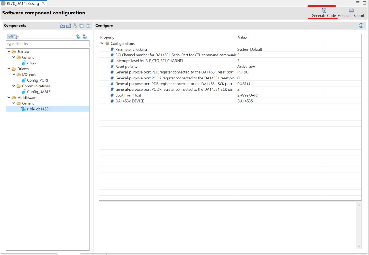
Figure 30 Generate Project Content
Some extra modules are needed to be included in the project workpace, you can get them from Here and place them under
srcfolder.
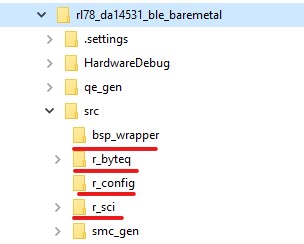
Figure 31 BLE wrapper added
Open the Project Settings, go to Tool Settings -> Compiler -> Source and add these paths below for the new modules:
"${workspace_loc:/${ProjName}/src/bsp_wrapper}"
"${workspace_loc:/${ProjName}/src/r_byteq}"
"${workspace_loc:/${ProjName}/src/r_sci}"
"${workspace_loc:/${ProjName}/src/r_config}"
4.2. Profile development with QE for BLE
This section describes how to design QE for BLE profile. QE for BLE can be used to design GATT profiles as well as to configure GAP roles and parameters for Bluetooth LE. With the QE profile configurator you can set up your device name and enable broadcasting.
From the menu bar select Renesas Views -> Renesas QE and then R_BLE_Custom Profile RA, RE, RX (QE) option.
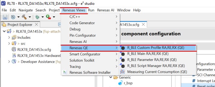
Figure 32 QE BLE
Set the Project to the name of your project and set the Module type to DA1453x.
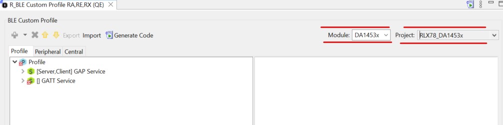
Figure 33 QE BLE module Configuration
Important
You may note that there already exist a couple of services. These are descriptive services that exist in most commercial profiles.
The R_BLE Custom Profile RA (QE) view has 3 main tabs:
The Profile tab allows the creation of your profile. Many of the SIG adopted profiles and services are present here, as well as the ability to generate custom ones.
The Peripheral tab allows you to easily view and change what data is transmitted in your advertising packets and scan responses. These are values exposed when the device acts as a Peripheral.
The Central tab allows you to set your scan and connection parameters, as well as scan filters. These values are used when the device is acting as a Central.
Go to the Peripheral tab indicated below. Here you can change what data the connectable advertising packets contain. Since we will not be using the device as a central, we will disregard the central tab.
Click the check box beside Local Name to enable it.
Then click Local Name itself, this will open the settings for the element.
Enter a name that is unique to your application, for example: DA14531-RL78-BLE
Select Advertising Parameter and set the Slow Advertising Interval to 100.0ms.
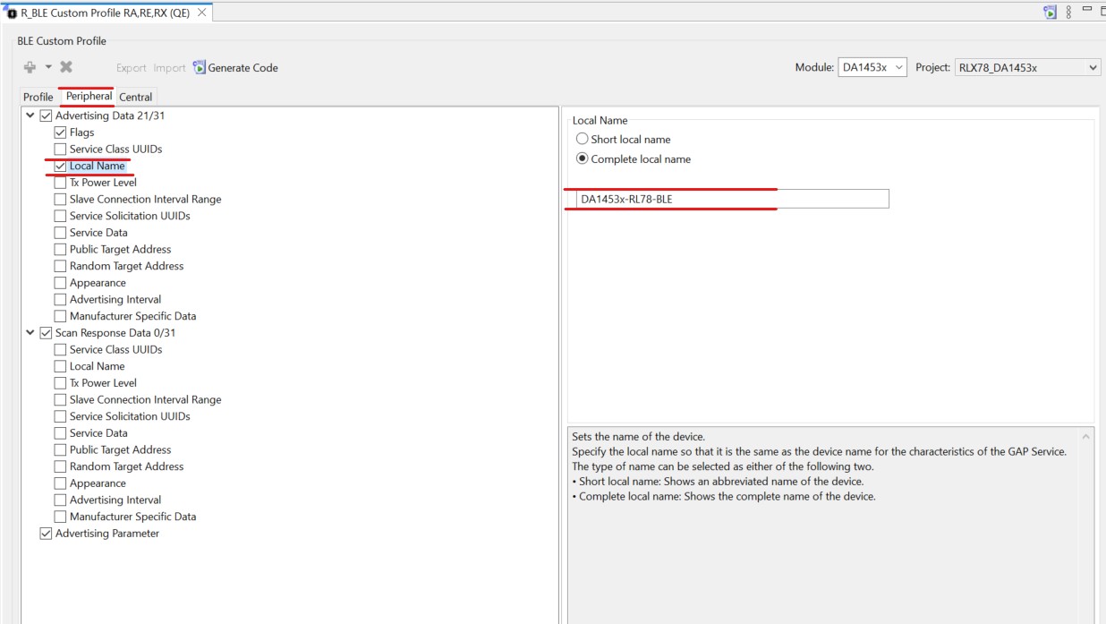
Figure 34 Peripheral tab Configuration
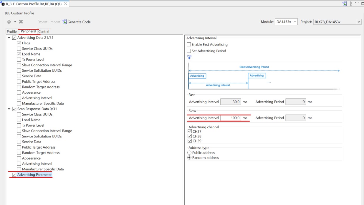
Figure 35 Peripheral tab Configuration advertising interval
4.3. QE GATT Profile
This section describes how to use the QE profile configurator to set up your SIG profile and generate the necessary source code.
In the QE tool, click back to the Profile tab.
You will notice the GAP service defaults to have both Server and Client configurations active, but the GATT service has a red X on it as shown in Figure 33. Since we will be using the device as a GATT server, you will need to enable this option for the GATT Service.
Click the GATT Service to select it, then click the Customize button in the panel to the right.
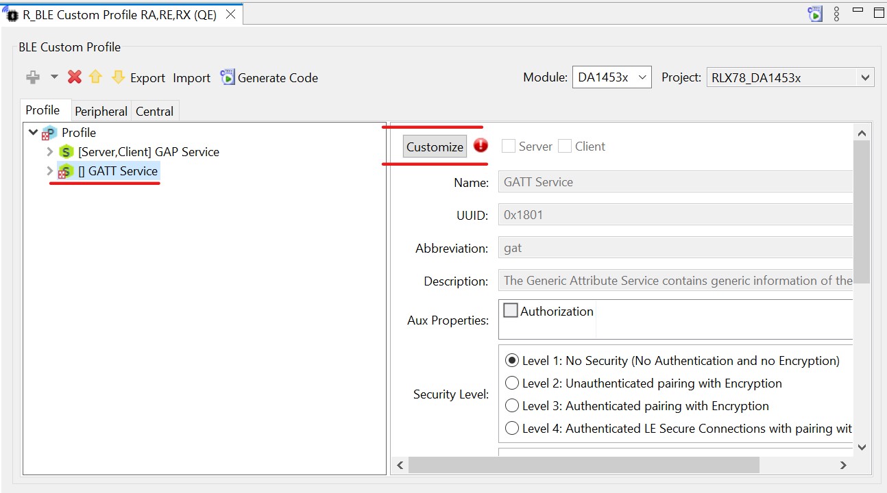
Figure 36 GATT service
Note that this will rename the service to GATT Service2. Delete the number 2 and check the box for Server above the name. You will notice the error symbol goes away.
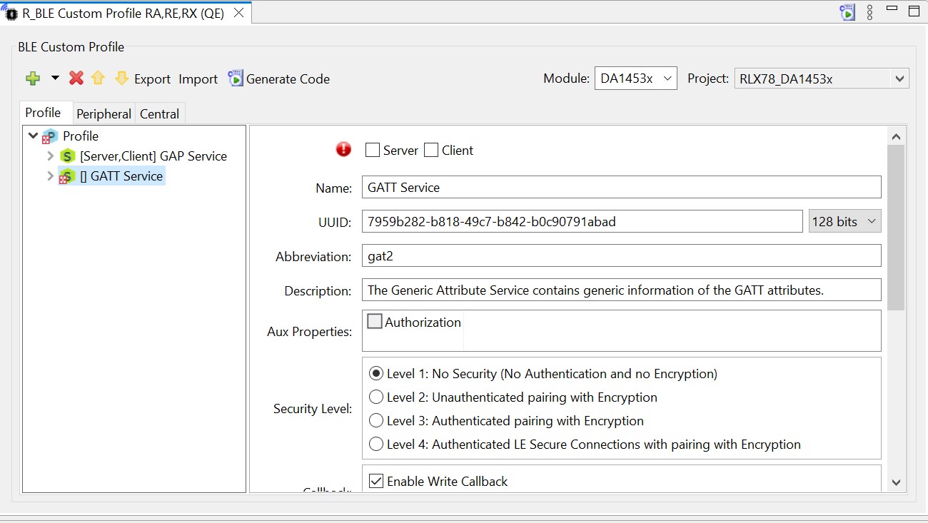
Figure 37 GATT service Enabled
To add a new service. Highlight the profile by clicking the cyan Profile button, then click the green plus above it.
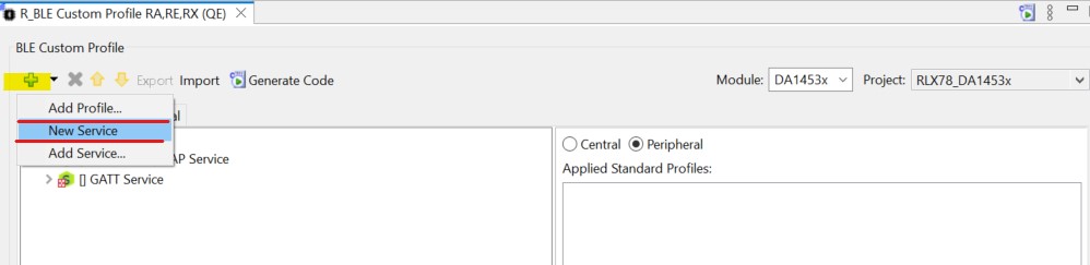
Figure 38 Add GATT service
When you click to customize, you will be prompted to enter in all the necessary information for your service
Rename the service “RL78 IO Control” and give it the abbreviation “evkioctrl” so we can easily identify this in our code.
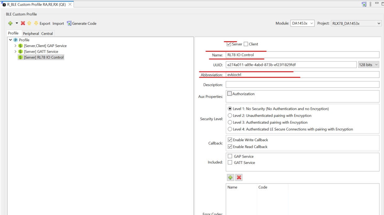
Figure 39 RL78 IO Control
Important
Note that a UUID is already pre-generated, you may change this if you wish but for now we will go ahead and accept whatever was randomly generated.
Now we will add new characteristic to the service we just created.
Set the Name to “LED Control”, the Abbreviation to “ledctrl”, the Properties to Read and Write.
Ensure DBSize is 1 as we will be using a 1-byte container to hold this value.
As our value will be initialized to 0, ensure Value is set to 0x00. At this point verify your screen looks as below:
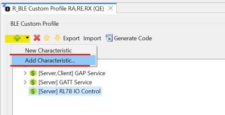
Figure 40 Alert Level characteristics
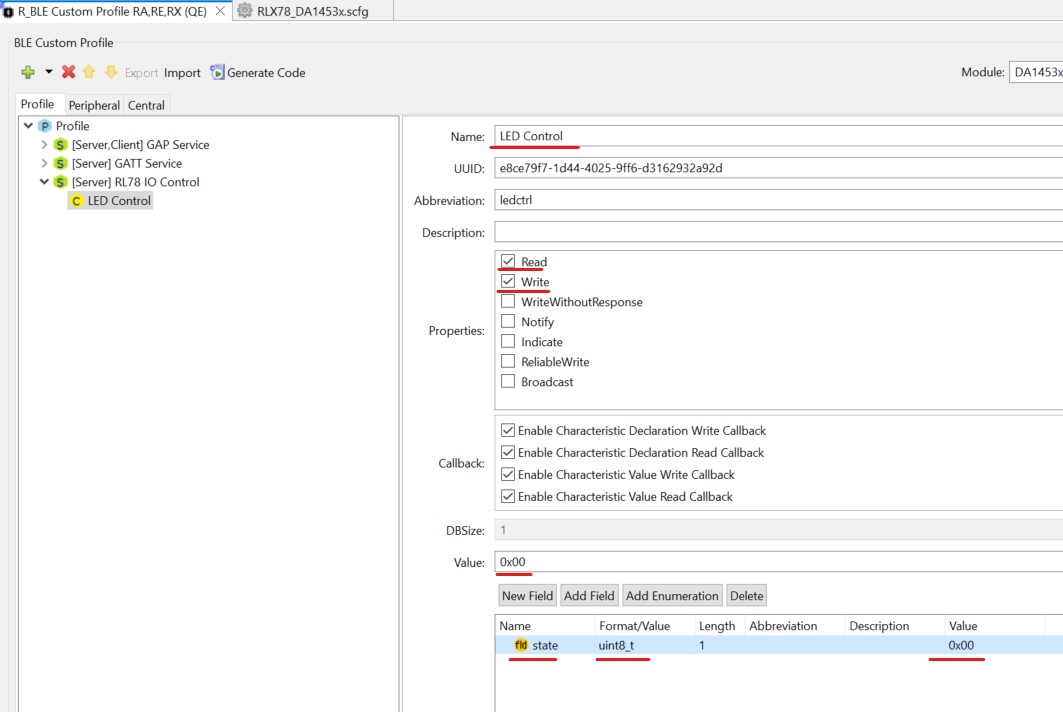
Figure 41 LED Control characteristics
Save the changes and then select Generate Code, necessary Include files will be added to the project
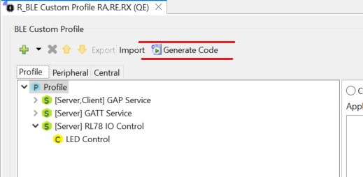
Figure 42 QE BLE generate code
Once complete, the generated files should be listed in the console
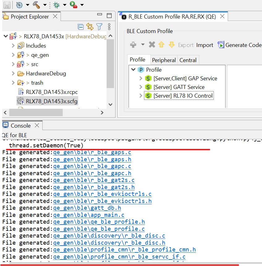
Figure 43 QE BLE code generation console
4.4. Source Code Modifications
This section steps through adding an application layer to the code generated by the smart configurator. The code we will insert is simple but would be the foundation for building out your entire project.
Note
First you need to ensure that the file qe_gen\ble\app_main.c has been generated.
In the file
qe_gen/ble/app_main.c, Add macro definitions:
/******************************************************************************
 User macro definitions
*******************************************************************************/
/* Start user code for macro definitions. Do not edit comment generated here */
#define GPIO_PORT(x, y)           (( P ## x ## _bit.no ## y ))
/* End user code. Do not edit comment generated here */
Update the ble_init() in the app_main function:
/* Initialize BLE and profiles */
if (BLE_SUCCESS == ble_init())
{
  GPIO_PORT(0, 2) = 1;
  GPIO_PORT(5, 0) = 1;
  GPIO_PORT(5, 1) = 1;
}
else
{
  GPIO_PORT(5, 0) = 1;
}
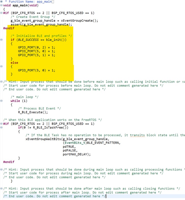
Figure 44 ble_init code update
Important
The API file, in our case r_ble_evkioctrls.h, contains all the functions and enums
necessary to interface with and control a GATT service. In this case the file provides the
interface for our Target Board IO control (abbreviation evkioctrls) service.
This file will be broken down into separate sections for each of the services characteristics, and one additional section for enumerations and generic functions.
Since this characteristic is enabled only for read and write it’s functions are pretty simple. There is a get function and a set function. These allow an interface with the characteristic value in the database.
The only callback we are interested in at this time is
evkioctrls_cb(), locate this function (around line 358). The other callbacks are very useful for understanding what events are happening inside the BLE stack, although they are beyond the scope of this document. Modify the callback function to have the following code inqe_gen/ble/app_main.c
/******************************************************************************
 * Function Name: evkioctrls_cb
 * Description  : Callback function for RL78 IO Control server feature.
 * Arguments    : uint16_t type -
 *                  Event type of RL78 IO Control server feature.
 *              : ble_status_t result -
 *                  Event result of RL78 IO Control server feature.
 *              : st_ble_servs_evt_data_t *p_data -
 *                  Event parameters of RL78 IO Control server feature.
 * Return Value : none
 ******************************************************************************/
static void evkioctrls_cb(uint16_t type, ble_status_t result, st_ble_servs_evt_data_t *p_data)
{
/* Hint: Input common process of callback function such as variable definitions */
/* Start user code for RL78 IO Control Server callback function common process. Do not edit comment generated here */
/* End user code. Do not edit comment generated here */
   uint8_t state;

   switch(type)
   {
   /* Hint: Add cases of RL78 IO Control server events defined in e_ble_evkioctrls_event_t */
   /* Start user code for RL78 IO Control Server callback function event process. Do not edit comment generated here */
   case BLE_EVKIOCTRLS_EVENT_LEDCTRL_WRITE_REQ:
   {
      if (BLE_SUCCESS == result)
      {
         state = *(uint8_t *)p_data->p_param;
         if (state == 0x00)
         {
            GPIO_PORT(5, 0) = 1;
         }
         else
         {
            GPIO_PORT(5, 0) = 0;
         }
      }
   }
   break;
   case BLE_EVKIOCTRLS_EVENT_LEDCTRL_READ_REQ:
   {
      if (BLE_SUCCESS == result)
      {
         state = GPIO_PORT(5, 0);
         R_BLE_EVKIOCTRLS_SetLedctrl(&state);
      }
   }
   break;
   default:
      break;


      /* End user code. Do not edit comment generated here */
    }
}
- In e2 studio project explorer, open the file
qe_gen/ble/profile_cmn/r_ble_servs_if.cincluding the R_BLE_SERVS_GetCharfunction and add the yellow highlighted code, resulting in the code shown below:
- In e2 studio project explorer, open the file
st_ble_gatt_value_t gatt_value = {0};
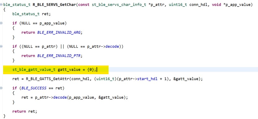
Figure 45 R_BLE_SERVS_GetChar code update
In e2 studio project explorer, open the file
src\[Project name].cincluding the main function and add the yellow highlighted code, resulting in the code shown below:
#include "r_smc_entry.h"
extern void app_main(void);
int main (void);

int main(void)
{
   EI();
   app_main();
   while(1)
   {
      R_BSP_SoftwareDelay(1000, BSP_DELAY_MILLISECS);
   }
   return 0;
}
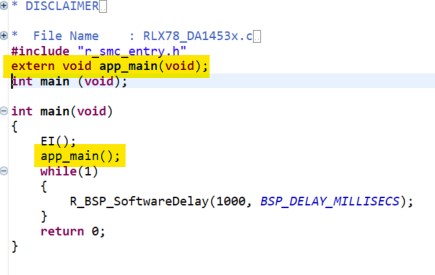
Figure 46 project name C file code update
in
src/smc_genChange the interrupt vectors inConfig_UART3_user.cby adding two lines as following:
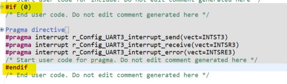
Figure 47 Config_UART3_user.c code update
4.5. Building and running the application
Now that the application is complete, you can build and run it on the RL78-G23-128p board. The toolchain will report compilation and build status to the console pane in the lower-right corner of e2 studio. When the build has completed, it should confirm that there are zero errors.
Warning
when you compile the project the compiler reports some warnings, You may ignore them. Some of them are dure to the compiler license.
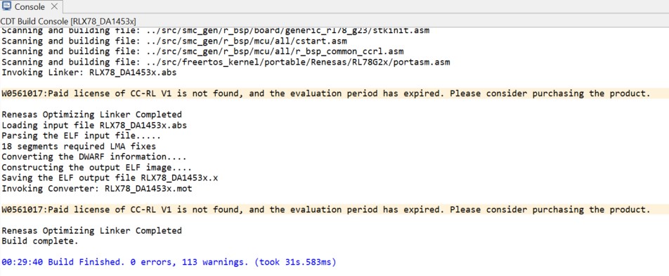
Figure 48 Build the application console
Create the project debug configuration
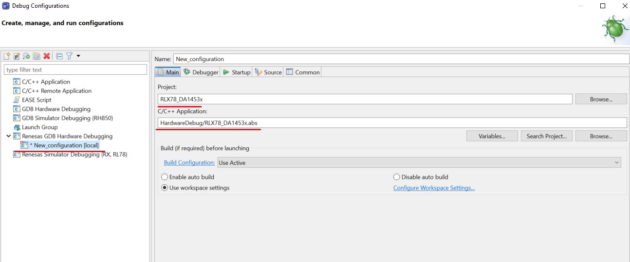
Figure 49 Create the debug configuration
The application is now ready to be programmed and run on the RL78-G23-128p board. board. Press the “bug” icon to begin the debug session.