4. Launch e2 studio and create the FSP application
Important
Follow the links below to access and download the pre-configured software examples for each hardware platform:
4.1. create the Renesas RA C/C++ Project
If you have not done so already, download and install FSP 5.4.0. Additionally, if you have not yet installed the QE BLE Tool you can do that now by following these Instructions.
Note
In this section a Renesas EK-RA6M4 board is used as the Host Renesas microcontroller, this can be replaced by almost any other Renesas microcontroller. Check the Target Devices tab for supported MCUs. If you are considering for instance to use the EK-RA6M5 there are just 2 changes need to be done. Please refer to:
And the note at the end of the section Section 4.5.
Next, Launch e2 studio. e2 studio can be launched from the Windows start menu or directly from the FSP folder. If you have multiple versions of e2 studio installed, please make sure to launch the version of e2 studio that is specified in the prerequisites section. In the Eclipse Launcher window, specify the destination for the new workspace. It is recommended to keep the path simple and avoid using spaces.
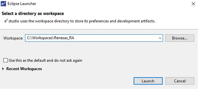
Figure 8 Eclipse Launcher window
Click Launch to start e2 studio in the specified path. When prompted, log into your My Renesas account or click Cancel to dismiss the pop up window asking for permission to log and report usage (it will remain disabled). Select No when prompted for setting up a password hint.
The welcome screen may show inside the new workspace. It can be dismissed by clicking on the Hide button in the top-right corner.
Figure 9 Hide button in the top-right corner
Go to File -> New and select C/C++ Project.
In the new project wizard window, select Renesas RA C/C++ Project and click Next
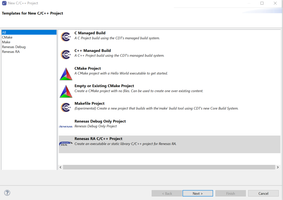
Figure 10 Renesas RA C/C++ Project
Specify a project name and Click Next.
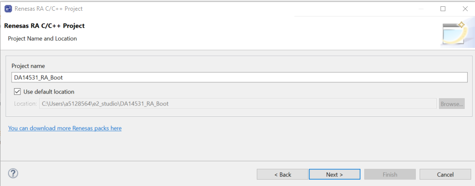
Figure 11 Project name
Select FSP version 5.3.0 and Board EK-RA6M4. The correct device will be selected automatically based on the board that was chosen. The toolchain version should be set to 13.2.1arm-13-7. Click Next.
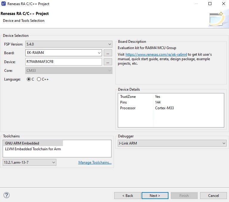
Figure 12 FSP version
Important
In this section a Renesas EK-RA6M4 board is used as the Host Renesas microcontroller, this can be replaced by almost any other Renesas microcontroller. Check the Target Devices tab for supported MCUs.
Select the project type as Flat (Non-TrustZone) Project and select Next.
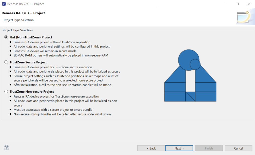
Figure 13 Flat Project
In the next window, select FreeRTOS (v10.6.1+fsp.5.3.0) from the RTOS selection drop down menu and select Next.
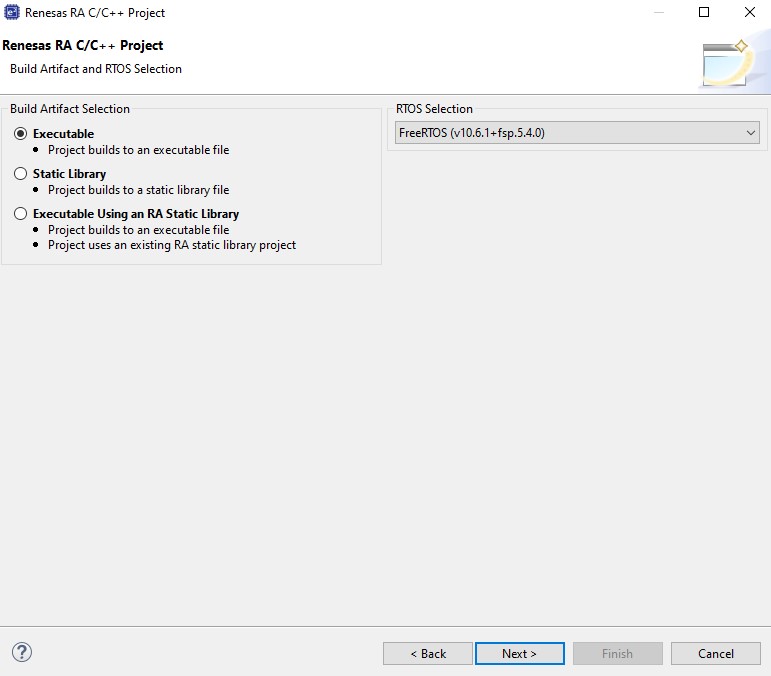
Figure 14 RTOS selection
On the final page of the wizard select FreeRTOS – Minimal – Static Allocation and click Finish.
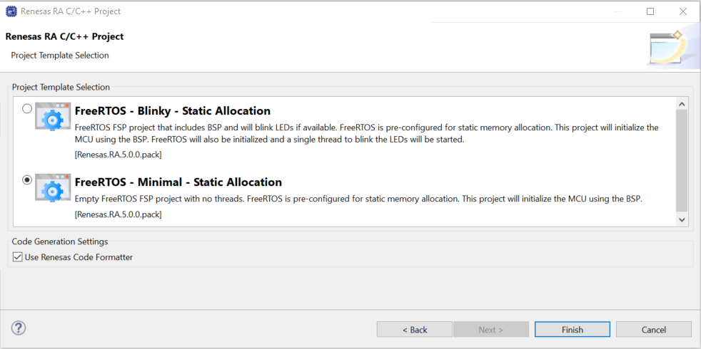
Figure 15 Minimal – Static Allocation selection
If prompted to open the Configuration perspective, click Open Perspective.
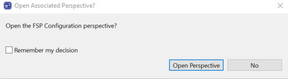
Figure 16 Open Perspective
e2 studio will switch to a layout optimized for developing Renesas RA projects. Select the BSP tab at the bottom of the RA Configuration pane visible in the middle. Select the Properties tab and in the RA Common section set the heap size to 0x800 (this is the heap used by standard library functions).
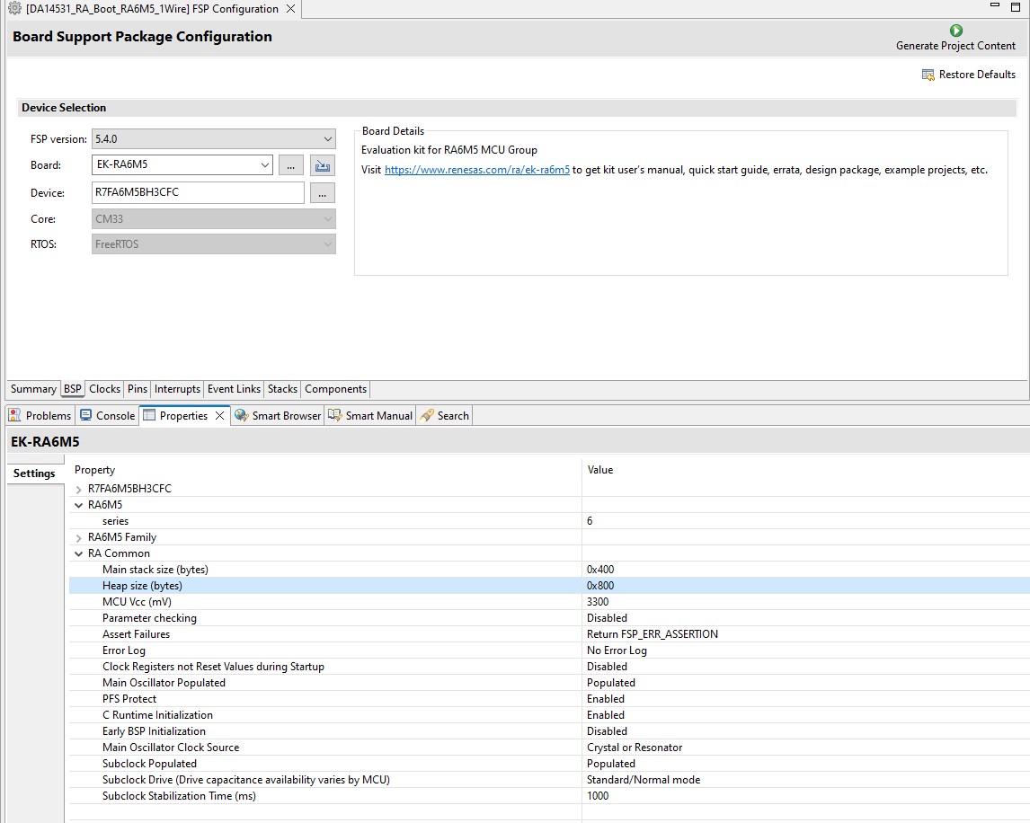
Figure 17 Heap size selection
4.2. Adding Bluetooth LE Communications
In this section Bluetooth LE Communications is added to the project. In case the RA configuration screen was closed previously, bring up the RA Configuration screen by double-clicking configuration.xml in the Project Explorer pane. Then select the FSP Configuration option in the top right corner.
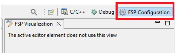
Figure 18 FSP configuration screen
Now select the Stacks configuration tab, this will be used for most of this document. It allows you to quickly create and configure threads, RTOS objects and driver/middleware instances.
Now add a thread for the application. Click on New Thread and a new thread will appear, This thread will be used by the DA1453x GTL Middleware.
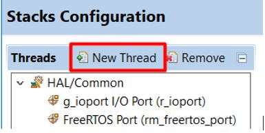
Figure 19 BLE thread selection
Select the Properties tab. It can be found in the lower-left pane, directly under the Project Explorer. In the Thread section, edit the new thread properties to match the configuration that is shown below:
Symbol ble_thread
Name BLE Thread
Stack size (bytes) 2048
Priority 2
Then navigate to Common -> General and set the following properties:
Use Mutexes Enabled
Use Recursive Mutexes Enabled
Now expand Optional Functions and set the following properties:
xTimerPendFunctionCall() Function Enabled
The DA1453x middleware uses heap memory to create tasks and queues and so dynamic memory allocation needs to be enabled. Expand Common and then Memory Allocation. Change following properties:
Support Dynamic Allocation Enabled
Total Heap Size 0x800
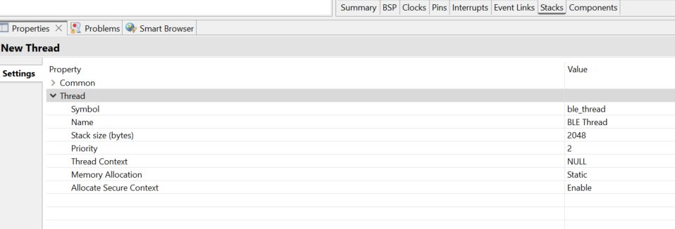
Figure 20 BLE thread configuration
Select HAL/Common on the Threads list and click on New Stack. From the menu select RTOS -> FreeRTOS Heap 4.
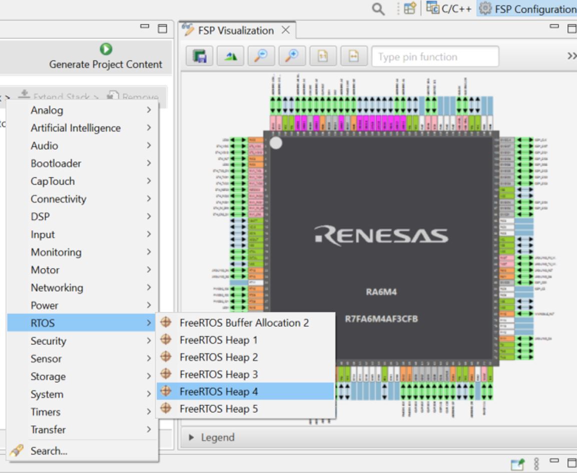
Figure 21 FreeRTOS heap 4 selection
Select the BLE Thread and open the New Stack menu and select Networking -> GTL BLE Abstraction
(rm_ble_abs_gtl)
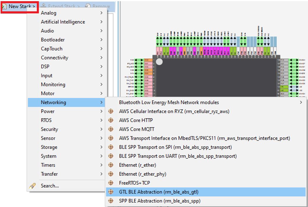
Figure 22 GTL BLE abstraction selection
A new module stack will be added to the HAL/Common Stacks context
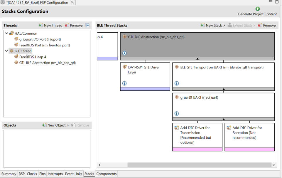
Figure 23 BLE module stack
Select the DA14531 GTL Driver Layer, go to the Properties tab to set the following properties:
Reset Polarity Active Low
Reset Port 07
Reset Pin 08
RTS Port 04
RTS Pin 12
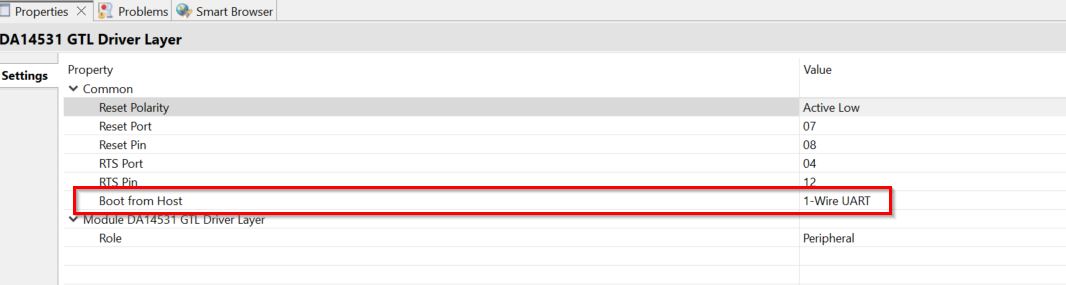
Figure 24 Pmod™ Pins config for RA6M4-EK
For 2 Wire UART configuration:
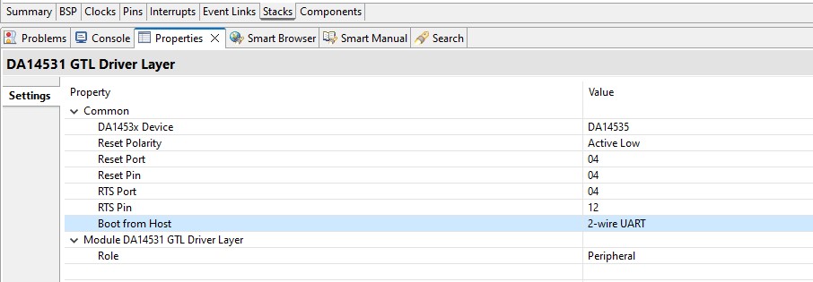
Figure 25 Pmod™ Pins config (2 Wire UART) for RA6M4-EK
Note
For the RA6M5-EK the reset pin port for PMOD2 is P404. Refer to the following figure
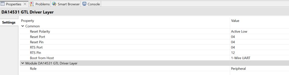
Figure 26 Pmod™ Pins config for RA6M5-EK
Warning
Enable the option to boot DA14531 from host MCU through 1-Wire UART (disabled by default)
The DA14531 Pmod™ module will be connected on the Pmod™ 2 of the RA6M4 dev kit, when considering to Use another MCU, all the steps that we mentioned earlier are the same, you just need to correctly configure the Reset PIN for the Pmod™ on that Dev kit
Navigate to Pins tab inside RA Configuration window.
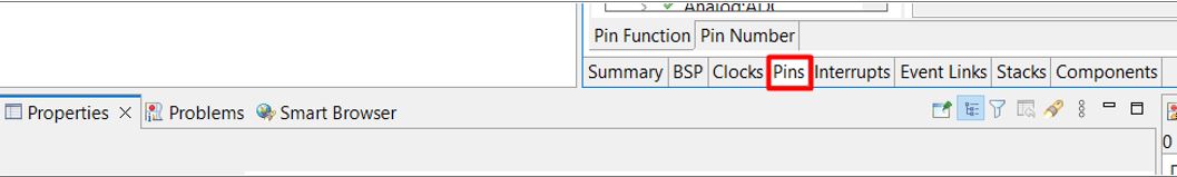
Figure 27 Pins tab inside RA Configuration
On the left side, expand Peripherals and Connectivity:SPI groups and select SPI1. Choose Disabled from the Operation Mode drop-down menu. Since the pins are multiplexed, we disable SPI1 so we can reuse these pins for UART communication.
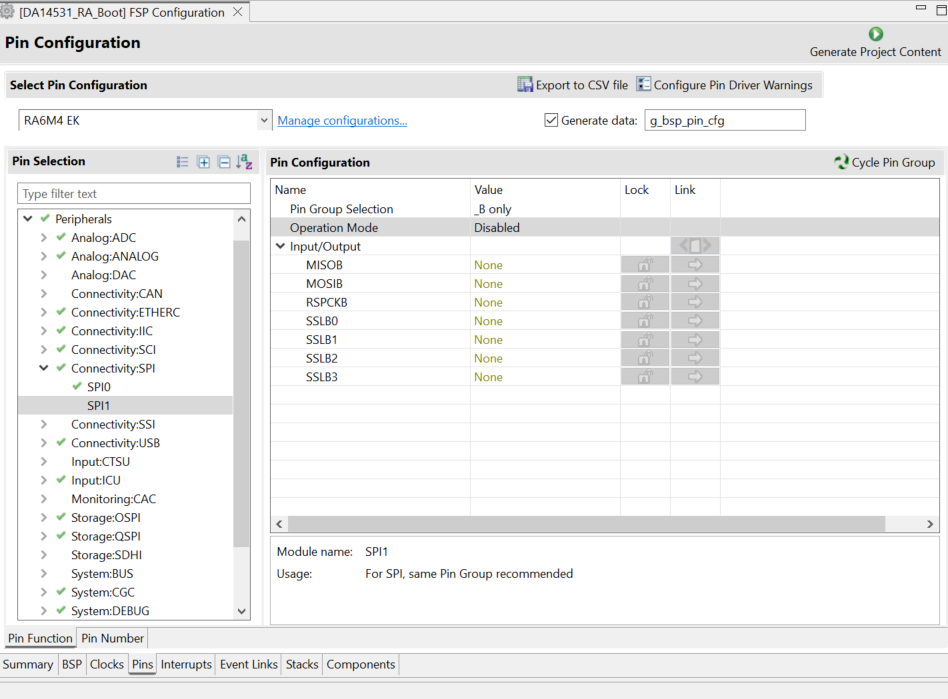
Figure 28 SPI1 Configuration
Under Peripherals -> Connectivity:SCI select SCI0. Set the Operation Mode to Asynchronous UART. TXD0 and RXD0 pins will be set automatically to P411 and P410.
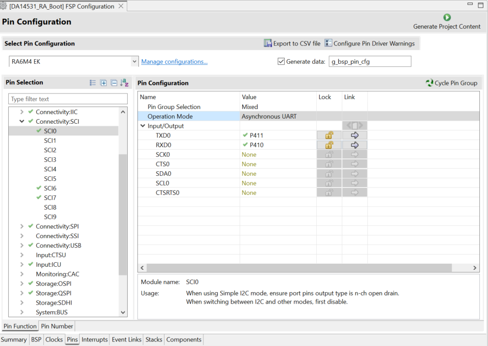
Figure 29 SCI0 Configuration
Under Ports -> P4 select P412. Set the Operation Mode to Output mode (Initial Low).

Figure 30 Pmod™ CLK Configuration
The RA Configuration for this section is now complete. Apply changes to the project source by clicking the Generate Project Content button in the top-right corner of the Configurator window.
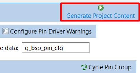
Figure 31 Generate Project Content
The RA Configurator will extract all the necessary drivers and generate the code based on the configurations provided in the Properties tab.
4.3. Profile development with QE for BLE
This section describes how to design QE for BLE profile. QE for BLE can be used to design GATT profiles as well as to configure GAP roles and parameters for Bluetooth LE. With the QE profile configurator you can set up your device name and enable broadcasting.
From the menu bar select Renesas Views -> Renesas QE and then R_BLE_Custom Profile RA, RE, RX (QE) option.
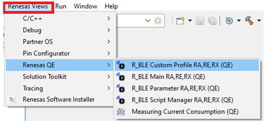
Figure 32 QE BLE
Set the Project to the name of your project and set the Module type to DA1453x.
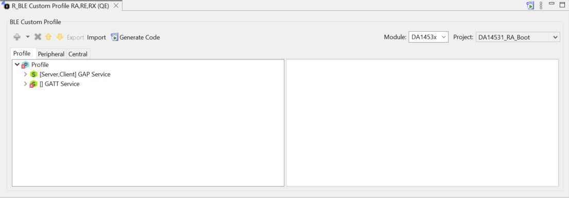
Figure 33 QE BLE module Configuration
Important
You may note that there already exist a couple of services. These are descriptive services that exist in most commercial profiles.
The R_BLE Custom Profile RA (QE) view has 3 main tabs:
The Profile tab allows the creation of your profile. Many of the SIG adopted profiles and services are present here, as well as the ability to generate custom ones.
The Peripheral tab allows you to easily view and change what data is transmitted in your advertising packets and scan responses. These are values exposed when the device acts as a Peripheral.
The Central tab allows you to set your scan and connection parameters, as well as scan filters. These values are used when the device is acting as a Central.
Go to the Peripheral tab indicated below. Here you can change what data the connectable advertising packets contain. Since we will not be using the device as a central, we will disregard the central tab.
Click the check box beside Local Name to enable it.
Then click Local Name itself, this will open the settings for the element.
Enter a name that is unique to your application, for example: DA14531-FSP-BLE
Select Advertising Parameter and set the Slow Advertising Interval to 100.0ms.
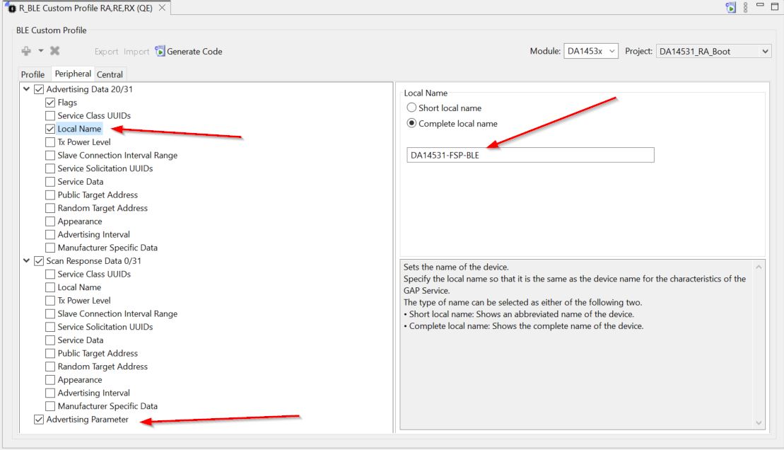
Figure 34 Peripheral tab Configuration
4.4. QE GATT Profile
This section describes how to use the QE profile configurator to set up your SIG profile and generate the necessary source code.
In the QE tool, click back to the Profile tab.
You will notice the GAP service defaults to have both Server and Client configurations active, but the GATT service has a red X on it as shown in Figure 33. Since we will be using the device as a GATT server, you will need to enable this option for the GATT Service.
Click the GATT Service to select it, then click the Customize button in the panel to the right.
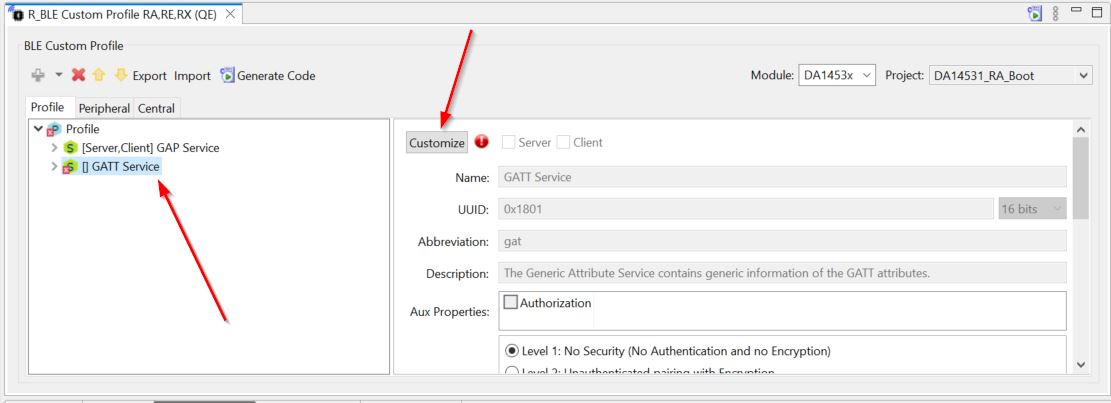
Figure 35 GATT service
Note that this will rename the service to GATT Service2. Delete the number 2 and check the box for Server above the name. You will notice the error symbol goes away.
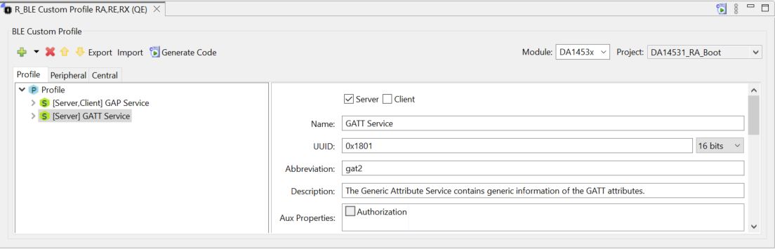
Figure 36 GATT service Enabled
To add a new service. Highlight the profile by clicking the cyan Profile button, then click the green plus above it.
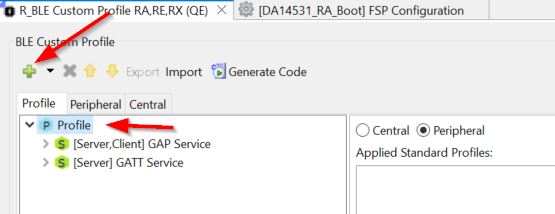
Figure 37 Add GATT service
Important
Next, you can add some of the profiles and services that have been adopted by the Bluetooth Special Interest Group (SIG). In this document we will select “Add Service” as we want to add service that has been already been defined
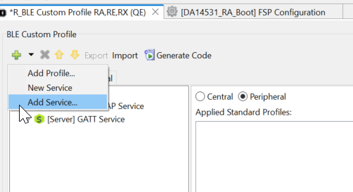
Figure 38 Select Add service
Select Immediate Alert Service
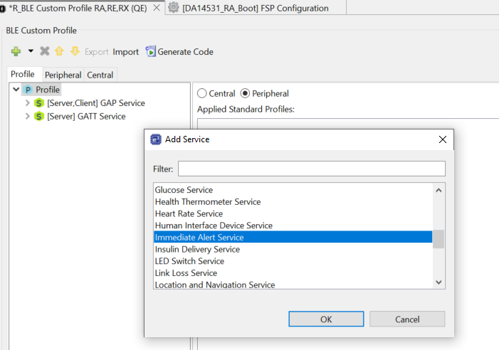
Figure 39 Immediate Alert Service
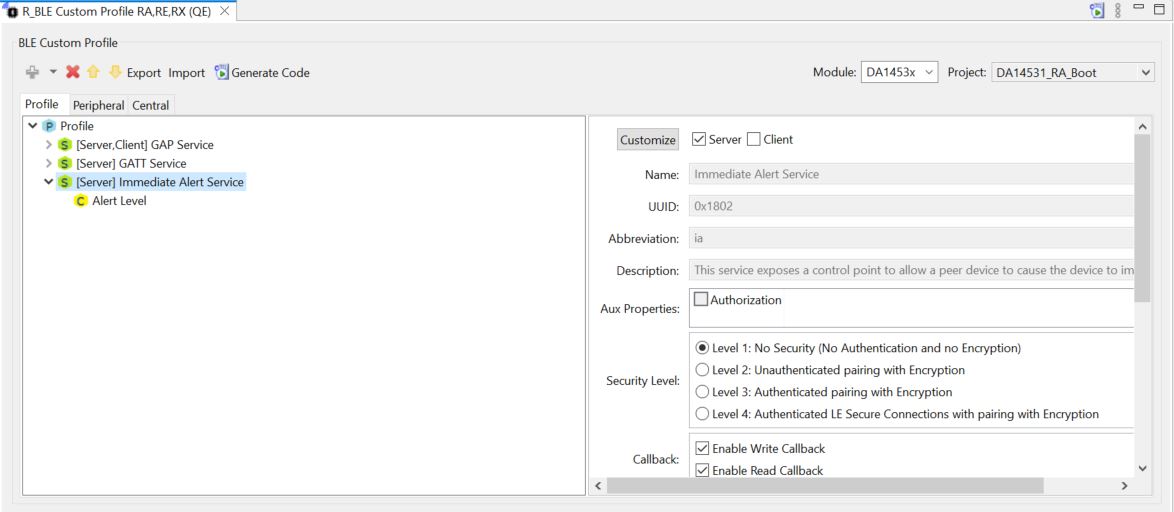
Figure 40 Immediate Alert Service Added
When you click to customize, you will be prompted to enter in all the necessary information for your service
Rename the service “RA6M4 IO Control” and give it the abbreviation “evkioctrl” so we can easily identify this in our code.
Important
Note that a UUID is already pre-generated, you may change this if you wish but for now we will go ahead and accept whatever was randomly generated.
When you have completed the service configuration, verify it looks similar to below:
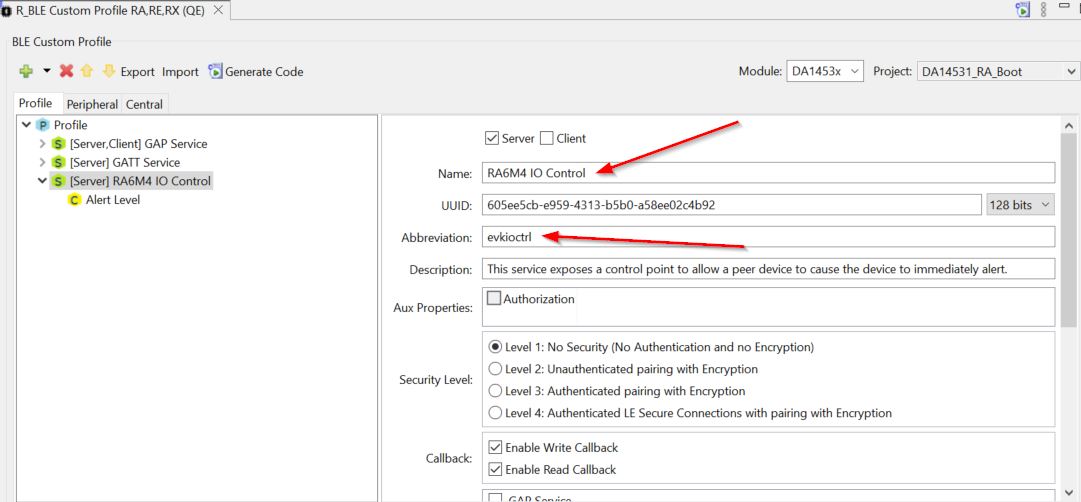
Figure 41 IO control service
Now we will edit our characteristics to the service we just created. click the yellow “C”. In the Properties box check the Read and Write boxes. This is so we can allow the client (our phone) to retrieve and set these values.
Set the Name to “LED Control”, the Abbreviation to “ledctrl”, the Properties to Read and Write.
Ensure DBSize is 1 as we will be using a 1-byte container to hold this value.
As our value will be initialized to 0, ensure Value is set to 0x00. At this point verify your screen looks as below:
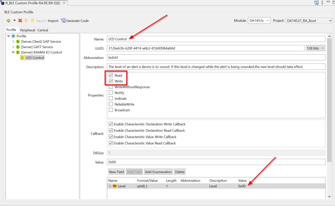
Figure 42 Alert Level characteristics
Save the changes and then select Generate Code, necessary Include files will be added to the project
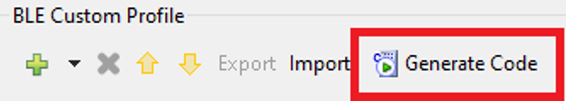
Figure 43 QE BLE generate code
Once complete, the generated files should be listed in the console
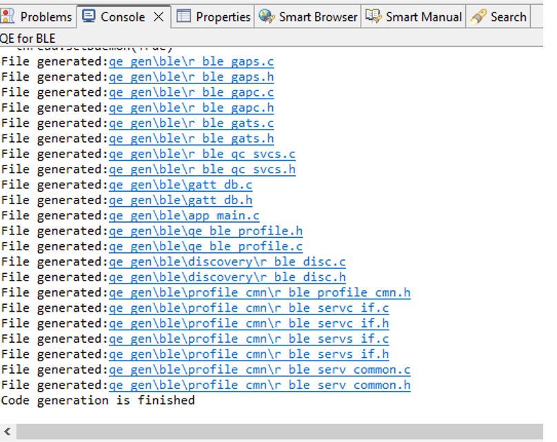
Figure 44 QE BLE code generation console
4.5. Source Code Modifications
This section steps through adding an application layer to the code generated by the smart configurator. The code we will insert is simple but would be the foundation for building out your entire project.
Note
First you need to ensure that the file qe_gen\ble\app_main.c has been generated.
In the file
qe_gen/ble/app_main.c, add header files that are required to access common components:
/******************************************************************************
 User file includes
*******************************************************************************/
/* Start user code for file includes. Do not edit comment generated here */
#include "qe_ble_profile.h"
#include "ble_thread.h"
/* End user code. Do not edit comment generated here */
Add a call to
app_mainto the ble_thread_entry in thesrc/ble_thread_entry.cfile
#include "ble_thread.h"

extern void app_main(void);

/* BLE Thread entry function */
/* pvParameters contains TaskHandle_t */
void ble_thread_entry(void *pvParameters)
{
    FSP_PARAMETER_NOT_USED (pvParameters);

    /* TODO: add your own code here */

    app_main();

    while (1)
    {
        vTaskDelay (1);
    }
}
Important
The API file, in our case r_ble_evkioctrls.h, contains all the functions and enums
necessary to interface with and control a GATT service. In this case the file provides the
interface for our Target Board IO control (abbreviation evkioctrls) service.
This file will be broken down into separate sections for each of the services characteristics, and one additional section for enumerations and generic functions.
Since this characteristic is enabled only for read and write it’s functions are pretty simple. There is a get function and a set function. These allow an interface with the characteristic value in the database.
The only callback we are interested in at this time is
evkioctrls_cb(), locate this function (around line 358). The other callbacks are very useful for understanding what events are happening inside the BLE stack, although they are beyond the scope of this document. Modify the callback function to have the following code inqe_gen/ble/app_main.c
static void evkioctrls_cb(uint16_t type, ble_status_t result, st_ble_servs_evt_data_t *p_data)
{
/* Hint: Input common process of callback function such as variable definitions */
/* Start user code for RA6M4 IO Control Server callback function common process. Do not edit comment generated here */
/* End user code. Do not edit comment generated here */

    switch(type)
    {
/* Hint: Add cases of RA6M4 IO Control server events defined in e_ble_evkioctrls_event_t */
/* Start user code for RA6M4 IO Control Server callback function event process. Do not edit comment generated here */

        case BLE_EVKIOCTRLS_EVENT_LEDCTRL_WRITE_REQ:
        {
            if (BLE_SUCCESS == result)
            {
                uint8_t Level = *(uint8_t *)p_data->p_param;
                if(Level == 0x00)
                {
                    R_IOPORT_PinWrite(&g_ioport_ctrl, BSP_IO_PORT_04_PIN_15,BSP_IO_LEVEL_LOW);
                }
                else
                {
                    R_IOPORT_PinWrite(&g_ioport_ctrl, BSP_IO_PORT_04_PIN_15,BSP_IO_LEVEL_HIGH);
                }
            }
        }
        break;

        default:
            break;

/* End user code. Do not edit comment generated here */
    }
}
Note
The control port for the LED1 (blue) in the RA6M5-EK is P006. If you are considering to use the this Evalution kit you need to replace in the previous code BSP_IO_PORT_04_PIN_15 by BSP_IO_PORT_00_PIN_06
4.6. Building and running the application
Now that the application is complete, you can build and run it on the EK-RA6M4 board.
Press the “hammer” icon to start building the project
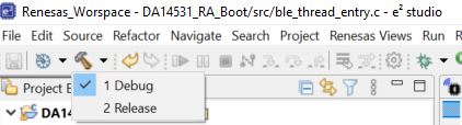
Figure 45 Build the application
The toolchain will report compilation and build status to the console pane in the lower-right corner of e2 studio. When the build has completed, it should confirm that there are zero errors.
Warning
when you compile the project the compiler reports some warnings, You may ignore them. Some callbacks are not updated and they are beyond the scope of this document.
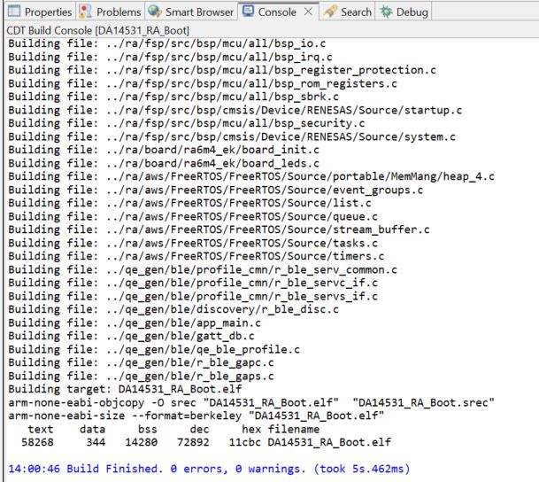
Figure 46 Build the application console
Create the project debug configuration
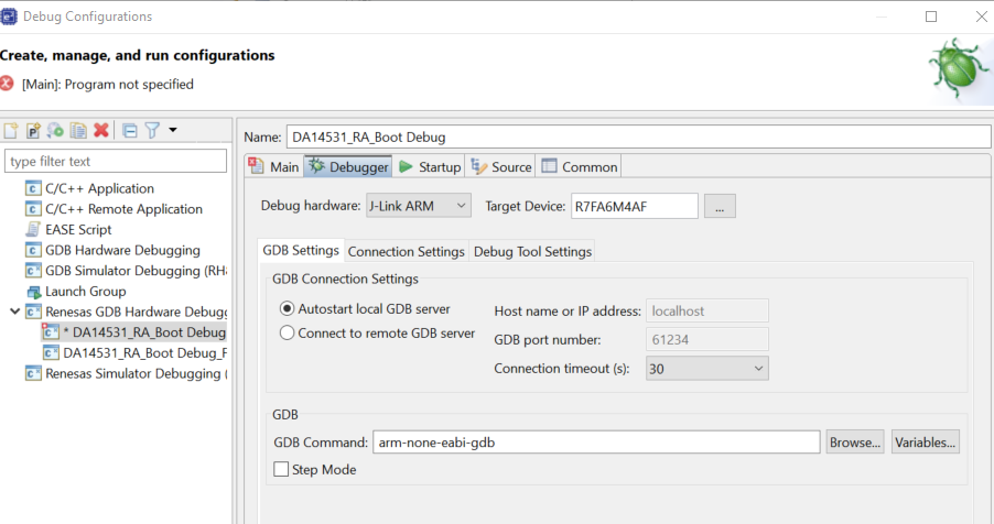
Figure 47 Create the debug configuration
The application is now ready to be programmed and run on the EK-RA6M4 board. Press the “bug” icon to begin the debug session.
Figure 48 Run the debug configuration
e2 studio will perform flash programming routines and prompt to switch to Debug perspective. Select the check box by Remember my decision and click Switch. LED5 near the debug USB port will blink while programming.
The debug session is now started, and the application is paused at its entry function
(Reset_Handler). Click the Resume button or press F8 on the keyboard to start the application.