5. User Guides
5.1. The BLE Framework
Figure 14 depicts the general architectural scheme used.
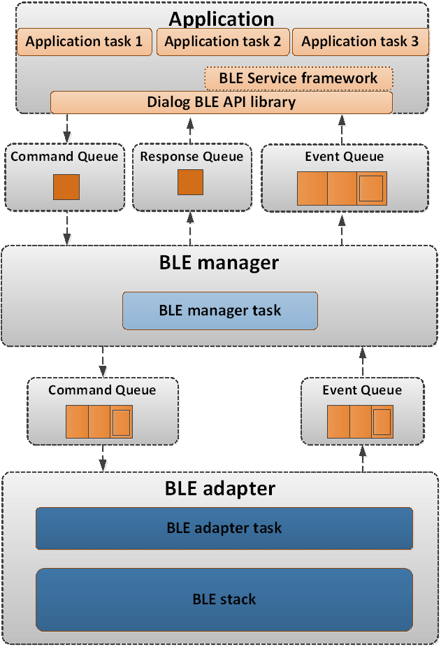
Figure 14 BLE Framework architecture
Using a top-down approach, the layers that build-up the BLE Framework functionality can be identified as the following:
The BLE service framework provides BLE services that the application can use “out-of-the-box”, using simple initialization functions and callbacks for the various BLE service events (like the change of an alert level attribute). The functionality of the BLE service framework is built on top of the Renesas BLE API library. The BLE service API header files can be found under
<SDK_ROOT_PATH>/sdk/interfaces/ble/services/include. The BLE service callbacks are executed by the application task that uses the BLE service framework.The Renesas BLE API is a set of functions that can be used to initiate BLE operations or respond to BLE events. The API header files can be found under the path
<SDK_ROOT_PATH>/sdk/interfaces/ble/api/include. The API functions can be used to send messages (commands or replies to events) to the BLE manager, either by directly calling the BLE manager command handler or by using queues between the application task and the BLE manager task. The BLE API is called in the context of the application.The BLE manager provides the interface to the BLE functionality of the chip. Only one application task must use the BLE functionality of the Renesas BLE API to interface with the BLE manager. Any other task need to send something to the BLE API, must defer it through the one task sending/receiving the BLE events.The BLE manager itself is a task (RTOS task) that stands between the application and the BLE adapter. The BLE adapter is the interface with the BLE controller running in the CMAC M0+ where the BLE stack is implemented. The BLE adapter itself is a separate (RTOS task).
The BLE adapter is the system task that provides the interface to the BLE Stack. It runs the BLE Stack internal scheduler, receives the commands or the replies to events from the BLE manager, and passes BLE events to the BLE manager. BLE core functionality is implemented by the BLE adapter task.
The BLE Stack is the software stack that implements both the BLE Host and the Low Energy (LE) controller (Link Layer). The BLE Host includes the Logical Link Control and Adaptation Protocol (L2CAP), the Security Manager Protocol (SMP), the Attribute Protocol (ATT), the Generic Attribute Profile (GATT) and the Generic Access Profile (GAP). The BLE Stack API header files, for the DA1459x, can be found under
<SDK_ROOT_PATH>/sdk/interfaces/ble/stack/<device_family>/include. The BLE Stack software is run under the BLE adapter’s task context.
Important
Secure Store Functionality (RED Compliance)
To support RED compliance, a secure store feature has been added to SDK10.1.6. This enhancement enables the BLE Manager to securely store bonding data in encrypted form within the embedded flash memory. Additionally, it provides a mechanism for user applications to securely store and retrieve encrypted sensitive data, ensuring protection against unauthorized access to external flash contents.
5.1.1. Developing BLE Applications
One of the main goals of the DA1459x SDK is to simplify the development of BLE applications and achieve a fast time to market. The DA1459x SDK separates the application logic from the BLE Stack implementation and provides a clean and powerful API to interact with the BLE capabilities of the device. The BLE API provides an easy way to configure the BLE device, start air operations and set up the attribute database of a GATT server. The BLE service API provides access to predefined Bluetooth SIG profiles with the definition of only a few callback functions.
The Proximity Reporter (pxp_reporter) application is the most typical of the BLE applications that are included in the DA1459x SDK. It is a complete and solid example of a BLE application developed on top of the DA1459x SDK. It uses both the Renesas BLE API and the BLE service framework to implement the functionality of a BLE profile.
However, it may not be the simplest example or the best starting point to become familiar with the development of a BLE application from scratch. Instead, there are BLE projects specifically created to serve as starting points for specific BLE applications such as beacons (ble_adv_demo) or specific roles such as a generic peripheral (ble_peripheral) or central (ble_central) device.
The goal of this section is to introduce the various options and examples that exist in the DA1459x SDK which can be used as building blocks for many applications. After a short introduction on where the API header files can be found, each section describes the functionality they implement along with guidance on how they differ from each other. This information is essential when developing a BLE application from scratch.
5.1.1.1. Updating BLE Application for User Data Secure Store Functionality
This section describes how to update a BLE application (e.g., pxp_reporter) to support User Data Secure Store functionality, which encrypts and stores secure data in flash memory using the AES-CTR algorithm The pxp_reporter example can be updated to demonstrate secure storage of user data. Specifically, it encrypts battery level measurements using the AES-CTR algorithm, stores them in the LOG partition of the embedded flash, and later decrypts the data to validate the storage process. This feature showcases how to securely store and retrieve sensitive information in compliance with RED.
How It Works:
Upon connection from a central device, the application periodically measures the battery level (default: every 60000 ms).
Each measurement is:
Encrypted using AES-CTR
Stored in the LOG partition
During decryption, the data is read back, decrypted using the correct counter, and printed for verification.
AES-CTR requires a unique counter for each encryption. The application uses the relative address in the LOG partition as the counter to ensure cryptographic security.
Encryption and decryption operations use the Device Unique Symmetric Key (DUSK), stored in the last slot of the User Data Encryption Keys Payload section in OTP. If not already generated, use generate_dusk command.
Enabling the Feature
This feature is disabled by default, To enable secure user data storage in your BLE application:
In custom_config_*.h, define:
#define USER_DATA_SECURE_STORE_ENABLE     (1)
#define dg_configUSE_HW_AES               (1)
#define dg_configCRYPTO_ADAPTER           (1)
To enable logging of the encrypted/decrypted values, add:
#define USER_DATA_SECURE_STORE_LOG_ENABLE (1)
#define CONFIG_RETARGET
5.1.2. The BLE API header files
5.1.2.1. Dialog BLE API
All demos and services API can be found in [Ref_03].
In most projects these API header files are symbolically linked to files located in
<SDK_ROOT_PATH>/sdk/interfaces/ble/api/include.
The API functions are declared across several header files depending on their functionality:
Common API (ble_common.h): Functions used for operations, not specific to a specific BLE device software component. For example:
Function |
Description |
|---|---|
ble_register_app() |
Register the application to the BLE Framework so that it can receive BLE event notifications. |
ble_enable() |
Enable the BLE module. |
ble_reset() |
Reset the BLE module. |
ble_central_start() |
Start the device as a BLE central. This is actually a helper function, since it uses API calls ble_enable() and ble_gap_role_set(). |
ble_peripheral_start() |
Start the device as a BLE peripheral. This is also a helper function that uses ble_enable() and ble_gap_role_set(). |
ble_get_event() |
Get a BLE event from the BLE event queue. |
ble_has_event() |
Check if there is an event pending at the BLE event queue. |
ble_handle_event_default() |
Used to define handling of events that are not handled by the added services or the application defined handlers. |
ble_read_tx_power() |
Read controller TX power |
ble_address_to_string() |
Convert bd_address to string |
ble_address_from_string() |
Convert string to bd_address |
ble_set_fem_voltage_trim() |
Set FEM Voltage GPIO values for a specific channel |
GAP & L2CAP APIs (ble_gap.h/ble_l2cap.h): Covers a wide range of operations, like
Device parameters configuration: device role, MTU size, device name exposed in the GAP service attribute, etc.
Air operations: Advertise, scan, connect, respond to connection requests, initiate or respond to connection parameters update, etc.
Security operations: Initiate and respond to a pairing or bonding procedure, set the security level, unpair, etc.
Function |
Description |
|---|---|
BLE device configuration |
|
ble_gap_role_get() |
Get the GAP role currently set. |
ble_gap_role_set() |
Set the device GAP roles (central, peripheral, observer, broadcaster). |
ble_gap_mtu_size_get() |
Get the MTU size currently set. |
ble_gap_mtu_size_set() |
Set the MTU size to be used in MTU exchange transactions. |
ble_gap_channel_map_get() |
Get the currently set channel map of the device (the device has to be configured as central). |
ble_gap_channel_map_set() |
Set the channel map of the device (device has to be configured as central). |
ble_gap_address_get() |
Get the currently used BD address of the device. |
ble_gap_address_set() |
Set the BD address of the device. |
ble_gap_device_name_get() |
Get the device name used in the respective attribute of GAP service. |
ble_gap_device_name_set() |
Set the device name used in the respective attribute of GAP service. |
ble_gap_appearance_get() |
Get the appearance used in the respective attribute of GAP service. |
ble_gap_appearance_set() |
Set the appearance used in the respective attribute of GAP service. |
ble_gap_per_pref_conn_params_get() |
Get the peripheral preferred connection parameters used in the respective attribute of GAP service. |
ble_gap_per_pref_conn_params_set() |
Set the peripheral preferred connection parameters used in the respective attribute of GAP service. |
ble_gap_get_io_cap() |
Get the I/O capabilities of the device. |
ble_gap_set_io_cap() |
Set the I/O capabilities of the device (combined with the peer’s I/O capabilities, this will determine which pairing algorithm will be used). |
ble_gap_data_length_set() |
Set the data length to be used for transmission on new connections. |
Advertising |
|
ble_gap_adv_start() |
Start advertising. |
ble_gap_adv_stop() |
Stop advertising. |
ble_gap_adv_data_set() |
Set the Advertising Data and Scan Response Data used. |
ble_gap_adv_ad_struct_set() |
Set Advertising Data and Scan Response Data using |
ble_gap_adv_data_get() |
Get currently used Advertising Data and Scan Response Data. |
ble_gap_adv_intv_get() |
Get the currently set advertising interval. |
ble_gap_adv_intv_set() |
Set the advertising interval (has to be done prior to ble_gap_adv_start()). |
ble_gap_adv_chnl_map_get() |
Get the advertising channel map currently set. |
ble_gap_adv_chnl_map_set() |
Set the advertising channel map (has to be done prior to ble_gap_adv_start()). |
ble_gap_adv_mode_get() |
Get the discoverability mode used for advertising. |
ble_gap_adv_mode_set() |
Set the discoverability mode used for advertising (has to be done prior to ble_gap_adv_start()). |
ble_gap_adv_set_permutation() |
Set the order of the primary advertising channels (Bluetooth Core v5.1 or later) |
ble_gap_adv_filt_policy_get() |
Get the filtering policy used for advertising. |
ble_gap_adv_filt_policy_set() |
Set the filtering policy used for advertising. |
ble_gap_adv_direct_address_get() |
Get the peer address used for directed advertising. |
ble_gap_adv_direct_address_set() |
Set the peer address used for directed advertising (has to be done prior to ble_gap_adv_start()). |
Scanning |
|
ble_gap_scan_start() |
Start scanning for devices. |
ble_gap_scan_stop() |
Stop scanning for devices. |
Connection management |
|
ble_gap_scan_params_get() |
Get the scan parameters used for future connections. |
ble_gap_scan_params_set() |
Set the scan parameters used for future connections. |
ble_gap_connect() |
Initiate a direct connection to a device. |
ble_gap_connect_ce() |
Initiate a direct connection with an application-defined minimum and maximum connection event length |
ble_gap_connect_cancel() |
Cancel an initiated connection procedure. |
ble_gap_disconnect() |
Initiate a disconnection procedure on an established link. |
ble_gap_peer_version_get() |
Get peer’s version on an established connection. |
ble_gap_peer_features_get() |
Get peer’s features on an established connection. |
ble_gap_conn_rssi_get() |
Get the RSSI of a connection. |
ble_gap_conn_param_update() |
Initiate a connection parameter update or update request procedure (depending on the role set and peer’s supported features). |
ble_gap_conn_param_update_reply() |
Reply to a connection parameter update request. |
ble_gap_data_length_set() |
Set the data length used for transmission on a specified connection. |
ble_gap_phy_get() |
Get the transmitter and receiver PHY (default preferred or for a specified connection). |
ble_gap_phy_set() |
Set PHY used for RX and TX (default or for a given connection). |
Security |
|
ble_gap_pair() |
Start pairing. |
ble_gap_pair_reply() |
Respond to a pairing request. |
ble_gap_passkey_reply() |
Respond to a passkey request. |
ble_gap_numeric_reply() |
Respond to a numeric comparison request (LE Secure Connections only). |
ble_gap_get_sec_level() |
Get link security level. |
ble_gap_set_sec_level() |
Set link security level. |
ble_gap_unpair() |
Unpair device (will also remove the related bond data from BLE storage). |
ble_gap_address_resolve() |
Resolve a BD address using the set of IRKs stored in BLE storage. |
Helper functions |
|
ble_gap_get_connected() |
Get list of connected devices. |
ble_gap_get_bonded() |
Get list of bonded devices. |
ble_gap_get_devices() |
Return list of known devices based on filter. |
ble_gap_get_device_by_addr() |
Get the device object, given the device address. |
ble_gap_get_device_by_conn_idx() |
Get device object, given the connection index. |
ble_gap_is_bonded() |
Get bond state of device (by connection index). |
ble_gap_is_addr_bonded() |
Get bond state of device (by address). |
GATT server API (ble_gatts.h): Set up the attribute database, set attribute values, notify/indicate characteristic values, initiate MTU exchanges, respond to write and read requests, etc.
Function |
Description |
|---|---|
ble_gatts_add_service() |
Add a new GATT service to the ATT database. Subsequent calls to ble_gatts_add_include(), ble_gatts_add_characteristic() and ble_gatts_add_descriptor() will add attributes to the service added by this call. |
ble_gatts_add_include() |
Add an included service declaration to the service added by ble_gatts_add_service(). |
ble_gatts_add_characteristic() |
Add a characteristic declaration to the service added by ble_gatts_add_service(). |
ble_gatts_add_descriptor() |
Add a descriptor declaration to the service added by ble_gatts_add_service(). |
ble_gatts_register_service() |
Add to the ATT database all attributes previously added to the service. |
ble_gatts_enable_service() |
Enable service in database. |
ble_gatts_disable_service() |
Disable service in database. |
ble_gatts_get_characteristic_prop() |
Read current characteristic properties and permissions. |
ble_gatts_set_characteristic_prop() |
Set characteristic properties and permissions. |
ble_gatts_get_value() |
Get attribute value. |
ble_gatts_set_value() |
Set attribute value. |
ble_gatts_read_cfm() |
Confirmation response to an attribute read request. |
ble_gatts_write_cfm() |
Confirmation response to an attribute write request. |
ble_gatts_prepare_write_cfm() |
Confirmation response to an attribute prepare write request. |
ble_gatts_send_event() |
Send a characteristic value notification or indication. |
ble_gatts_service_changed_ind() |
Send indication of the Service Changed Characteristic. |
ble_gatts_get_num_attr() |
Calculate the number of attributes required for a service. |
GATT client API (ble_gattc.h): Used by a device configured as a GATT client to discover the services, characteristics, etc. of a peer device, read or write its attributes, initiate MTU exchanges, confirm the reception of indications, etc.
Function |
Description |
|---|---|
ble_gattc_browse() |
Browse services on a remote GATT server. |
ble_gattc_browse_range() |
Browse services on remote GATT server in a given range. |
ble_gattc_discover_svc() |
Discover services on a remote GATT server. |
ble_gattc_discover_include() |
Discover included services on a remote GATT server. |
ble_gattc_discover_char() |
Discover characteristics on a remote GATT server. |
ble_gattc_discover_desc() |
Discover descriptors on a remote GATT server. |
ble_gattc_read() |
Read a characteristic value or a characteristic descriptor from the remote GATT server, depending on the attribute handle. |
ble_gattc_write() |
Write a characteristic value or a characteristic descriptor to the remote GATT server, depending on the attribute handle. |
ble_gattc_write_no_resp() |
Write attribute to remote GATT server without response. |
ble_gattc_write_prepare() |
Prepare long/reliable write to remote GATT server. |
ble_gattc_write_execute() |
Execute long/reliable write to remote GATT server. |
ble_gattc_indication_cfm() |
Send confirmation for received indication. |
ble_gattc_get_mtu() |
Get current TX MTU of peer. |
ble_gattc_exchange_mtu() |
Exchange MTU. |
Note
Several GAP configuration functions must be called before the attribute database is created, because modifying the device’s configuration can clear the attribute database created up to that point. This is noted in the Doxygen headers of the configuration functions that can have this effect.
5.1.3. LE Advertising Extensions
Note: This feature is present in specific SDK releases only (please consult the SDK release notes document).
The LE Advertising Extensions feature was introduced by Bluetooth Specification Version 5.0 and allows larger amount of data to be broadcasted in connectionless scenarios while also reducing the risk of advertising channel congestion. The basic advertising packet size is increased to 255 bytes and packets can be chained to allow more advertising data to be transmitted (up to 1650 bytes). Apart from the three advertising channels (37, 38, 39) and the LE 1M PHY that was allowed by Bluetooth 4.0 Legacy Advertising, Advertising Extensions allow the transmission of advertising PDUs on the 37 data channels using LE 1M, LE 2M and Coded PHY, reducing the likelihood of coexistence issues.
Note that, despite the addition of extended advertising PDUs and new procedures to support the new features, compatibility with the legacy advertising PDUs and procedures is also maintained, making it possible for example to connect to a device performing legacy advertising using the extended connection procedure, or to discover devices performing legacy advertising using the extended scanning procedure and even perform legacy advertising using the extended advertising procedure.
Advertising extensions define two sets of advertising channels: primary and secondary. The primary advertising channels are the original 3 of the 40 advertising channels defined in Bluetooth 4 whereas the secondary advertising channels use the 37 fixed channels previously reserved for data packets, exchanged during an established connenction.
Table 25 describes the Advertising channel PDUs, along with their properties.
PDU Name |
Physical Channel |
LE 1M |
LE 2M |
LE Coded * |
|---|---|---|---|---|
ADV_IND |
Primary |
Yes |
No |
No |
ADV_DIRECT_IND |
Primary |
Yes |
No |
No |
ADV_NONCONN_IND |
Primary |
Yes |
No |
No |
SCAN_REQ |
Primary |
Yes |
No |
No |
AUX_SCAN_REQ |
Secondary |
Yes |
Yes |
Yes |
SCAN_RSP |
Primary |
Yes |
No |
No |
CONNECT_IND |
Primary |
Yes |
No |
No |
AUX_CONNECT_REQ |
Secondary |
Yes |
Yes |
Yes |
ADV_SCAN_IND |
Primary |
Yes |
No |
No |
ADV_EXT_IND |
Primary |
Yes |
No |
Yes |
AUX_ADV_IND |
Secondary |
Yes |
Yes |
Yes |
AUX_SCAN_RSP |
Secondary |
Yes |
Yes |
Yes |
AUX_SYNC_IND |
Periodic |
Yes |
Yes |
Yes |
AUX_CHAIN_IND |
Secondary and Periodic |
Yes |
Yes |
Yes |
AUX_CONNECT_RSP |
Secondary |
Yes |
Yes |
Yes |
Note: The LE Coded PHY is not supported by the current SDK release.
5.1.4. Extended Advertising
Advertising Extensions define two main categories of advertisements:
- Legacy Advertisements, used by the previous versions of Bluetooth Low Energy versions 4.0, 4.1, 4.2 that also exist in 5.0. They inlcude the following PDU types:
ADV_IND
ADV_DIRECT_IND
ADV_NONCONN_IND
ADV_SCAN_IND
- Extended Advertisements, introduced in Bluetooth Low Energy version 5.0. They inlcude the following PDU types:
ADV_EXT_IND
AUX_ADV_IND
AUX_CHAIN_IND
The type of advertisement taking place is chosen by the parameters provided to ble_gap_ext_adv_param_set()
(and more specifically using the GAP_EXT_ADV_PROP_LEGACY bit on the properties field of the gap_ext_adv_params_t input parameter).
LE Advertising extensions use the notion of Advertising Set to identify independent advertising procedures
that are interleaved by the controller, using different advertising parameters (Advertising type, Interval, PHY) and data.
This means that it is possible for the application to enable more than one advertising operations at the same time,
(for example a Connectable along with a Non-Connectable and Non-Scannable operation) which the controller will interleave.
The number of supported Advertising Sets can be fetched using the ble_gap_supp_adv_sets_num_get() API call.
Since it is possible for a device to enable multiple advertising operations at the same time, it should be possible
for the remote scanning device to identify the advertising set where its operation uses so that it can distinguish
the advertising events (for filtering or other reasons). The advertiser device specifies this
using the sid field of the gap_ext_adv_params_t input parameter provided to ble_gap_ext_adv_param_set() (which should normally match the handle input
parameter of the same function) , and this in turn is accessible by the remote scanning device using the SID subfield of the
ADI field on the respective PDUs.
Extended advertising may use multiple PHYs and spread the payload across many PDUs to allow for much larger payloads.
Extended advertising is split across primary advertising on the advertising channels (37, 38, 39) and secondary advertising
on the channels normally used for sending data during established connections (0 - 36). The channels and PHY used in the primary advertising
channel along with the PHY used in the secondary channel can be speficified using the primary_channel_map, primary_phy
and secondary_phy fields on the parameters provided to ble_gap_ext_adv_param_set().
Note: Devices performing extended advertising can only be discovered by devices that support the LE Avertising Extensions feature. It is therefore recommended that devices use two advertising sets to perform advertising: One to perform extended advertising, and a second one to perform legacy advertising so that they can be discovered by older scanning devices.
LE Advertising Extensions introduced also the notion of “anonymous” advertising, which basically allows an advertiser to perform extended Non-Connectable and Non-Scannable advertising whithout exposing its address in any of the advertising PDUs.
Table 26 describes the Advertising Event Types supported by Legacy PDUs, (GAP_EXT_ADV_PROP_LEGACY set in the advertising parameters) along with their properties.
Advertising Event Type using Legacy PDUs |
Used PDUs |
Allowable Response PDUs |
Connectable |
Scannable |
Directed |
High Duty Cycle |
Anonymous |
|---|---|---|---|---|---|---|---|
Connectable and Scannable Undirected |
ADV_IND |
SCAN_REQ, CONNECT_REQ |
Yes |
Yes |
No |
No |
No |
Connectable Directed (low duty cycle) |
ADV_DIRECT_IND |
CONNECT_REQ |
Yes |
No |
Yes |
No |
No |
Connectable Directed (high duty cycle) |
ADV_DIRECT_IND |
CONNECT_REQ |
Yes |
No |
Yes |
Yes |
No |
Scannable Undirected |
ADV_SCAN_IND |
SCAN_REQ |
No |
Yes |
No |
No |
No |
Non-Connectable and Non-Scannable undirected |
ADV_NONCONN_IND |
None |
No |
No |
No |
No |
No |
Table 27 describes the Advertising Event Types supported by Extended PDUs, (GAP_EXT_ADV_PROP_LEGACY not set in the advertising parameters) along with their properties.
Advertising Event Type using Extended PDUs |
Used PDUs |
Allowable Response PDUs |
Connectable |
Scannable |
Directed |
High Duty Cycle |
Anonymous |
|---|---|---|---|---|---|---|---|
Connectable Undirected |
ADV_EXT_IND, AUX_ADV_IND |
AUX_CONNECT_REQ |
Yes |
No |
No |
No |
No |
Connectable Directed |
ADV_EXT_IND, AUX_ADV_IND |
AUX_CONNECT_REQ |
Yes |
No |
Yes |
No |
No |
Non-Connectable and Non-Scannable Undirected |
ADV_EXT_IND, AUX_ADV_IND |
None |
No |
No |
No |
No |
Optional |
Non-Connectable and Non-Scannable Directed |
ADV_EXT_IND, AUX_ADV_IND |
None |
No |
No |
Yes |
No |
No |
Scannable Undirected |
ADV_EXT_IND, AUX_ADV_IND |
AUX_SCAN_REQ |
No |
Yes |
No |
No |
No |
Scannable Directed |
ADV_EXT_IND, AUX_ADV_IND |
AUX_SCAN_REQ |
No |
Yes |
Yes |
No |
No |
Figure 15 depicts examples of extended advertising events. Note that the presense and number
of AUX_CHAIN_IND PDUs depends on the length of advertising data (in case of Non-Connectable and Non-Scannable events) or
scan response data (in case of Scannable events) and the scheduling taking place in the controller.
AUX_CHAIN_IND PDUs are not present during Connectable events.
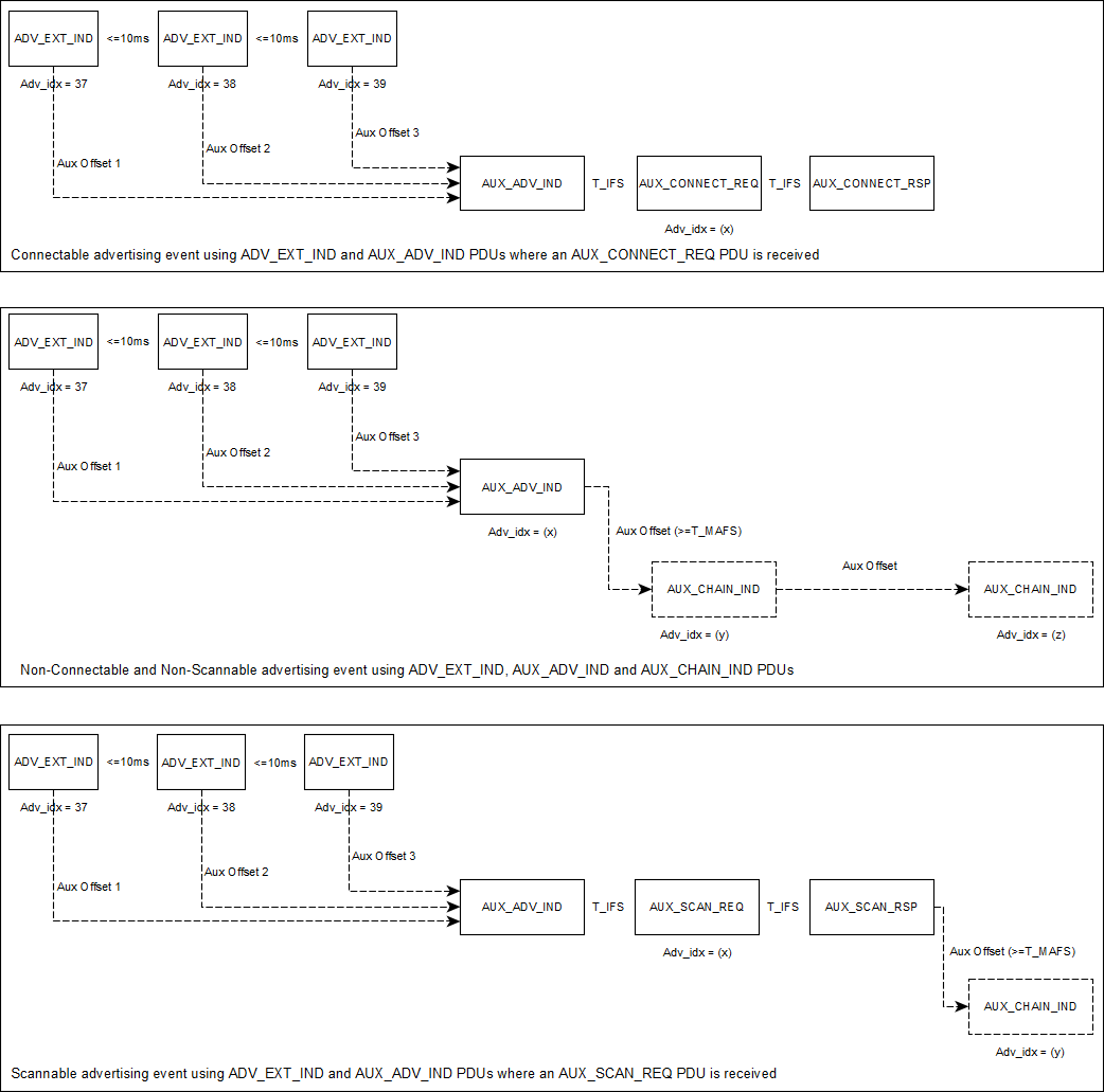
Figure 15 Examples of Extended Advertising Events
Table 28 describes the BLE functions related to the Extended Advertising operation.
Function |
Description |
|---|---|
ble_gap_supp_adv_sets_num_get() |
Get the number of supported advertising sets. |
ble_gap_max_adv_data_len_get() |
Get the maximum supported data length that can be used as advertisement data or scan response data. |
ble_gap_ext_adv_param_set() |
Set the extended advertising parameters for a specific advertising set. |
ble_gap_ext_adv_start() |
Start extended advertising on a specific advertising set. |
ble_gap_ext_adv_data_update() |
Update the advertising and scan response data for a specific advertising set. |
ble_gap_ext_adv_stop() |
Stop extended advertising on a specific advertising set. |
ble_gap_adv_set_remove() |
Remove a specific advertising set. |
Table 29 describes the BLE events related to the to the Extended Advertising operation
Event |
Description |
|---|---|
BLE_EVT_GAP_SCAN_REQ_RECEIVED |
Indicates that a scan request ( |
BLE_EVT_GAP_EXT_ADV_TERMINATED |
Indicates that extended advertising procedure has been completed. |
5.1.5. Periodic Advertising
Periodic advertising consists of advertisement PDUs (AUX_SYNC_IND) that are sent at a fixed interval.
This allows one or more scanners to synchronize with the advertiser so that the scanners and advertiser
would wake up at the same time, allowing the scanners to turn off their receiver when not needed.
The AUX_SYNC_IND PDUs can be combined with chained PDUs (AUX_CHAIN_IND)
allowing an even higher overall data throughput (up to 1650 bytes). Even though the periodic advertising
interval is fixed, the advertising data can change between those intervals.
To configure and enable periodic advertising (using ble_gap_periodic_adv_param_set(), ble_gap_periodic_adv_data_set()
and ble_gap_periodic_adv_enable()), one should first configure the specific advertising set for
Non-Connectable Non-Scannable extended advertising (using ble_gap_ext_adv_param_set()).
Note that even though enabling the periodic advertising (using ble_gap_periodic_adv_enable()) before the
extended advertising has been enabled (using ble_gap_ext_adv_start()) on the particular advertising set is possible,
the periodic advertisement will only start just after enabling the extended advertisement (using ble_gap_ext_adv_start()).
This means that to start periodic advertising, one should first start extended advertising.
After both the extended and periodic advertisements have been started, it is possible to stop the extended advertising
(using ble_gap_ext_adv_stop()) and let the periodic advertising go on alone. It is also possible to start the
extended advertisement again while the
periodic advertisement is enabled, if needed. Note that, althought the periodic advertising is autonomous and can remain enabled even
when the extended advertising is disabled, the only way for a scanner to get the timestamp, interval and PHY of a periodic advertising train
(AUX_SYNC_IND followed by zero or more AUX_CHAIN_IND PDUs) is by accessing the fields of the extended advertising PDUs (AUX_ADV_IND).
A common application scenario would be to enable both the extended and periodic advertising until one or more scanners get synchronized with the periodic advertising train. The advertiser could then disable the extended advertising and keep only the periodic advertising enabled to reserve power and bandwidth.
Periodic advertisements should be configured with a non-zero length of periodic advertising data.
These data are sent using AUX_SYNC_IND PDUs. If the data of the periodic advertisement do not fit
into a single PDU (or the controller decides to split them into more PDUs),
the AUX_SYNC_IND will be combined by AUX_CHAIN_IND PDUs.
A possible sequence of actions to enable periodic advertisement is shown below:
ble_gap_ext_adv_param_set()ble_gap_periodic_adv_param_set()ble_gap_periodic_adv_data_set()ble_gap_periodic_adv_enable()(Periodic advertising is kept disabled until
ble_gap_ext_adv_start()gets called)ble_gap_ext_adv_start()(Both Extended and Periodic advertising should be enabled at this point)
It is also possible to configure and enable the periodic advertisement after enabling the extended advertisement:
ble_gap_ext_adv_param_set()ble_gap_ext_adv_start()(Extended advertising should be enabled at this point)
ble_gap_periodic_adv_param_set()ble_gap_periodic_adv_data_set()ble_gap_periodic_adv_enable()(Both Extended and Periodic advertising should be enabled at this point)
Figure 16 depicts an example of periodic advertising. Note that the presense and number
of AUX_CHAIN_IND PDUs depends on the length of periodic advertising data and the scheduling taking place in the controller.
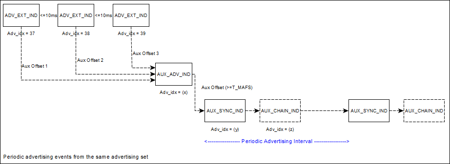
Figure 16 Example of Periodic Advertising Events
Table 30 describes the BLE functions related to the Periodic Advertising operation.
Function |
Description |
|---|---|
ble_gap_periodic_adv_param_set() |
Set the periodic advertising parameters of a specific advertising set. |
ble_gap_periodic_adv_data_set() |
Set the periodic advertising data of a specific advertising set. |
ble_gap_periodic_adv_enable() |
Disable periodic advertising on a specific advertising handle. |
ble_gap_periodic_adv_disable() |
Set the periodic advertising parameters of a specific advertising set. |
5.1.6. Extended Scanning
The BLE stack will enter the scanning state when ble_gap_ext_scan_start() is executed. When scanning, the controller listens
on the primary advertising physical channel for the types of PDUs and PHYs that are provided as parameters.
On receiving a PDU with an auxiliary pointer (AuxPtr field) present (ADV_EXT_IND`, AUX_SCAN_RSP, AUX_CHAIN_IND) , the scanner also
listens for the auxiliary PDU it points to (provided that the relevant PHY is supported) and will then attempt to receive it.
During scanning, the controller listens on a primary advertising channel index for the duration of the scan window (window field
of gap_ext_scan_phy_params_t). The scan interval (interval field of gap_ext_scan_phy_params_t) , is defined as the interval between the start of two
consecutive scan windows.
Extended advertising reports with the advertising or scan response data will be sent when the controller receives the relevant PDU types
(ADV_IND, ADV_DIRECT_IND, ADV_NONCONN_IND, ADV_SCAN_IND, ADV_SCAN_RSP, AUX_ADV_IND, AUX_SCAN_RSP, AUX_CHAIN_IND).
Note that the extended advertising reports that will be forwarded to the application (using BLE_EVT_GAP_EXT_ADV_REPORT events)
depend on the selected discovery mode (GAP_SCAN_GEN_DISC_MODE, GAP_SCAN_LIM_DISC_MODE, GAP_SCAN_OBSERVER_MODE).
The scan operation can be stopped either from the application code (using the ble_gap_ext_scan_stop() function), or autonomously by the BLE
stack Host (if GAP_SCAN_GEN_DISC_MODE or GAP_SCAN_LIM_DISC_MODE discovery modes are used), or by the BLE
stack Controller (depending on the values of duration and period fields of the gap_ext_scan_params_t structure). In
any case a BLE_EVT_GAP_EXT_SCAN_COMPLETED event will be received by the application with the relevant status code.
Table 31 describes the BLE functions related to the Extended Scanning operation.
Function |
Description |
|---|---|
ble_gap_ext_scan_start() |
Start extended scanning procedure. |
ble_gap_ext_scan_stop() |
Stop extended scanning procedure (initiated using ble_gap_ext_scan_start()). |
Table 32 describes the BLE events related to the to the extended scanning operation
Event |
Description |
|---|---|
BLE_EVT_GAP_EXT_ADV_REPORT |
Indicates that the controller has received an extended advertisment during active or passive scan. |
BLE_EVT_GAP_EXT_SCAN_COMPLETED |
Indicates that extended scanning procedure has been completed. |
5.1.7. Scanning and synchronizing to periodic advertisements
As described in the Periodic Advertising section, it is possible for an advertiser to broadcast periodic advertisements that
the scanners supporting the feature would be able to receive. To synchronize with a periodic advertiser, one should use the
ble_gap_periodic_adv_sync_create() function, providing as input parameters the SID (advertising set ID) and address of the remote advertiser.
When the synchronization is established (an event that will be signaled using BLE_EVT_GAP_PERIODIC_ADV_SYNC_ESTABLISHED) the scanner will
begin receiving periodic advertising packets (BLE_EVT_GAP_PERIODIC_ADV_REPORT events). Note that, even though the ble_gap_periodic_adv_sync_create()
function be called even when extended scanning is disabled (ble_gap_ext_scan_start() has not been called yet), synchronization
establishment can only occur when scanning is enabled. Once the synchronization has been established, the extended scanning operation
can be disabled without affecting the synchronization with the advertiser. Synchronization can be terminated later on using the
ble_gap_periodic_adv_sync_terminate() function. In case where the synchronization is lost unexpectedly the application will be notified using the BLE_EVT_GAP_PERIODIC_ADV_SYNC_LOST event.
The synchronization procedure normaly begins by initiating an extended scan procedure (using ble_gap_ext_scan_start()).
During the reception of extended advertiser
reports the scanner can discover any periodic advertisers in the same area by checking the periodic_adv_intv field of BLE_EVT_GAP_EXT_ADV_REPORT
events (which is non-zero when the respective advertiser has enabled periodic advertising). Extended advertiser reports also indicate
the address and SID used be the remote device, which should be provided as input parameters to ble_gap_periodic_adv_sync_create().
Table 33 describes the BLE functions related to the Periodic Scanning operation.
Function |
Description |
|---|---|
ble_gap_periodic_adv_list_size_get() |
Get the total number of Periodic Advertiser list entries that can be stored in the Controller. |
ble_gap_periodic_adv_sync_create() |
Synchronize with a periodic advertising train from an advertiser and begin receiving periodic advertising packets. |
ble_gap_periodic_adv_sync_cancel() |
Cancel an ongoing synchronization procedure (initiated using ble_gap_periodic_adv_sync_create()) while it is pending. |
ble_gap_periodic_adv_receive_options_set() |
Change the receive options of an established sync procedure (initiated using ble_gap_periodic_adv_sync_create()), identified by the sync_handle parameter. |
ble_gap_periodic_adv_sync_terminate() |
Terminate an established sync procedure (initiated using ble_gap_periodic_adv_sync_create()), identified by the sync_handle parameter. |
Table 34 describes the BLE events related to the to the periodic advertising synchronization operation
Event |
Description |
|---|---|
BLE_EVT_GAP_PERIODIC_ADV_SYNC_ESTABLISHED |
Indicates that the controller has received the first periodic advertising packet from an advertiser (When |
BLE_EVT_GAP_PERIODIC_ADV_REPORT |
Indicates that the controller has received a periodic advertisement |
BLE_EVT_GAP_PERIODIC_ADV_SYNC_LOST |
Indicates that the controller has not received a periodic advertisement from the remote advertiser within a timeout period |
5.1.8. Extended Connection
The BLE stack will enter the initiating state when ble_gap_ext_connect() is executed. When initiating, the controller listens
on the primary advertising physical channel on the PHYs that are provided as parameters.
During initiating, connection indications (CONNECT_IND PDU) are sent in response to a connectable advertisement in the primary advertising physical
channel (in case of ADV_IND and ADV_DIRECT_IND PDUs) while
connection requests (AUX_CONNECT_REQ PDU) are sent in response to a connectable advertisement in the secondary advertising physical
channel (in case of directed or undirected connectable AUX_ADV_IND PDUs). After sending the AUX_CONNECT_REQ PDU,
the controller waits for the advertiser to send an AUX_CONNECT_RSP PDU. Once an
AUX_CONNECT_RSP PDU is received, the controller exits the initiating state and transitions to the connection state.
The connection operation can be canceled (before a connection is been established) using the ble_gap_ext_connect_cancel() function.
It will be also stopped in case where a connection has been established. In any case
a BLE_EVT_GAP_EXT_CONNECTION_COMPLETED event will be received by the application with the relevant status code.
If the connection is established successfully, the application will also receive a BLE_EVT_GAP_CONNECTED event.
Table 35 describes the BLE functions related to the Extended Connection operation.
Function |
Description |
|---|---|
ble_gap_ext_connect() |
Connect to a device using the extended connection procedure. |
ble_gap_ext_connect_cancel() |
Cancel extended connection procedure (initiated using ble_gap_ext_connect()). |
Table 36 describes the BLE events related to the to the Extended Connection operation
Event |
Description |
|---|---|
BLE_EVT_GAP_EXT_CONNECTION_COMPLETED |
Indicates that extended connection procedure has been completed. |
5.1.8.1. Renesas BLE service API
The BLE service API header files are in
<SDK_ROOT_PATH>/sdk/interfaces/ble/services/include.
The services-specific API, callback function prototypes and definitions are included in each service’s header file. The services implemented are the following:
Header file |
Description |
|---|---|
bas.h |
Battery Service |
bcs.h |
Body Composition Service |
ble_service.h |
Services handling routines API |
bls.h |
Blood Pressure Service |
bms.h |
Bond Management Service |
cts.h |
Current Time Service |
dis.h |
Device Information Service |
dlg_debug.h |
Renesas Debug Service |
dlg_suota.h |
Renesas SUOTA Service |
hids.h |
Human Interface Device Service |
hrs.h |
Heart Rate Service |
ias.h |
Immediate Alert Service |
lls.h |
Link Loss Service |
scps.h |
Scan Parameter Service |
sps.h |
Serial Port Service |
svc_defines.h |
Common definitions for all services |
svc_types.h |
Common characteristic common |
tps.h |
Tx Power Service |
uds.h |
User Data Service |
wss.h |
Weight Scale Service |
All services have an initialization function defined. This function is called with arguments that vary for different services.
The most common argument is a pointer to one or more callback functions that should be called upon a service-specific event. For example, the prototype for the initialization function of the Immediate Alert Service (ias.h) is the following:
ble_service_t *ias_init(ias_alert_level_cb_t alert_level_cb)
Function ias_init() has only one argument. It is a pointer to the callback function that will be called when a peer device has modified the value of the Immediate Alert Level characteristic. This callback function is part of the user application code and should provide the application handling required for the change to the Immediate Alert Level.
The return value from all initialization functions is the created service’s handle which is used to reference the service in the application. To understand how the service interacts with the BLE Framework it is useful to know what this handle represents. The handle is a pointer to a generic structure (ble_service_t) that defines how the service should interact with the framework. Within each service there is an internal service definition (XXX_service_t) as shown in Figure 17. This contains the generic service structure plus a set of handles, one for each GATT characteristic that the service implements. This XXX_service_t structure is populated by XXX_init() for that service. The start_h and end_h handles will contain the start and end handles of the attributes for this service within the overall GATT table provided by the GATT server. So, when a GATT client requests a Service Discovery from the server these represent the start and end handles that the client would use to access service XXX.

Figure 17 Structure of a service handle
The set of optional callbacks allow each service to specify if it wants to do some specific handling on a certain event received by the BLE Framework. If the service wants to be informed when another BLE device has connected to this device then it can define its own handle_connected_evt() function and plug it into the connected_evt callback. Each service declares its handle_connected_evt() function as static in xxx.c and by convention in the SDK they all share the same function names in each service.
As each service is initialized and thus added to the BLE services framework with ble_service_add(), its generic services structure is added to a structure of supported services as shown in Figure 18.

Figure 18 Structure of supported services
Now that the main internal services structure has been explained, it is easier to follow how the service initialization defines how the service operates.
Within the BLE service framework, the main event handler is ble_service_handle_event() which is shown below.
bool ble_service_handle_event(const ble_evt_hdr_t *evt)
{
     switch (evt->evt_code) {
     case BLE_EVT_GAP_CONNECTED:
             connected_evt((const ble_evt_gap_connected_t *) evt);
             return false; // make it "not handled" so app can handle
     case BLE_EVT_GAP_DISCONNECTED:
             disconnected_evt((const ble_evt_gap_disconnected_t *) evt);
             return false; // make it "not handled" so app can handle
     case BLE_EVT_GATTS_READ_REQ:
             return read_req((const ble_evt_gatts_read_req_t *) evt);
     case BLE_EVT_GATTS_WRITE_REQ:
             return write_req((const ble_evt_gatts_write_req_t *) evt);
     case BLE_EVT_GATTS_PREPARE_WRITE_REQ:
             return prepare_write_req((const ble_evt_gatts_prepare_write_req_t *) evt);
     case BLE_EVT_GATTS_EVENT_SENT:
             return event_sent((const ble_evt_gatts_event_sent_t *) evt);
     }

     return false;
}
Each of these sub-handlers inside ble_service_handle_event() search throughout the added services to find one that has defined a behavior for this event. There are two types of events that are handled differently.
5.1.8.2. Connection Orientated Events
The connection and disconnection events are potentially of interest to all registered services, so all services can be informed. The cleanup on shutdown is handled in the same way.
For example a connection event will call the BLE service’s statically defined connected_evt() function (sdk/interfaces/ble/services/src/ble_service.c). This will go through all the services registered to the BLE service framework to check for services that have registered to connection events during the service initialization. For each such service the connected_evt callback will be called.
5.1.8.3. Attribute Orientated Events
These are events that have to do with a given attribute handle. As each attribute is related to a unique service the first step in each of these handlers is to identify which service the attribute belongs to.
For example a write request on a specific attribute will call the BLE service’s statically defined write_req() function (sdk/interfaces/ble/services/src/ble_service.c) as shown below. This will first identify which service owns that attribute with find_service_by_handle(). Then if it has a write_req callback defined it executes the callback.
static bool write_req(const ble_evt_gatts_write_req_t *evt)
{
        ble_service_t *svc = find_service_by_handle(evt->handle);

        if (!svc) {
                return false;
        }

        if (svc->write_req) {
                svc->write_req(svc, evt);
        }

        return true;
}
An example of this flow is the Write No Response procedure that can be applied to the Immediate Alert Level characteristic of the Immediate Alert Service. When a GATT client requests a write to that characteristic it will trigger the write_req() sub-handler under ble_service_handle_event().
The write_req() sub-handler will use find_service_by_handle() to see if any of the added services are registered for that characteristic. It will match it with the Immediate Alert Service (IAS) and as the IAS has registered a Write Request handler the IAS handle_write_req() will be called (sdk/interfaces/ble/services/src/ias.c).
static void handle_write_req(ble_service_t *svc, const ble_evt_gatts_write_req_t *evt)
{
        ia_service_t *ias = (ia_service_t *) svc;
        att_error_t err = ATT_ERROR_OK;

        if (evt->length == 1) {
                uint8_t level;

                /*
                * This is write-only characteristic so we don't need to store value written
                * anywhere, can just handle it here and reply.
                */

                level = get_u8(evt->value);

                if (level > 2) {
                        err = ATT_ERROR_APPLICATION_ERROR;
                } else if (ias->cb) {
                        ias->cb(evt->conn_idx, level);
                }
        }

        ble_gatts_write_cfm(evt->conn_idx, evt->handle, err);
}
By calling ias->cb() function, this handler actually calls the application supplied callback function passed as an argument when ias_init() was called by the application. Finally, it sends a Write Confirmation to update the value at the attribute database maintained in the BLE Stack.
This is only an example of the way the BLE service framework translates BLE events to BLE service events. Different events in different services can have different levels of complexity, but most of the times this complexity is contained within the BLE service API. The aim is that the application only needs to call the service’s initialization function and define the appropriate callback functions to handle all service’s events.
In addition, some services define additional service-specific API calls. For instance, the Heart Rate Service implementation defines an API to trigger notifications of the Heart Rate Measurement characteristic, using functions hrs_notify_measurement() and hrs_notify_measurement_all() (the first is used to notify the characteristic to a specified peer, while the second is used to notify the characteristic to all subscribed peers). Some services also define some internal helper functions that are used to manipulate characteristic values, and some services require attribute initial values as arguments of the initialization function.
The BLE service API adds another layer to the general BLE API. Together the BLE adapter, BLE manager, BLE API library and BLE service framework results in the BLE Framework.
The BLE services API provides an off the shelf solution to implement an application using many of the common adopted BLE services. The underlying BLE API and GATT server API can be used to create other adopted services or even custom services using the BLE services as a template.
The following sections will provide an overview of a generic application and then will describe in detail several of the example BLE projects included in the DA1459x SDK:
ble_peripheral |
A project that can be used as a template for developing BLE peripheral applications. The project includes some of the services implemented under the BLE service framework. |
ble_suota_client |
This application is a SUOTA 1.2 client implementation and allows to update SUOTA-enabled devices over the air, using a simple serial console interface. |
ams |
Apple Media Service demo application |
ancs |
This application is a sample implementation for Apple Notification Center Service (ANCS) client. It supports all the features of the Notification Consumer (NC) role provided by this service. |
blp_sensor |
This application is a sample implementation of the Blood Pressure Sensor as defined in the Blood Pressure Profile Specification. |
bms |
This application is an implementation of the Bond Management Service, as defined by the Bluetooth Special Interest Group. |
cscp_collector |
This application is a sample implementation of Cycling Speed And Cadence collector as defined by CSCP specification 1.0. All features are supported (i.e. both mandatory and optional features). |
hogp_device |
This application is a sample implementation of a HOGP Device. |
hogp_host |
This application is a sample implementation of the HOGP Host of the HID Over GATT Profile, as defined by the Bluetooth Special Interest Group. |
hrp_collector |
This application is a sample implementation of Heart Rate collector as defined by HRP specification 1.0. All features are supported (i.e. both mandatory and optional features). |
hrp_sensor |
This application is a sample implementation of a Heart Rate Sensor of the Heart Rate Profile, as defined by the Bluetooth Special Interest Group. |
wsp_weightscale |
This application is a sample implementation of Weight Scale role of the Weight Scale Profile specification, as defined by the Bluetooth Special Interest Group. |
ble_cli |
This application provides a Command Line Interface handling functions and events from the SDK APIs. |
ble_external_host |
The application purpose is the use of transport layer on DA1459x platform by an external user. For example a different BLE Host stack may be used with BLE Controller on DA146xx targets. |
ble_multi_link |
This application allows connecting to many devices by writing their addresses to characteristic. |
pxp_reporter |
This application is a sample implementation of Proximity Reporter of the Proximity Profile, as defined by the Bluetooth Special Interest Group. |
ble_central |
This application is an example of BLE central role device implementation. It connects to a remote device, searches for services, characteristic and descriptors. |
ble_adv |
This application is an example of BLE featured demo. It implements the peripheral role of device, advertising information about its accessibility. |
5.1.8.4. Configuring the project
In each project the BLE Framework and BSP are configured via a set of custom config files that set the defines and macros used in that project. These files are found in the config directory of each project.
In the case of the pxp_reporter project the files are config/custom_config_eflash.h and config/custom_config_qspi.h (for eFLASH and QSPI build configuration respectively).
Note
Currently pxp_reporter is the only application provided by SDK with QSPI build configuration. Nevertheless, users have the capability to integrate this option into any other application.
Any definitions set in these file will override the default SDK values which are found in the following files:
sdk/bsp/config/bsp_defaults.h
sdk/bsp/config/bsp_defaults_da1459x.h
sdk/bsp/config/bsp_memory_defaults.h
sdk/middleware/config/middleware_defaults.h
sdk/interfaces/ble/config/ble_config.h
sdk/free_rtos/include/FreeRTOSConfig.h
5.1.8.5. BLE application structure
All the BLE application projects in the DA1459x SDK have a similar structure. This involves several FreeRTOS tasks at different priority levels to ensure that the overall system’s real time requirements are met.
The BLE application is implemented in a FreeRTOS task that is created by the system_init() function. system_init() runs at the highest priority at startup and is also responsible for starting the BLE manager and BLE adapter tasks.
The application task has the following flow:
Device initialization and configuration: Start-up BLE, setting device role, device name, appearance and other device parameters.
Attribute database creation (GATT server devices): Creation of services and attributes using the BLE service framework. This must be done after (1) to prevent deletion of the attribute database.
Air operation configuration and initiation: BLE peripheral devices usually end-up advertising and BLE central devices end-up scanning and/or attempting to connect to another device.
The infinite
for(;;)loop, which is the application’s event handling loop. The application has been set-up as desired and now it is waiting for BLE events to respond to, like connections or write requests.The BLE adapter (
ad_ble_task) must have a higher priority than the application task(s) because it runs the BLE Host stack scheduler and it handles time critical tasks.Most of the BLE applications use the FreeRTOS task notifications mechanism to block.
ble_adv_demois the simplest application and is the only project that does not use this mechanism. Instead, it just blocks on the BLE manager’s event queue.In addition to the BLE-related functionality most projects also use other system modules, like software timers or sensors. In this case, the application usually defines callback functions to be triggered on these system events or interrupts. These callback functions should use task notifications to unblock the application task which can then handle the event or interrupt in the application task’s context (under its
for(;;)loop).
Warning
Calling a BLE API function inside a callback function triggered on a timer expiry will execute the BLE API function in the timer’s task context. Calling other functions in the callback functions can also have implications on real time performance or in corrupting the small stack used by the timer task.
5.1.9. BLE Security
The Bluetooth specification defines the security options for device authentication and link encryption. These aspects of security are handled seamlessly by the BLE Framework. The API in Table 39 is able to set-up security, initiate pairing, do a security request or set-up encryption using previously exchanged keys. Most details of the procedures will be handled internally by the BLE Framework and the application will be notified only if intervention is needed or when the procedure is completed. These options will be described in detail in Section 5.1.9.2 and Section 5.1.10.
The generation and storage of the security keys and other bonding information is also handled by the BLE Framework. Persistent storage can also be used to enable storage of the security keys and bonding data info in the flash. The BLE Framework can then retrieve this information after a power cycle and use it to restore connections with previously bonded devices. This is described in Section 5.1.12.
5.1.9.1. LE Secure
LE Secure Connections pairing is supported and enabled by default by the SDK using the API described in Section 5.1.9.2, LE Secure Connections pairing will be used if the connected peer supports the feature without the need for the application to specifically request it. If the combination of the devices’ capabilities result in a numeric comparison pairing algorithm (introduced and used for the LE Secure Connections pairing), the application will be notified of a numeric comparison request during pairing by the reception of a BLE_EVT_GAP_NUMERIC_REQUEST event and should respond using ble_gap_numeric_reply() function.
If the application needs to use only LE Legacy Pairing and disable LE Secure Connections support in the SDK, it should define dg_configBLE_SECURE_CONNECTIONS macro to 0 in the application config file.
5.1.9.2. Functions
Table 39 summarizes the API functions that can be used by the application to set-up security features.
API call |
Description |
|---|---|
ble_gap_pair() |
Initiate a pairing or bonding procedure with a connected peer. Depending on whether the device is master or slave on the connection, this call will result either in a pairing or a security request respectively. |
ble_gap_pair_reply() |
Reply to a received |
ble_gap_passkey_reply() |
Reply to a received |
ble_gap_numeric_reply() |
Reply to a received |
ble_gap_set_sec_level() |
Set the security level for a connection. If the device is already bonded, the existing Long Term Key (LTK) will be used to set-up encryption. If the device is not bonded, a pairing or a security request will be triggered (depending on whether the device is master or slave on the connection) with the bond flag set to false. |
ble_gap_get_sec_level() |
Get the security level currently established on a connection. |
ble_gap_unpair() |
Unpair a previously paired or bonded device. This will also remove security keys and bonding data info currently present in BLE storage. |
5.1.9.3. Events
Table 40 describes the BLE events related to security that may be received by the application and the proper API functions to respond to them.
Event |
Argument |
Description |
|---|---|---|
BLE_EVT_GAP_PAIR_REQ |
ble_evt_gap_pair_req_t |
Pairing request received by a connected peer. Member |
BLE_EVT_GAP_PAIR_COMPLETED |
ble_evt_gap_pair_completed_t |
A previously requested pairing procedure has been completed. Member |
BLE_EVT_GAP_SECURITY_REQUEST |
ble_evt_gap_security_request_t |
Security request received by a connected peripheral peer. Members |
BLE_EVT_GAP_PASSKEY_NOTIFY |
ble_evt_gap_passkey_notify_t |
A passkey has been generated during a pairing procedure. This event will be received if the application has display capability. Member |
BLE_EVT_GAP_PASSKEY_REQUEST |
ble_evt_gap_passkey_request_t |
A passkey has been requested during a pairing procedure. This event will be received if the application has keyboard capability. The application should use |
BLE_EVT_GAP_NUMERIC_REQUEST |
ble_evt_gap_numeric_request_t |
A numeric comparison has been requested during a pairing procedure. This event will be received if the application has keyboard or Yes/No and display capability. The application should use |
BLE_EVT_GAP_SEC_LEVEL_CHANGED |
ble_evt_gap_sec_level_changed_t |
The security level has been changed on an established link. Member |
BLE_EVT_GAP_SET_SEC_LEVEL_FAILED |
ble_evt_gap_set_sec_level_failed_t |
Setting the security level on an established link using |
5.1.9.4. Macros
Table 41 contains the configuration macros related to BLE security.
Macro |
Default |
Description |
|---|---|---|
dg_configBLE_SECURE_CONNECTIONS |
1 |
Set to 1 to use LE Secure Connections pairing if the peer supports the feature or to 0 to always use LE Legacy Pairing. |
dg_configBLE_PAIR_INIT_KEY_DIST |
GAP_KDIST_ENCKEY | GAP_KDIST_IDKEY | GAP_KDIST_SIGNKEY |
Set the security keys requested to be distributed by the pairing initiator during a pairing feature exchange procedure. |
dg_configBLE_PAIR_RESP_KEY_DIST |
GAP_KDIST_ENCKEY | GAP_KDIST_IDKEY | GAP_KDIST_SIGNKEY |
Set the security keys requested to be distributed by the pairing responder during a pairing feature exchange procedure. |
5.1.10. Message Sequence Charts (MSCs)
5.1.10.1. Central
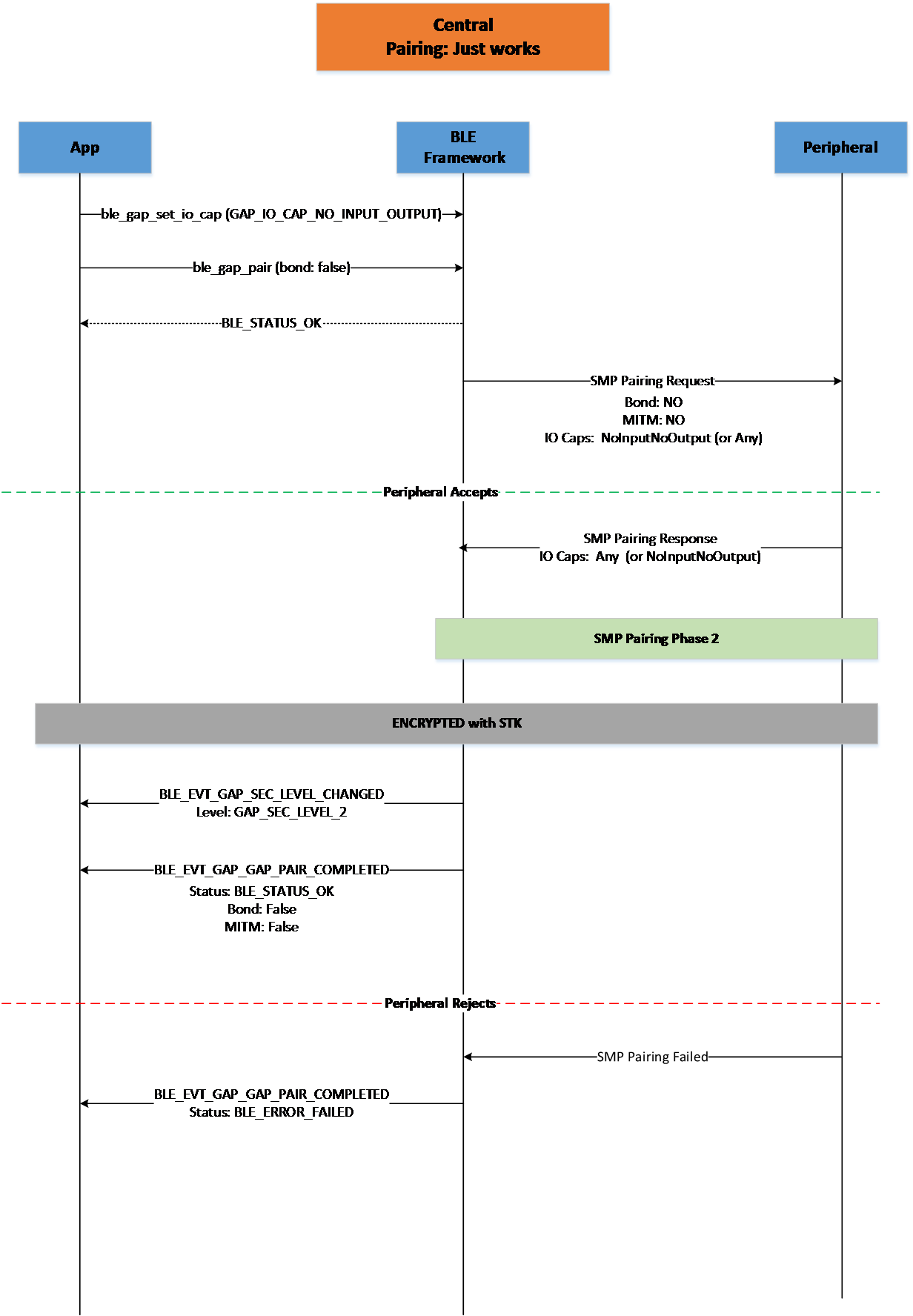
Figure 19 Central Pairing Just Works
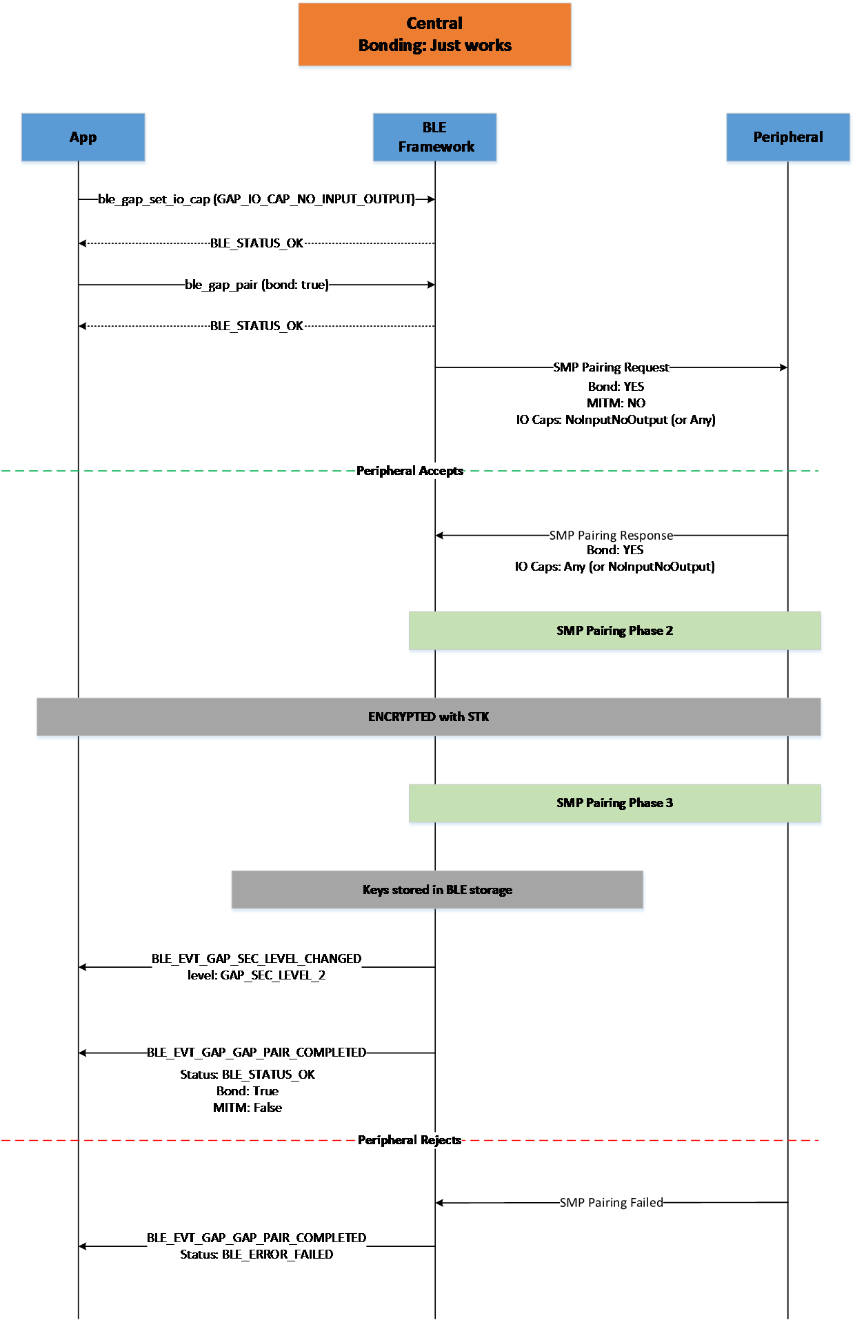
Figure 20 Central Bonding Just Works

Figure 21 Central Bonding Passkey Entry (Central Display)
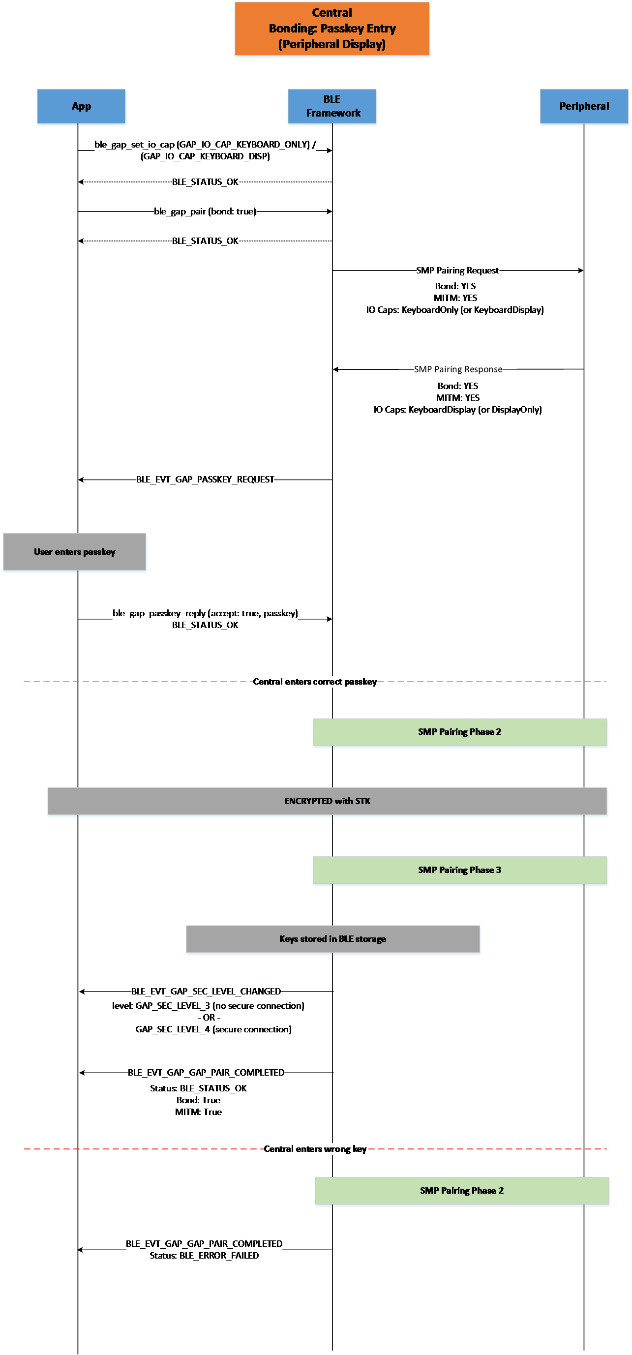
Figure 22 Central Bonding Passkey Entry (Peripheral Display)
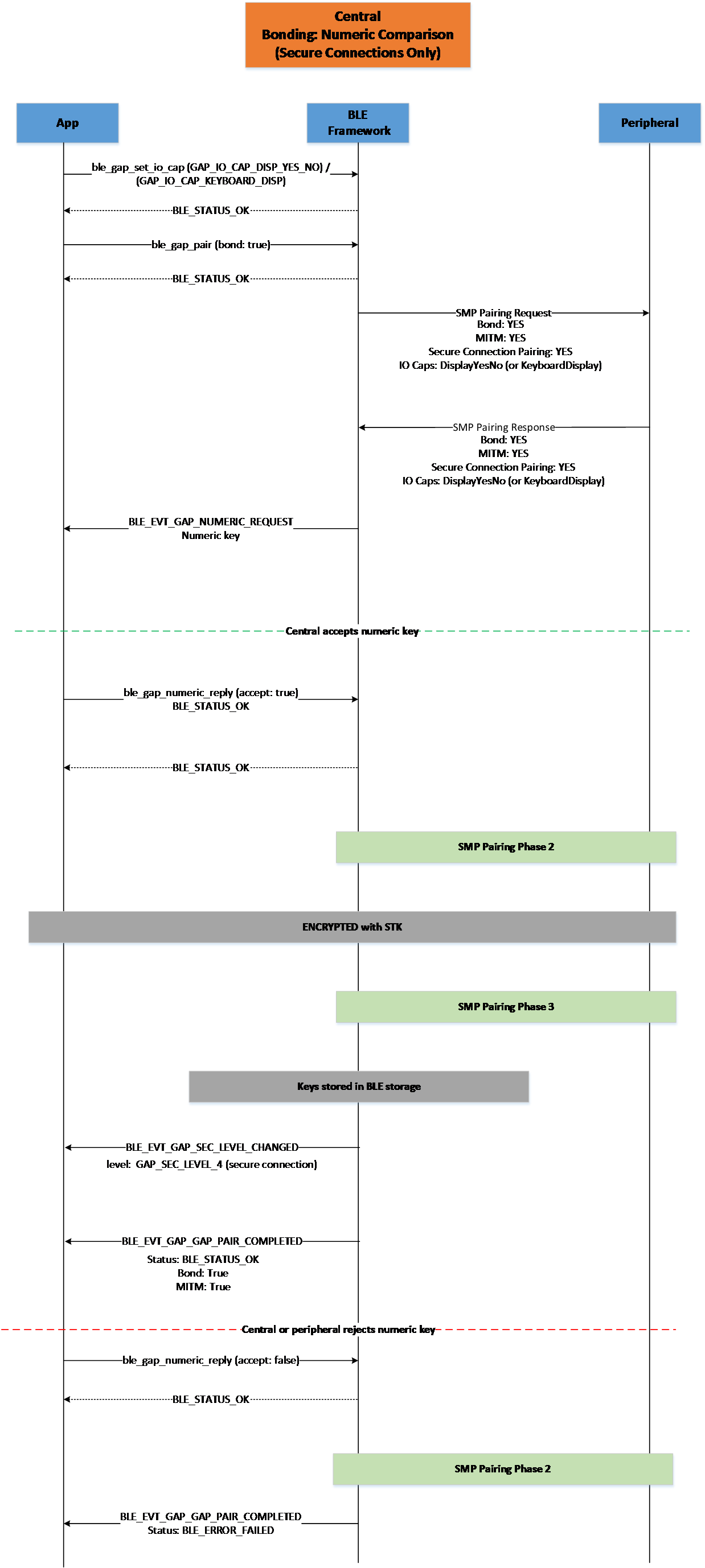
Figure 23 Central Bonding Numeric Comparison (Secure Connections Only)
5.1.10.2. Peripheral
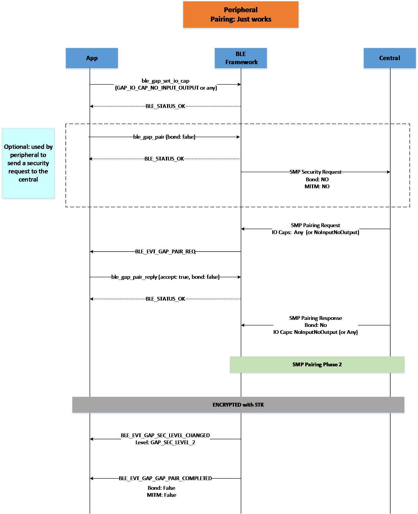
Figure 24 Peripheral Pairing Just Works
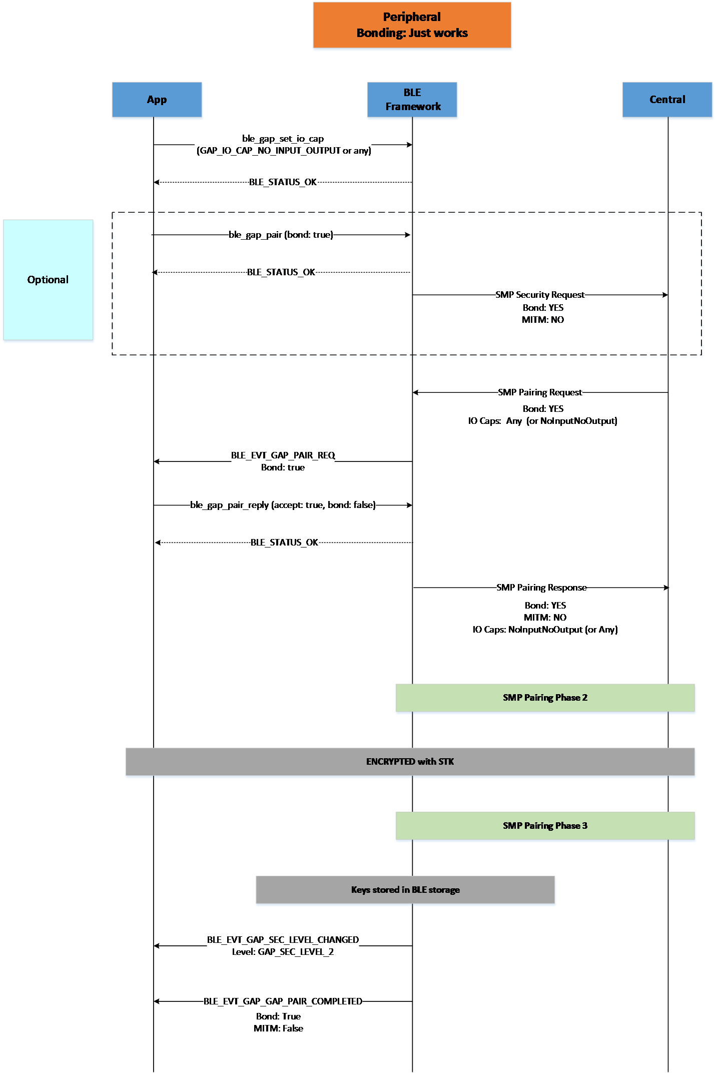
Figure 25 Peripheral Bonding Just Works
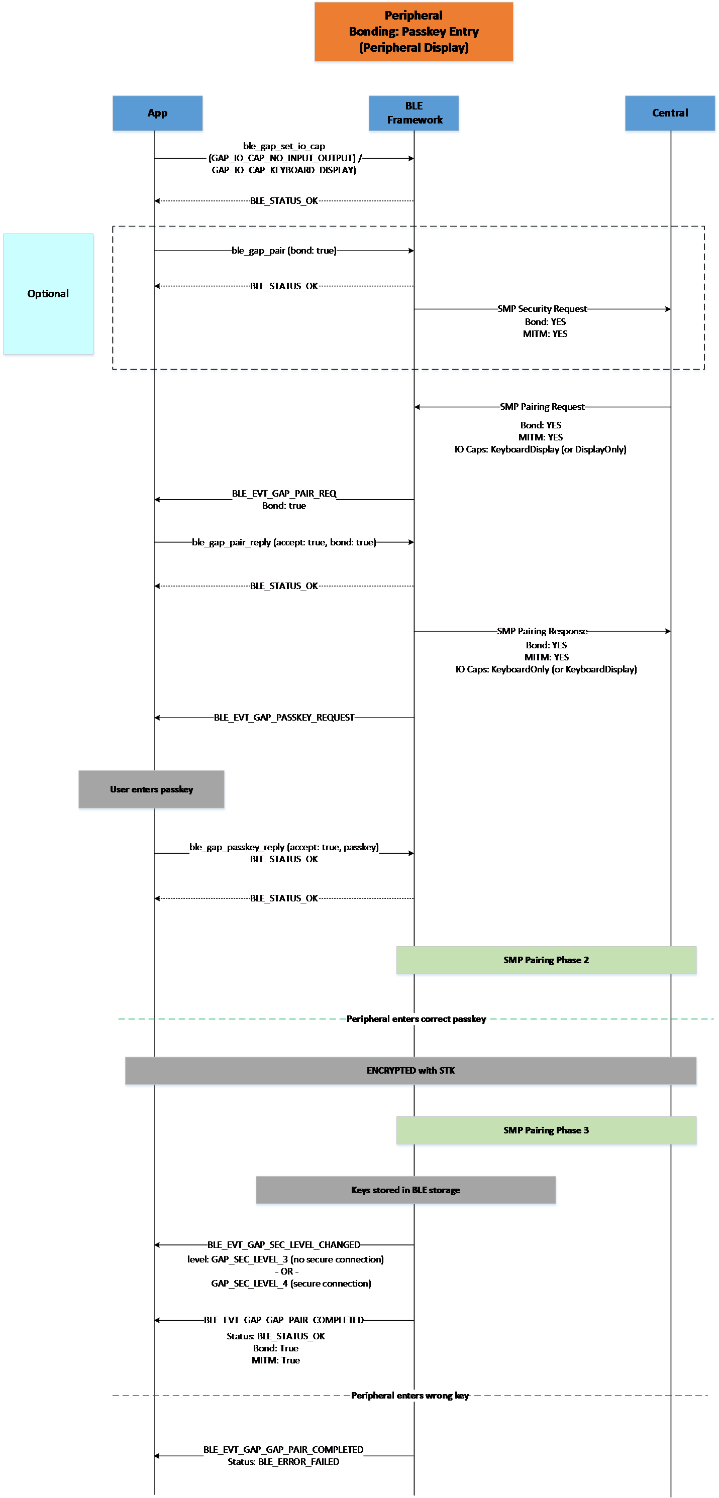
Figure 26 Peripheral Bonding Passkey Entry (Peripheral Display)
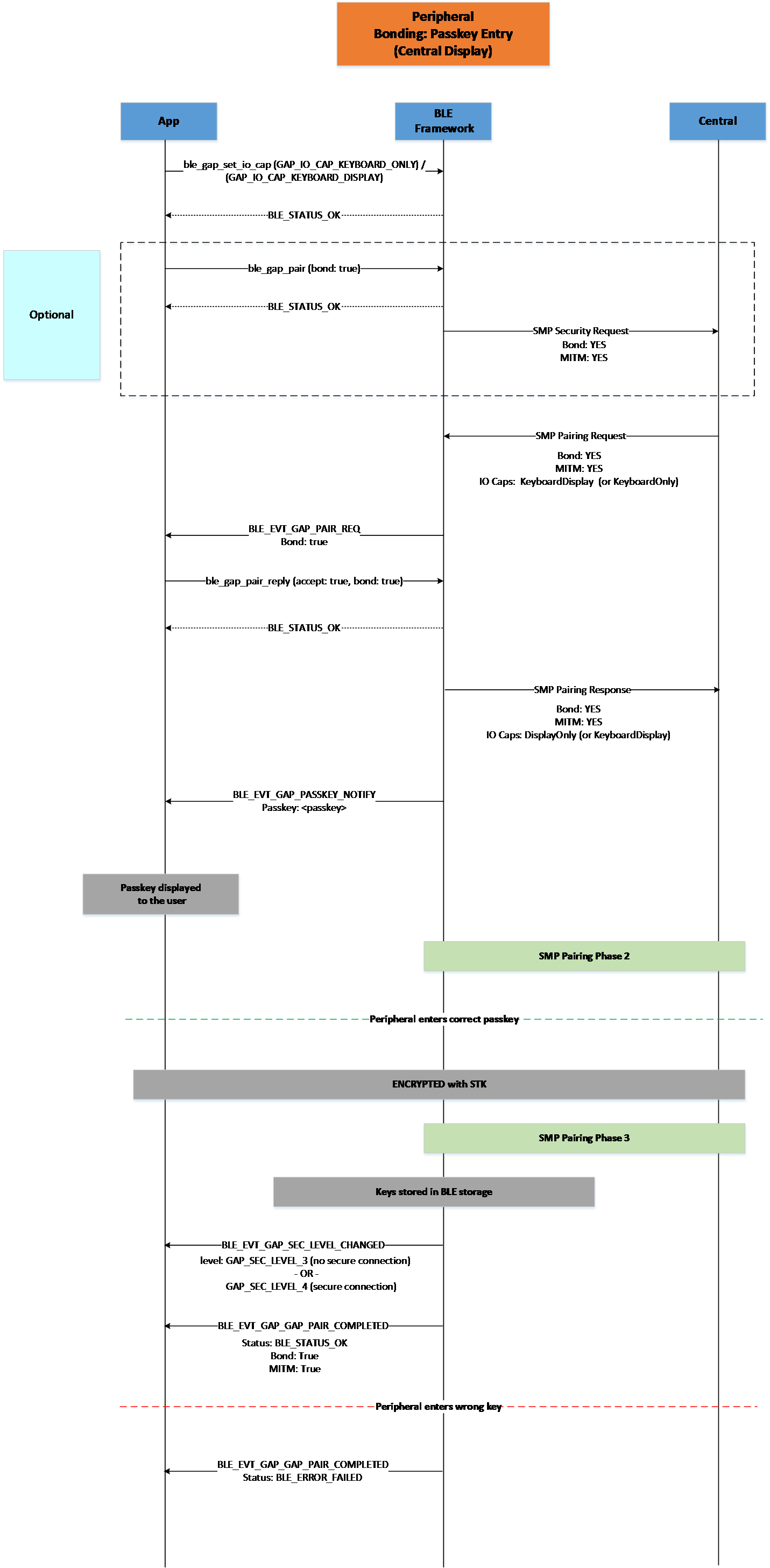
Figure 27 Peripheral Bonding Passkey Entry (Central Display)
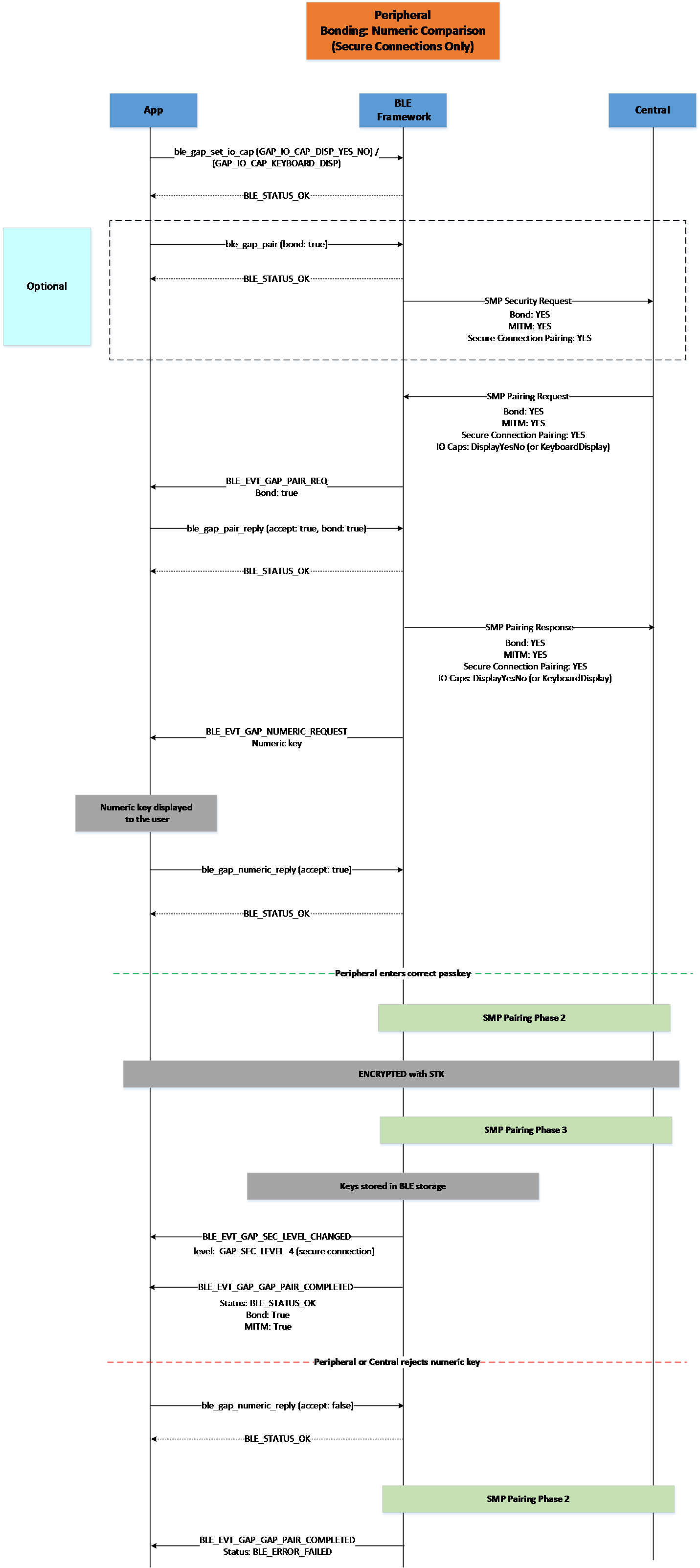
Figure 28 Peripheral Bonding Numeric Comparison (Secure Connections Only)
5.1.11. BLE Power Control
The Bluetooth specification defines the way by which a device can request a remote device to make a specified change in its TX power level on a given PHY. The response of the peer device contains a value that indicates an acceptable reduction in the power level that allows the local device to further reduce its transmit power level to the minimum level possible. The local and remote devices can also share their current transmit power levels. This way they can also calculate the link path loss between them.
This 5.2 BLE Feature is supported and enabled by default by the SDK using the API described in Section 5.1.11.2
5.1.11.1. RSSI Golden Range
Note
The RSSI Golden Range is only applicable to the DA14594 SOC.
The BLE specification defines that the radio receiver can have an RSSI Golden Range that it prefers the incoming signal to remain within. This functionality is supported and so the local controller adjusts automatically the peer’s TX power to bring RSSI to its preferred value inside this Golden Range.
The local device continuously monitors the RSSI and if it is below the minimum or above maximum acceptable values of the RSSI
it uses the Power Control Request procedure to request an increase or decrease the TX power level of the peer device. This procedure is done automatically by the local device. The application
can be informed about the changes in the local and the remote TX power levels by using the ble_gap_tx_power_report_en() command. The changes in the TX power level are then reported to the application by the
BLE_EVT_GAP_TX_PWR_REPORT event.
The default values of the RSSI Golden Range can be seen in Table 44.
5.1.11.2. Functions
Table 42 summarizes the API functions that can be used by the application to use the LE Power Control feature.
API call |
Description |
|---|---|
ble_gap_local_tx_power_get() |
Get the current and maximum transmit power levels of the local device, on the ACL connection, for the indicated PHY. |
ble_gap_remote_tx_power_get() |
Get the TX power level used by the remote device, on the ACL connection for the indicated PHY. |
ble_gap_path_loss_report_params_set() |
Set the path loss threshold reporting parameters |
ble_gap_path_loss_report_en() |
Enable or disable path loss reporting. |
ble_gap_tx_power_report_en() |
Enable or disable reporting of TX power level in the local and remote device for the ACL connection. |
ble_gap_rf_path_compensation_set() |
Indicate the RF path gain or loss between the RF transceiver and the antenna contributed by intermediate components. |
5.1.11.3. Events
Table 43 describes the BLE events related to LE Power Control that may be received by the application.
Event |
Argument |
Description |
|---|---|---|
BLE_EVT_GAP_LOCAL_TX_PWR |
ble_evt_gap_local_tx_pwr_t |
Reading of the local transmit power has been completed. Member |
BLE_EVT_GAP_TX_PWR_REPORT |
ble_evt_gap_tx_pwr_report_t |
Reports that the local or remote transmit power has changed or that a |
BLE_EVT_GAP_PATH_LOSS_THRES |
ble_evt_gap_path_loss_thres_t |
Reports a path loss threshold crossing. Member |
5.1.11.4. Macros
Table 44 contains the configuration macros related to BLE Power Control.
Macro |
Default |
Description |
|---|---|---|
dg_configBLE_GOLDEN_RANGE_LOW |
-70 |
Sets the lower RSSI value (dBm) of the Golden Range. |
dg_configBLE_GOLDEN_RANGE_UP |
-40 |
Sets the upper RSSI value (dBm) of the Golden Range. |
dg_configBLE_GOLDEN_RANGE_PREF |
-55 |
Sets the preferred RSSI value (dBm) inside the Golden Range (dBm). |
dg_configBLE_PCLE_MIN_TX_PWR_IDX |
GAP_TX_POWER_MINUS_26_dBm |
Sets the Minimum TX Power index used in LE Power Control (dBm). The available TX power levels can be seen in Table 45 |
dg_configBLE_PCLE_MAX_TX_PWR_IDX |
GAP_TX_POWER_MAX |
Sets the Maximum TX Power index used in LE Power Control (dBm). The available TX power levels can be seen in Table 45 |
5.1.11.5. Supported TX Power Levels
Table 45 lists the available TX power levels. The corresponding gap_tx_power_t enumeration is located in the sdk/ble/api/include/ble_gap.h.
Tx Power level |
Corresponding index |
|---|---|
GAP_TX_POWER_MAX |
17 |
GAP_TX_POWER_6_dBm |
17 |
GAP_TX_POWER_5_dBm |
16 |
GAP_TX_POWER_4_5_dBm |
15 |
GAP_TX_POWER_4_dBm |
14 |
GAP_TX_POWER_3_dBm |
13 |
GAP_TX_POWER_2_dBm |
12 |
GAP_TX_POWER_1_5_dBm |
11 |
GAP_TX_POWER_0_dBm |
10 |
GAP_TX_POWER_MINUS_1_dBm |
9 |
GAP_TX_POWER_MINUS_2_dBm |
8 |
GAP_TX_POWER_MINUS_3_dBm |
7 |
GAP_TX_POWER_MINUS_6_dBm |
6 |
GAP_TX_POWER_MINUS_8_dBm |
5 |
GAP_TX_POWER_MINUS_12_dBm |
4 |
GAP_TX_POWER_MINUS_18_dBm |
3 |
GAP_TX_POWER_MINUS_22_dBm |
2 |
GAP_TX_POWER_MINUS_26_dBm |
1 |
GAP_TX_POWER_MINUS_50_dBm |
0 |
GAP_TX_POWER_MIN |
0 |
Note
In case of LP Radio mode, selecting power higher than the max possible by the HW in this mode, has no effect.
5.1.12. BLE Storage
BLE Storage is the module that implements storage functionality for information related to connected and bonded peers, like security keys, CCC descriptors configuration and application-defined values. BLE Storage can maintain the list of connected and bonded devices both in RAM and in persistent storage (for example, in the flash). By default, devices are managed in RAM only and persistent storage must be explicitly enabled in the application’s configuration by defining macro CONFIG_BLE_STORAGE. Device data is then stored using Non-Volatile Memory Storage (NVMS) on the generic partition (see Section 4.2 for details).
Two kinds of data are stored:
Device pairing data (exchanged keys and related information).
Application-defined data managed using the BLE storage API (only the values with the ‘persistent’ flag set are stored in flash, for example CCC descriptor values).
Persistent storage can be enabled by the application by adding the following entries in the application’s custom configuration file:
// enable BLE persistent storage
#define CONFIG_BLE_STORAGE

// enable Flash and NVMS adapters with VES (required by BLE persistent storage)
#define dg_configFLASH_ADAPTER                  1
#define dg_configNVMS_ADAPTER                   1
#define dg_configNVMS_VES                       1
The maximum number of bonded devices can be set using the defaultBLE_MAX_BONDED macro (defined to 8 by default). If the application attempts to bond more devices than its allowed, an error will be returned. This error should be handled by the application. It can then either unpair one of the currently bonded devices (using ble_gap_unpair() API function) or perform pairing without bonding.
Technical details on the BLE Storage implementation can be found in the following readme file:
<SDK_ROOT_PATH>/sdk/interfaces/ble/README.md
5.1.12.1. Device Unique Symmetric Key (DUSK) Support
To enhance secure storage and comply with the Radio Equipment Directive (RED), SDK10 introduces support for generating and storing a Device Unique Symmetric Key (DUSK). This per-device random key is generated using the TRNG hardware accelerator and stored securely in a designated OTP memory slot. It is used by the secure store functionality to:
Encrypt bonding data managed by the BLE Manager and stored in the embedded flash
Allow applications to securely store and access encrypted user data
The DUSK is written to OTP via a new generate_dusk command added to the programming tools (cli_programmer, libprogrammer, uartboot). This approach ensures the key is never exposed in SRAM and persists across power cycles.
To avoid overwriting the DUSK slot, the generate_keys.py under utilities/python_scripts/secure_image script has been updated to prompt users before generating the 8th symmetric user key.
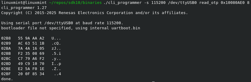
Figure 29 How to read DUSK
./cli_programmer -s 115200 /dev/ttyUSB0 read_otp 0x10080AE0  8

./cli_programmer gdbserver read_otp 0x10080AE0  8
To support the DUSK feature, the generate_keys.py script has been updated. This script typically generates eight 256-bit symmetric user keys for image signature verification and decryption, storing them in the OTP’s User Data Encryption Keys – Payload section.
Since the last slot is now reserved for the Device Unique Symmetric Key (DUSK), the script has been modified to prompt the user to optionally skip generating the eighth key. This prevents accidental overwriting of the DUSK slot during key provisioning.
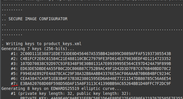
Figure 30 Modification of generate_keys.py
5.1.13. Logical Link Control and Adaptation Layer Protocol
The Logical Link Control and Adaptation Layer Protocol, referred to as L2CAP provides connection-oriented and connectionless data services to upper layer protocols with protocol multiplexing capability and segmentation and reassembly operation. As referred in [Ref_02], L2CAP permits higher level protocols and applications to transmit and receive upper layer data packets (L2CAP Service Data Units, SDU) up to 64 kilobytes in length. L2CAP also permits per-channel flow control and retransmission.
The L2CAP layer provides logical channels, named L2CAP channels, which are multiplexed over one or more logical links. Each one of the endpoints of an L2CAP channel is referred to by a channel identifier (CID).
L2CAP channels may operate in one of five different modes as selected for each L2CAP channel. The modes are:
Basic L2CAP Mode (equivalent to L2CAP specification in Bluetooth v1.1)
Flow Control Mode
Retransmission Mode
Enhanced Retransmission Mode
Streaming Mode
LE Credit Based Flow Control Mode
The null CID (0x0000) is never used as destination endpoint. Identifiers
from 0x0001 to 0x003F are reserved for specific L2CAP functions. These
channels are referred to as Fixed Channels.
CID 0x0004 is used by the ATT, CID 0x0006 is used by the SMP while CID 0x0005 is used by the signaling channel.
As referred above, the connection-oriented data channels represent a connection between two devices, where a CID, combined with the logical link, identifies each endpoint of the channel.
Figure 31 illustrates the format of the L2CAP PDU in basic mode.
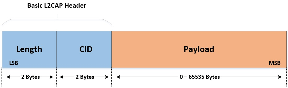
Figure 31 L2CAP PDU format in Basic L2CAP mode on COC
Summarizing:
L2CAP implementations transfer data between upper layer protocols and the lower layer protocol.
L2CAP maps channels to Controller logical links, which in turn run over Controller physical links. All logical links going between a local Controller and remote Controller run over a single physical link.
L2CAP is packet-based but follows a communication model based on channels. A channel represents a data flow between L2CAP entities in remote devices. Channels may be connection-oriented or connectionless. Fixed channels other than the L2CAP connectionless channel (CID
0x0002) and the two L2CAP signaling channels (CIDs0x0001and0x0005) are considered connection-oriented. All channels with dynamically assigned CIDs are connection-oriented.
5.1.13.1. Credit-Based Flow Control
The Credit-Based Flow Control is an L2CAP mode of operation that when used, allows both devices involved in the LE connection to have complete control over how many packets the peer device is allowed to send. This is achieved by the use of credits that represent the absolute maximum number of LE frames that the device is willing to accept at a particular moment. The sending entity may send only as many LE-frames as it has credits. If the credit count reaches zero the transmission must stop. If more frames are sent the connection will be closed.
5.1.13.2. Functions
To establish an LE-Credit Based L2CAP connection, the initiator should send a LE Credit-Based connection request, specifying parameters like the Protocol Service Multiplexer (PSM), Maximum Transmission Unit (MTU), Maximum Payload Size (MPS), and the initial number of credits that the remote peer has to send data. The responding device should respond with a LE Credit-Based Connection Response specifying its own MTU, MPS and initial credits value. PSM is 2-byte odd number that can be used to support multiple implementations of a protocol. The valid range for PSM is between 0x80 - 0xFF. The fixed SIG assigned PSM values are between 0x00 and 0x7F. MTU represents the maximum size of data that the service above L2CAP can send to the remote peer (Maximum size of an SDU – Service Data Unit). MPS is the maximum payload size that an L2CAP entity can receive from the lower layer, and it is equivalent to the maximum PDU payload size. Each MPS corresponds to one credit. One SDU (of size MTU) can be fragmented to one or more PDUs (of size MPS). If the SDU length field value exceeds the receiver’s MTU, the receiver shall disconnect the channel. If the payload length of any LE-frame exceeds the receiver’s MPS, the receiver shall disconnect the channel. If the sum of the payload lengths for the LE-frames exceeds the specified SDU length, the receiver shall disconnect the channel. After the LE Credit-Based connection request and response frames are received or exchanged, the two entities agree to use the minimum values of MTU and MPS.
As an example, consider two devices that use the following values during the Credit-Based connection request/response procedure:
Device A Connection Request |
Device B Connection Response |
|
|---|---|---|
PSM |
0x80 |
- (Field not available on Connection Response) |
MTU |
100 |
250 |
MPS |
50 |
23 |
Initial Credits |
10 |
20 |
In this scenario, device B can receive PDUs of size at most 23, and SDUs of size at most 250. On the other hand, device A can receive PDUs of size at most 100, and SDUs of size at most 50. Device A can send 20 PDUs to device B, and should stop until device B updates the available credits. This update could be performed any time during the connection. If device A was to transmit an SDU of size 100 bytes (MTU), it would be fragmented to 5 PDUs of data sizes 21, 23, 23, 23 and 10 respectively. This transmission would consume 5 credits (one credit for every PDU that could be received from device B). Note that the usable payload size of the first PDU is 2 bytes less than the value of MPS as the first LE-frame contains a 2-byte field specifying the total length of the SDU. This is true only for the first frame. In the same manner, the transmission of a 23-byte SDU would require two credits and two PDUs of size 21 and 2 bytes respectively whereas the transmission of a 21-byte SDU would require just one PDU. Maximum SDU length (MTU) can be specified using the ble_gap_mtu_size_set() API call.
API call |
Description |
|---|---|
ble_l2cap_connect() |
Create a l2cap connection oriented channel with remote peer. Connection establishment will be signaled using |
ble_l2cap_listen() |
Create a connection oriented channel listening for incoming connections. Incoming connection will be signaled using |
ble_l2cap_listen_defer_setup() |
Create a connection oriented channel listening for incoming connections. Incoming connection will be signaled using |
ble_l2cap_connection_cfm() |
Accept or reject incoming connection. Accepted connection will be signaled using |
ble_l2cap_stop_listen() |
Stop listening for incoming connections. |
ble_l2cap_disconnect() |
Disconnect an established L2CAP channel. |
ble_l2cap_send() |
Send data on channel, response code is signaled using the |
ble_l2cap_add_credits() |
Provide additional credits to remote peer. |
5.1.13.3. Events
Event |
Argument |
Description |
|---|---|---|
BLE_EVT_L2CAP_CONNECTED |
ble_evt_l2cap_connected_t |
Channel connected. Members |
BLE_EVT_L2CAP_CONNECTION_FAILED |
ble_evt_l2cap_connection_failed_t |
Channel connection failed. Member |
BLE_EVT_L2CAP_CONNECTION_REQ |
ble_evt_l2cap_connection_req_t |
Request connection. Members refer to connection parameters e.g. |
BLE_EVT_L2CAP_DISCONNECTED |
ble_evt_l2cap_disconnected_t |
Channel disconnected. Member |
BLE_EVT_L2CAP_SENT |
ble_evt_l2cap_sent_t |
Data sent on channel. |
BLE_EVT_L2CAP_REMOTE_CREDITS_CHANGED |
ble_evt_l2cap_credit_changed_t |
Available remote credits changed on channel. |
BLE_EVT_L2CAP_DATA_IND |
ble_evt_l2cap_data_ind_t |
Data received on channel. |
5.1.14. LE Data Packet Length Extension
For Bluetooth Core versions 4.0 and 4.1 the maximum Packet Data Unit (PDU) size was 27 octets. Bluetooth Core version 4.2 introduced an important enhancement, namely LE Data Packet Length Extension, which allows for the PDU size to be anywhere between 27 and 251 octets. This means that, for example, the L2CAP layer can now fill up to 247 octets of higher layer data packets in every L2CAP PDU compared to 21 octets with previous Bluetooth Core versions. This significant increase (more than 10 times) in the number of octets of user data sent per packet allows devices to transfer data up to 2.5 times faster than with previous versions. This will be of great benefit to applications that might require transferring large amounts of data such as Over-the-Air (OTA) firmware updates or downloading large data logs from sensors.
For the default PDU size to be extended on an established connection, the Data Length Update procedure must be performed. According to this control procedure, the LL_LENGTH_REQ and LL_LENGTH_RSP PDUs must be exchanged by the connected devices so that each is notified of its peer device’s capabilities. Each device uses these PDUs to report its maximum receive data channel and maximum transmit data channel PDU payload length and PDU time. After this update procedure, the PDU size for each direction of the connection’s data path is set by both controllers to the minimum of the values exchanged.
The DA1459x supports the LE Data Length Extension feature, so the values for the Receive and Transmit Data Length are set by default to the maximum allowed, which is 251 octets. The DA1459x controller when configured as a BLE central device will initiate a Data Length Update upon a new connection if the peer device’s controller supports this feature. The BLE Manager will use the values defined by dg_configBLE_DATA_LENGTH_RX_MAX and dg_configBLE_DATA_LENGTH_TX_MAX macros for this initial Data Length Update negotiation.
5.1.14.1. Functions
Function |
Description |
|---|---|
ble_gap_data_length_set() |
Set the maximum Transmit data length and time for an existing connection or the preferred Transmit data length for future connections (that is, the Transmit data length to be used in future data length update negotiations). Connection data length change will be signaled using |
5.1.14.2. Macros
Macro |
Default |
Description |
|---|---|---|
dg_configBLE_DATA_LENGTH_RX_MAX |
251 |
Set the maximum Receive Data Channel PDU Payload Length. Unless |
dg_configBLE_DATA_LENGTH_TX_MAX |
251 |
Set the maximum Transmit Data Channel PDU Payload Length. Unless |
5.1.14.3. Events
Event |
Argument |
Description |
|---|---|---|
BLE_EVT_GAP_DATA_LENGTH_CHANGED |
ble_evt_gap_data_length_changed_t |
Data Length changed for specified connection. Members |
BLE_EVT_GAP_DATA_LENGTH_SET_FAILED |
ble_evt_gap_data_length_set_failed_t |
Data Length Set operation failed. Member |
5.1.15. 2M PHY
Bluetooth Core versions up to 4.2 supported only the mandatory bit rate of 1 megabit per second (Mb/s), which is referred to as the LE 1M PHY. Bluetooth Core version 5.2, which is implemented in Renesas DA1459x product family, also supports the optional bit rate of 2 Mb/s, which is referred to as the LE 2M PHY. This feature is implemented by the LE controller and it can be configured using the API described in Section 5.1.15.1 and Section 5.1.15.2, although additional configuration is not mandatory; the LE controller will handle PHY update procedures seamlessly and will inform the application of any changes in the PHY configuration regardless of which side initiated the PHY update procedure.
5.1.15.1. Functions
Function |
Description |
|---|---|
ble_gap_phy_get() |
Get the transmitter and receiver PHY preferences set for an existing connection or for all future connections. The changes in PHY configuration for a given connection will be signaled using |
ble_gap_phy_set() |
Set the transmitter and receiver PHY preferences for an existing connection or for all future connections. Completion of the PHY set operation will be signaled using |
5.1.15.2. Events
Event |
Argument |
Description |
|---|---|---|
BLE_EVT_GAP_PHY_CHANGED |
ble_evt_gap_phy_changed_t |
PHY configuration changed for the specified connection. Members |
BLE_EVT_GAP_PHY_SET_COMPLETED |
ble_evt_gap_phy_set_completed_t |
PHY set operation has completed. This will be received following a ble_gap_phy_set() call. Member |
5.1.16. NVPARAM fields
Table 54 shows the Non-Volatile memory parameters which can be found in <SDK_ROOT_PATH>/sdk/middleware/adapters/include/platform_nvparam.h
Tag |
Offset |
Length |
|---|---|---|
NVPARAM_BLE_PLATFORM_BD_ADDRESS |
0x01 |
6 bytes array |
NVPARAM_BLE_PLATFORM_LPCLK_DRIFT |
0x07 |
16bit value |
NVPARAM_BLE_PLATFORM_EXT_WAKEUP_TIME |
0x0D |
16bit value |
NVPARAM_BLE_PLATFORM_OSC_WAKEUP_TIME |
0x0E |
16bit value |
NVPARAM_BLE_PLATFORM_RM_WAKEUP_TIME |
0x0F |
16bit value |
NVPARAM_BLE_PLATFORM_SLEEP_ENABLE |
0x11 |
1 byte |
NVPARAM_BLE_PLATFORM_EXT_WAKEUP_ENABLE |
0x12 |
1 byte |
NVPARAM_BLE_PLATFORM_BLE_CA_TIMER_DUR |
0x40 |
16bit value |
NVPARAM_BLE_PLATFORM_BLE_CRA_TIMER_DUR |
0x41 |
1 byte |
NVPARAM_BLE_PLATFORM_BLE_CA_MIN_RSSI |
0x42 |
1 byte |
NVPARAM_BLE_PLATFORM_BLE_CA_NB_PKT |
0x43 |
16bit value |
NVPARAM_BLE_PLATFORM_BLE_CA_NB_BAD_PKT |
0x44 |
16bit value |
NVPARAM_BLE_PLATFORM_IRK |
0x80 |
16 bytes array |
5.1.17. Considerations on BLE Task Priorities
The BLE Software in the SDK consists of three modules:
BLE manager: Provides the interface to the BLE functionality of the chip. The application task uses the BLE API to interface with the BLE manager. The BLE manager is a task that stands between the application and the BLE adapter. It uses the BLE adapter to interface with the BLE Stack.
BLE adapter: The system task that provides the interface to the BLE Stack. It runs the BLE Stack internal scheduler, receives the commands or the replies to events from the BLE manager, and passes BLE Stack events to the BLE manager. BLE core functionality is implemented by the BLE adapter task.
BLE Stack: The software stack that implements the Link Layer and the BLE Host stack, specifically the Logical Link Control and Adaptation Protocol (L2CAP), the Security Manager Protocol (SMP), the Attribute Protocol (ATT), the Generic Attribute Profile (GATT) and the Generic Access Profile (GAP).
Note
The BLE Stack software is run under the BLE adapter’s task context, which instantiates and initializes the stack.
The two BLE system tasks have by default a higher priority than application tasks in the SDK.
Note
Application developers should always make sure BLE adapter and BLE manager tasks always have a higher priority than application tasks.
The BLE adapter runs the BLE Stack scheduler, which dispatches all the messages between the BLE Stack’s different layers and calls the appropriate handlers. For example, when an application uses API ble_gatts_send_event() to send a GATT notification, this will result in a propagation of messages between the BLE manager, the BLE adapter and several BLE Stack’s internal layers until it reaches a transmission buffer and, eventually, the air.
5.1.18. BLE tasks timing requirement
In DA1459x the LE controller runs independently from the application. However, the BLE system tasks (BLE adapter, BLE manager) still need to run regularly to make sure BLE data are transmitted and handled in a timely manner. When the application is not making any BLE API calls and no data are exchanged with the peer, the BLE adapter will typically block until it is needed to either retrieve a message from or send a command to the BLE Host.
In some scenarios the BLE manager and the BLE adapter will communicate with messages without notifying the application. For example, upon connection with a peer that uses a resolvable private address, the BLE manager will attempt to resolve it using known devices IRKs. In this case the BLE manager and BLE adapter will have more running slots.
There are also other cases when the BLE framework will require a reply from the application when, for example, a pair request or a write request is received from the peer. Again, in these cases the BLE adapter and BLE manager will have to run more times in a period between two connection events.
5.1.19. Attribute operations
As the Attribute protocol is strict when an attribute request such as a read or a write request is received, the BLE Stack’s GATT layer will switch to a busy state for as long as the request is not completed/handled. In the case of a write request or a read request of an attribute whose value is to be provided by the application, then the application will have to confirm these operations using ble_gatts_read_cfm() or ble_gatts_write_cfm() respectively (after receiving BLE_EVT_GATTS_READ_REQ or BLE_EVT_GATTS_WRITE_REQ). In this case, other GATT operations, such as notification sending, will be queued until this request is confirmed.
5.1.20. BLE Application Examples
5.1.20.1. Advertising Application
The simplest BLE project in the DA1459x SDK is ble_adv demo which is found in the folder <SDK_ROOT_PATH>/projects/dk_apps/demos/ble_adv. The application starts the device as a peripheral, sets the device name and advertising data and starts advertising. Code 30 is an extract from main.c.
// Start BLE module as a peripheral device
ble_peripheral_start();

// Set device name
ble_gap_device_name_set("Dialog ADV Demo", ATT_PERM_READ);

// Set advertising data
ble_gap_adv_data_set(sizeof(adv_data), adv_data, 0, NULL);

// Start advertising
ble_gap_adv_start(GAP_CONN_MODE_UNDIRECTED);
No BLE service is added, and the ones exposed are just GAP and GATT
services. The infinite loop that implements the lifetime behavior of the
application uses just ble_get_event(true) to block indefinitely on the
BLE manager’s event queue. As soon as an event is posted there, the task
unblocks and handles it using a switch case. Code 31 is located in
main.c.
for (;;) {
             ble_evt_hdr_t *hdr;

             /* notify watchdog on each loop */
             sys_watchdog_notify(wdog_id);

             /* suspend watchdog while blocking on ble_get_event() */
             sys_watchdog_suspend(wdog_id);

             /*
              * Wait for a BLE event - this task will block
              * indefinitely until something is received.
              */
             hdr = ble_get_event(true);

             /* resume watchdog */
             sys_watchdog_notify_and_resume(wdog_id);

             if (!hdr) {
                     continue;
             }

             switch (hdr->evt_code) {
             case BLE_EVT_GAP_CONNECTED:
                     handle_evt_gap_connected((ble_evt_gap_connected_t *) hdr);
                     break;
             case BLE_EVT_GAP_DISCONNECTED:
                     handle_evt_gap_disconnected((ble_evt_gap_disconnected_t *) hdr);
                     break;
             case BLE_EVT_GAP_PAIR_REQ:
             {
                     ble_evt_gap_pair_req_t *evt = (ble_evt_gap_pair_req_t *) hdr;
                     ble_gap_pair_reply(evt->conn_idx, true, evt->bond);
                     break;
             }
             default:
                     ble_handle_event_default(hdr);
                     break;
             }

             // Free event buffer
             OS_FREE(hdr);
     }
Since the BLE service framework is not used, the only events handled by the application are the three events handled by the switch case: connection, disconnection and pair request. This makes sense for this application as its only purpose is to start a connectable advertising, restart it in case of a disconnection and respond to pair requests from devices that require pairing/bonding upon connection.
Running this project will result in an advertising BLE peripheral device exposing GAP and GATT services. GAP service attributes can be read using any standard BLE central device.
The ble_peripheral project is a good starting point for developing BLE peripheral applications. It is found in folder <SDK_ROOT_PATH>/projects/dk_apps/features/ble_peripheral. Unlike other example projects, it does not implement a specific profile, but instead exposes several BLE services via a GATT server.
The application’s initialization is similar to other projects that implement BLE peripheral applications. It uses the BLE service framework to instantiate several BLE services:
Battery Service (multiple instance)
Current Time Service
Device Information Service
Scan Parameter Service
Renesas Debug Service
Custom User Service
In addition to Bluetooth SIG-adopted services, ble_peripheral project instantiates two more services, Renesas Debug Service and a custom user service.
The Renesas Debug Service can be used to interact with the services that the application exposes using a Control Point characteristic to write commands and receive notifications from. A detailed description of the ways to interact with the Renesas Debug Service is included in the readme.md file inside the project’s folder.
The custom user service does not define any specific functionality other than using 128-bit UUIDs for services, characteristics and descriptors. This custom service, referred to as myservice in the project source code, is an example of implementing a custom service using BLE API calls to create its attribute database. No specific functionality is defined when one of these attributes is read or written. More details on how to create and use custom services will be given in Section 5.1.23.
After the attribute database is created, the device will end-up advertising and it will wait for a connection event.
The ble_peripheral project uses the BLE service framework to handle service events, the application also defines handlers for connection, advertising completion and pair request events. The ble_peripheral project stands in terms of its completeness somewhere between the ble_adv demo and an application implementing a full BLE profile like the pxp_reporter.
The services the project will expose can be configured using the file config/ble_peripheral_config.h.
5.1.21. BLE profile projects
In addition to the projects described in the previous sections, there are several application projects that implement BLE profiles. These projects are more complex and provide a full implementation of BLE applications. As such they provide a good reference on how to combine the BLE functionality with several OS mechanisms, GPIO handling and interfacing with external sensors.
The implemented profiles are located under <SDK_ROOT_PATH>/projects/dk_apps/ble_profiles and listed below:
Apple Media Service (
AMS) - Client roleHID over GATT Profile (
HOGP) – Device role (hogp_device)HID over GATT Profile (
HOGP) – Host role (hogp_host)Heart Rate Profile – Sensor role (
hrp_sensor)Heart Rate Profile – Collector role (
hrp_collector)Proximity Profile – Reporter role (
pxp_reporter) located under<SDK_ROOT_PATH>/projects/dk_apps/demosWeight Scale Profile – Weight Scale role (
wsp_weightscale)Apple Notification Center Service (
ANCS) - Notification Consumer (NC) role (ancs)Blood Pressure Profile (
BLP) – Blood Pressure Sensor role (blp_sensor)Bond Management Service (
BMS)Cycling Speed And Cadence collector (
CSCP)
5.1.22. Using adopted BLE services
Table 55 summarizes the API header files of the BLE services implemented by the DA1459x SDK. These files can be found under <SDK_ROOT_PATH>/sdk/interfaces/ble/services/include. The developer can use these APIs to add these services to another project.
File name |
Description |
|---|---|
ble_service.h |
BLE service framework API:
|
bls.h |
Blood Pressure Service – BLS |
bas.h |
Battery Service – BAS |
bcs.h |
Body Composition Service – BCS |
bms.h |
Bond Management Service – BMS |
cts.h |
Current Time Service – CTS |
dis.h |
Device Information Service – DIS |
dlg_debug.h |
Renesas Debug Service |
dlg_suota.h |
Renesas SUOTA Service |
hids.h |
Human Interface Device Service – HID |
hrs.h |
Heart Rate Service – HRS |
ias.h |
Immediate Alert Service – IAS |
lls.h |
Link Loss Service – LLS |
scps.h |
Scan Parameters Service – ScPS |
sps.h |
Serial Port Service – SPS |
tps.h |
Tx Power Service – TPS |
uds.h |
User Data Service – UDS |
wss.h |
Weight Scale Service – WSS |
5.1.23. Adding a custom service
The following code segments provide an overview of the initialization required to create a new custom service called XXX. It requires the files xxx.c and xxx.h to be created. A good example to base these on is the dlg_mls service in the Multi-Link demo. This provides a single write only characteristic in the service.
Each service needs a structure containing both the generic ble_service_t structure and any callbacks and characteristic handles required by the service. In the example below for service XXX there is one callback and one characteristic defined.
typedef struct {
     ble_service_t svc;          // Core BLE service structure
     xxx_cb_t cb;                // Callback provided by app to xxx
                                 // service to process an event
     uint16_t xxx_char1_val_h;   // Declare handle for each characteristic
                                 // that can be read or written
} xxx_service_t;
The requirements of the initialization function xxx_init() are illustrated below. They key information here is the comments which are explaining what each line is doing.
xxx_service_t* xxx_init(callback1){
// Allocate and initialise xxx_service_t structure
// Define any callback functions required by the service, write only in this case
xxx->svc.write_req = <this services write request handler>
// Create primary service UUID with either 16 or 128 bit value
uuid=ble_uuid_from_string() or uuid=ble_uuid_create16()
// add PRIMARY service with X attributes
num_attrs=X
ble_gatts_add_service(&uuid, GATT_SERVICE_PRIMARY, num_attrs)
// Create characteristic 1 for this service and allocate handle for it in GATT table
ble_gatts_add_characteristic(&uuid, GATT property, ATT permissions, size,0, NULL, &xxx->xxx_char1_h)
// Set start_h and pass in null terminated variable length list of all characteristic handles in the service
ble_gatts_register_service(&xxx->svc.start_h, &xxx->xxx_char1_h,0);
// Calculate end handle for service based on number of attributes in service
xxx->svc.end_h= xxx->svc.start_h + num_attrs;
// add the passed in callback function to service structure
xxx->xxx_cb1=callback1;
// add newly created service to ble framework
ble_service_add(&xxx->svc);
// and return handle for the service to the application
return &xxx->svc
}
5.1.24. Extending BLE functionality
The Renesas BLE API can be used to develop BLE applications. The API header files are located in folder <SDK_ROOT_PATH>/sdk/interfaces/ble/api/include. They are documented in [Ref_03] and are summarized in Table 56.
File name |
Description |
|---|---|
ble_att.h |
Attribute Protocol API: Mostly definitions. |
ble_attribdb.h |
Helper to manage complex attributes database. |
ble_bufops.h |
Helpers to put and get data from BLE buffers. |
ble_common.h |
Common API: Functions used for operations not specific to a certain BLE Host software component |
ble_gap.h |
GAP API:
|
ble_gatt.h |
Common definitions for GATT API |
ble_gattc.h |
GATT client API:
|
ble_gattc_util.h |
GATT client utilities |
ble_gatts.h |
GATT server API:
|
ble_l2cap |
BLE L2CAP API. |
ble_storage.h |
BLE persistent storage API. |
ble_uuid.h |
BLE UUID declarations and helper functions. |
5.2. Software Upgrade Over The Air (SUOTA)
5.2.1. Introduction
The DA1459x SDK allows the user to update the software of the device wirelessly, using the Software Upgrade Over The Air (SUOTA) procedure.
Depending on the available storage size and application requiremens the following options are offerred:
Dual bank SUOTA - Two equal in size image banks are used. One is the active image that is executed and one is the image that is updated. Application images are similar in functionality and they expose the SUOTA service and are capable to perform the software update.
Asymmetric SUOTA - Two asymmetric, i.e. different in size and functionality, image banks are used. This scheme enables having a larger main application image bank and utilizes a minimized in size and features application that exposes the SUOTA service and is the only one capable to perform a software update.
When an update procedure is initiated from an Android or iOS device, a new firmware image is first transferred to the Flash memory and then the device reboots to complete the update. The final verification and activation of the new image is performed by the ROM boot loader on the next reboot. For more information see Section 5.3.1.
The SUOTA GATT server runs on the DA1459x device and the GATT client on the Android or iOS device running the SUOTA application.
Important
RED Compliance
The following updates have been implemented in the SUOTA service for the DA1459x series to ensure compliance with the Radio Equipment Directive (RED):
A basic anti-rollback prevention mechanism is incorporated into the SUOTA service for the DA1459x series. This mechanism compares the firmware version of the current image with that of the new image before proceeding with the update. Additionally, the CRC field is utilized to provide an enhancement in protection against rollback attempts. If the version of the new image is lower than the existing one’s, the
suota_state_w4_header()returns false rejecting the SUOTA update. The SUOTA application remains at 0%, and the device disconnects. However, the application remains responsive, allowing for a new SUOTA update to be initiated.This update introduces the
CONFIG_SUOTA_VERSION_CHECK_ENABLEmacro, which is enabled by default to provide anti-rollback protection. It allows users to enable or disable the SUOTA firmware version check as needed.SUOTA now enforces secure connections. Any SUOTA request must originate from a secure connection; otherwise, it will be rejected. This ensures that firmware updates are performed only over trusted, authenticated links.
5.2.2. SUOTA service description
This section gives a brief description of the SUOTA service, responsible for performing software upgrades over BLE. A detailed service characteristic description is given on Table 57.
Characteris tic |
SUOTA Version (SUOTA_VERS ION definition) |
Access |
Size |
Description |
|---|---|---|---|---|
MEM_DEV |
since version v1.3 |
READ WRITE |
4 |
Using this characteristic the GATT client is able to send commands to the SUOTA service. Some of the most commonly used commands are the following:
|
GPIO MAP |
READ WRITE |
4 |
Used to specify GPIO map of external FLASH device. Currently not applicable. |
|
MEM_INFO |
READ |
4 |
Stores the total number of bytes received until now. |
|
PATCH_LEN |
since version v1.3 |
READ WRITE |
2 |
Specifies the number of bytes that when received, will trigger a notification back to the GATT client. This is meant to be used for flow control. The exact value is set by the GATT client during SUOTA. The notification is generated from the “STATUS” characteristic |
PATCH_DATA |
since version v1.3 |
READ WRITE WRITE_NO_RE SP |
Exact size is specified by PATCH_DATA CHAR_SIZE |
This is the endpoint to which SUOTA image data are sent. The exact size is specified by the “PATCH_DATA CHAR_SIZE” characteristic, and different values (23 – 509) can be used depending on the throughput requirements |
STATUS |
since version v1.3 |
READ NOTIFY |
1 |
This characteristic is used to notify the GATT client of the status of the SUOTA process. Status notifications are sent to indicate error conditions (for example bad command, or CRC) or to allow flow control during SUOTA process. |
L2CAP_PSM |
since version v1.3 |
READ |
2 |
This is an optional characteristic that, if exists, indicates that the SUOTA service supports both SUOTA over GATT and SUOTA over L2CAP CoC. The value indicates the dynamic L2CAP channel on which the SUOTA service is listening for connections. The absence of this characteristic indicates that only SUOTA over GATT is supported. |
VERSION |
since version v1.3 |
READ |
1 |
Indicates the version of the SUOTA service. The value is retrieved from the “SUOTA_VERSION” definition. |
MTU |
since version v1.3 |
READ |
2 |
Stores the current value of the MTU, which is going to be either 23 (default), or a bigger value, if MTU exchange took place. This value can be used by the GATT client to retrieve the MTU size (if such API is not available on its side) and write with optimal rate to the “PATCH_DATA” characteristic. |
PATCH_DATA CHAR_SIZE |
since version v1.3 |
READ |
2 |
Specifies the size of the “PATCH_DATA” characteristic. |
CCC |
READ WRITE |
1 |
Client Characteristic Configuration Allows the GATT client to enable notifications from the “STATUS” source. |
Once the SUOTA service is discovered on the remote device and the GATT client
has enabled notifications by writing the CCC characteristic, the SUOTA
procedure can be started by issuing the SPOTAR_IMG_SPI_FLASH command.
The write command executes successfully only if:
No more than one device is currently connected to the SUOTA enabled device
The application hosted in the SUOTA enabled device allows the upgrade to take place
There is enough memory to allocate the internal working buffers
If any of the above restrictions is violated, then command fails and an
error notification is sent back to the GATT client (status SUOTA_SRV_EXIT).
After a successful command execution the service is able to receive data
either over GATT or L2CAP CoC layer (if the L2CAP_PSM characteristic is
available).
The GATT client can use the value of the characteristic MTU to perform ATT
write commands to the characteristic PATCH_DATA with optimal size if
the GATT Client (mobile phone) has no API to find the optimal packet size.
It is also possible for the GATT client to retrieve the size of the PATCH_DATA
characteristic by reading the PATCH_DATA_CHAR_SIZE characteristic.
Following this, the GATT client should specify the value of the patch_len
variable by writing the PATCH_LEN characteristic. PATCH_LEN specifies
the number of bytes that once received, will trigger a notification back to
the GATT client. This kind of flow control could be used to
avoid flooding the SUOTA enabled device with too much image data. The
bigger the value, the better the throughput, since notifications are
going to be generated less frequently and therefore the number of missed
connection events (where flow has stopped waiting for the notification)
is decreased.
For example, if patch_len is set to 500 bytes, notifications will
be sent to the GATT client when byte ranges 1-500, 501-1000, 1001 – 1500 etc.
are received. Following the Bluetooth low energy specification, the
maximum number of bytes that can be written to the PATCH_DATA
characteristic with a single ATT write command is the minimum of MTU – 3
and the size of the PATCH_DATA characteristic.
When the whole image has been sent, the GATT client should issue the
SPOTAR_IMG_END command to indicate this to the SUOTA service. The
service is going to perform some sanity checks to verify that image
transfer took place without errors, and then it is going to generate the
appropriate status notification (SUOTA_CMP_OK on success,
SUOTA_APP_ERROR or SUOTA_CRC_ERR on error).
Finally, the GATT client could issue an SPOTAR_REBOOT command to force a
device reboot. This step is optional, but it is highly recommended.
Note
The PATCH_DATA, PATCH_DATA_CHAR_SIZE and PATCH_LEN characteristics
are only relevant when SUOTA over GATT is taking place. When L2CAP
CoC are used, a connection should be established to the L2CAP_PSM
channel via L2CAP CoC and the flow is controlled using L2CAP credits.
SUOTA service assigns enough credits to ensure that flow won’t stop
during the upgrade. Notifications relevant to the PATCH_LEN
characteristic are not sent during image transfer, but all other
notifications are still valid.
5.2.3. Dual Bank SUOTA Flow
Figure 32 and Figure 33 illustrate the abstract FW update steps. Figure 34 illustrates in detail the flow diagram of the SUOTA.
The final verification and activation of the new image is performed by the ROM boot loader on the next reboot.
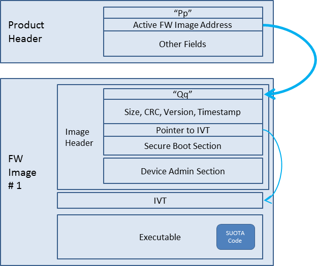
Figure 32 Flash layout after initial programming during production
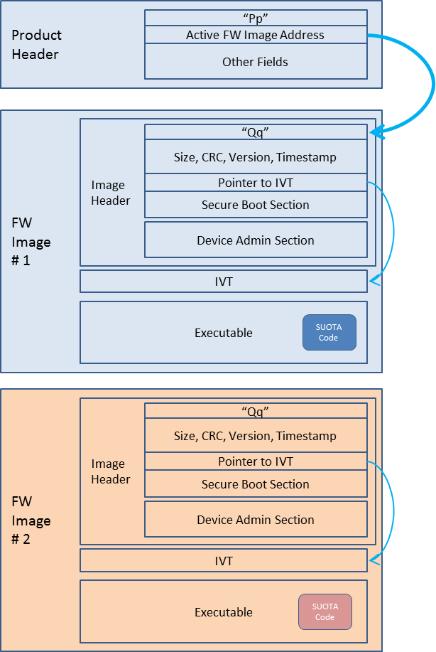
Figure 33 Flash image layout after SUOTA image written in the destination partition
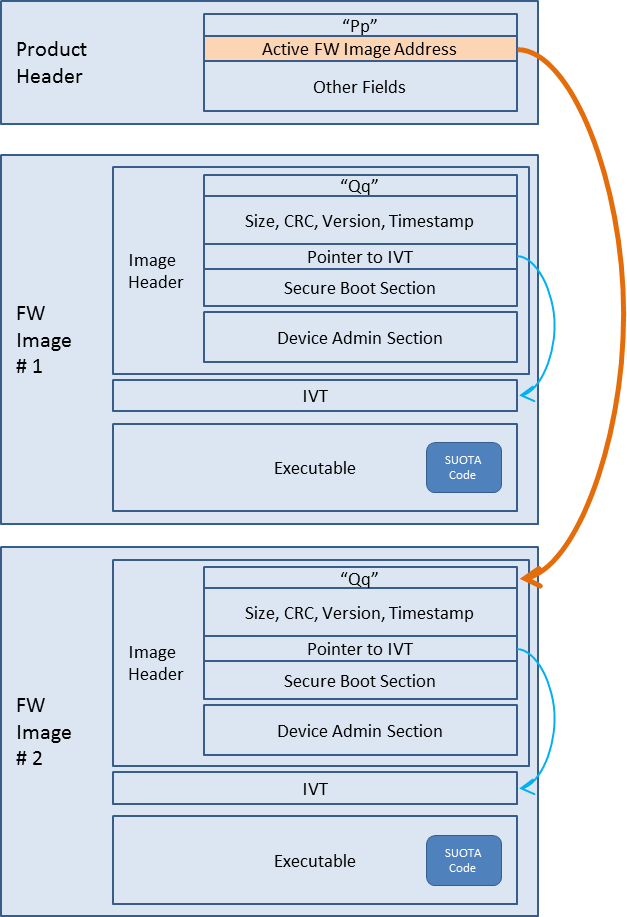
Figure 34 Flash image layout after reboot and activation of the new image
5.2.4. Performing SUOTA upgrade using a mobile phone
Note
The following procedure applies when using Android or iOS devices
5.2.4.1. Preparing the SUOTA enabled device
Build the pxp_reporter application using the
DA1459x-00-Release_eFLASH_SUOTAorDA1459x-00-Release_QSPI_SUOTAconfiguration for executing code in place from eFlash or QSPI respectively.Erase the Embedded or the QSPI Flash memory of DA1459x using the
erase_eflash_jtagorerase_qspi_jtagscript respectively.Download the pxp_reporter binary to DA1459x using the
eFLASH_DA1459xorQSPI_DA1459xdebug launcher for the Embedded or QSPI flash respectively.
Press the K2 (Reset) button on the DK daughter board. PXP Reporter application should start running.
5.2.4.2. Preparing the SUOTA image
A SUOTA image is a binary file with a proper header that can be sent to a target device from an Android or iOS device.
To prepare a SUOTA image using PXP Reporter demo application, perform the following steps:
Import the following two projects into e² studio from these locations.
python_scripts:
<SDK_ROOT_PATH>\utilitiespxp_reporter:
<SDK_ROOT_PATH>\projects\dk_apps\demos
Build the pxp_reporter application using the
DA1459x-00-Release_eFLASH_SUOTAorDA1459x-00-Release_QSPI_SUOTAbuild configuration for executing code in place from eFlash or QSPI respectively. A new image namedpxp_reporter.imgis also created under the build folder.
5.2.4.3. Perform the SUOTA using the mobile application
Download the Renesas SUOTA application from Google PlayStore or Apple App Store.
Copy
pxp_reporter.imgto an Android phone or tablet or to an iOS device and place it into the SUOTA folder. The folder is automatically created, if it does not exist, on the device by running the “SUOTA” application. On Android it is located at the root directory of the “Internal Storage” drive.Launch the Renesas SUOTA application on the Android phone and select the DA1459x device you want to update.
Figure 35 Device selection
Select Update device.
Figure 36 Update device
Select the appropriate image file – this is a list of the files in the SUOTA directory.

Figure 37 Image file
Touch Send to device on the touchscreen
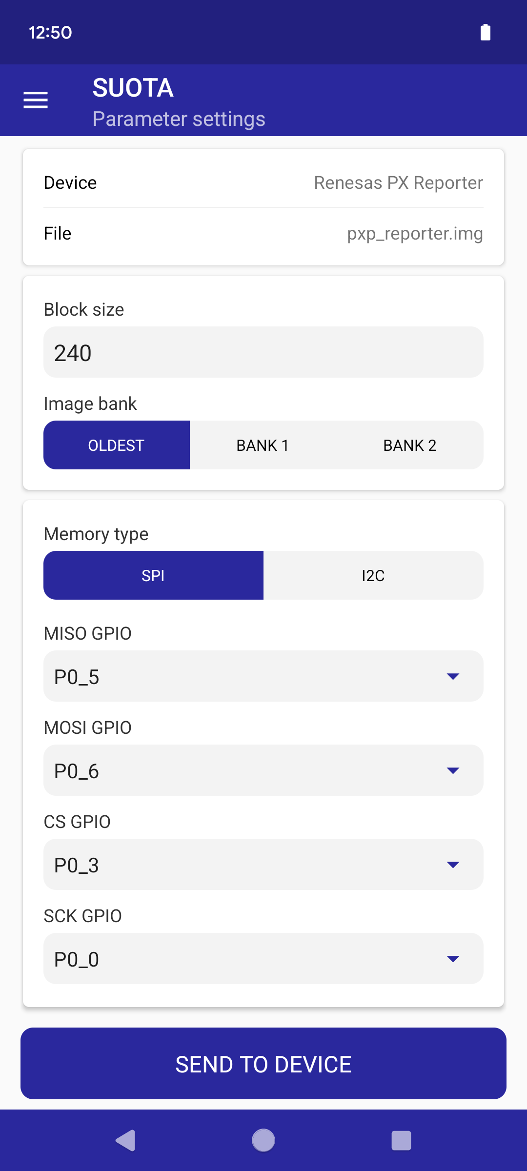
Figure 38 Parameter settings for SPI
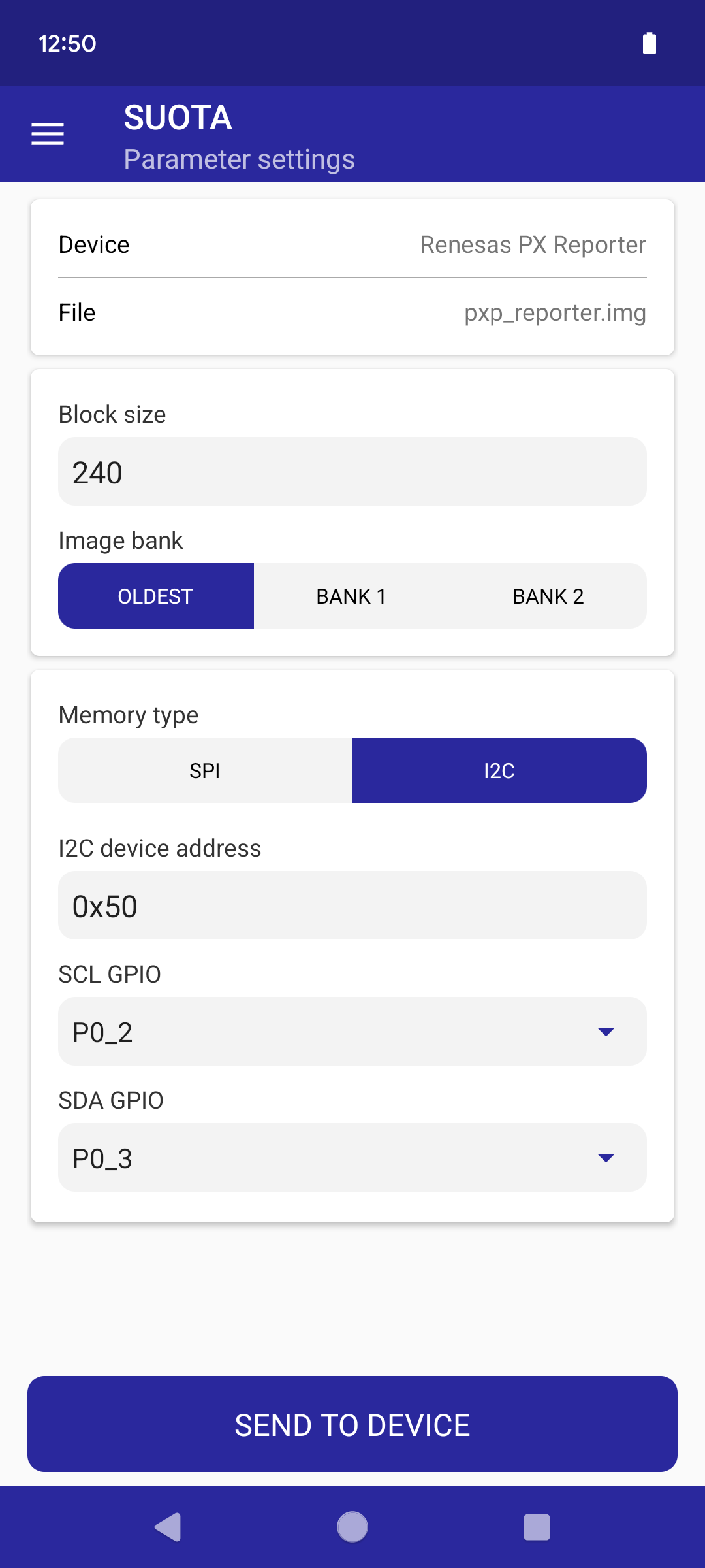
Figure 39 Parameter settings for I2C
Wait until the process is completed. When the image is uploaded, a Renesas box pops up asking for a device reboot. Select OK.
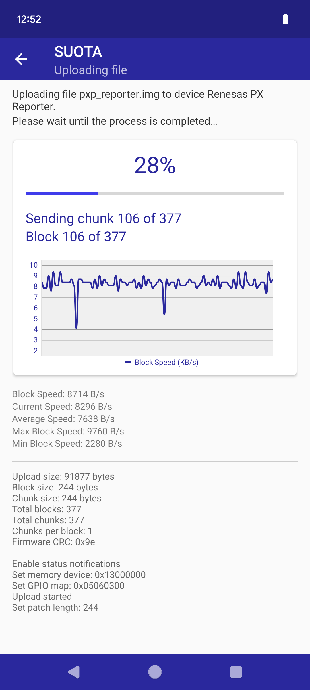
Figure 40 Uploading the image file
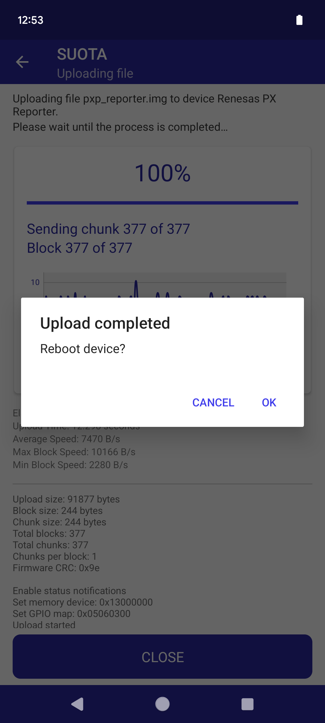
Figure 41 Reboot device
Press Close to return to the main menu.
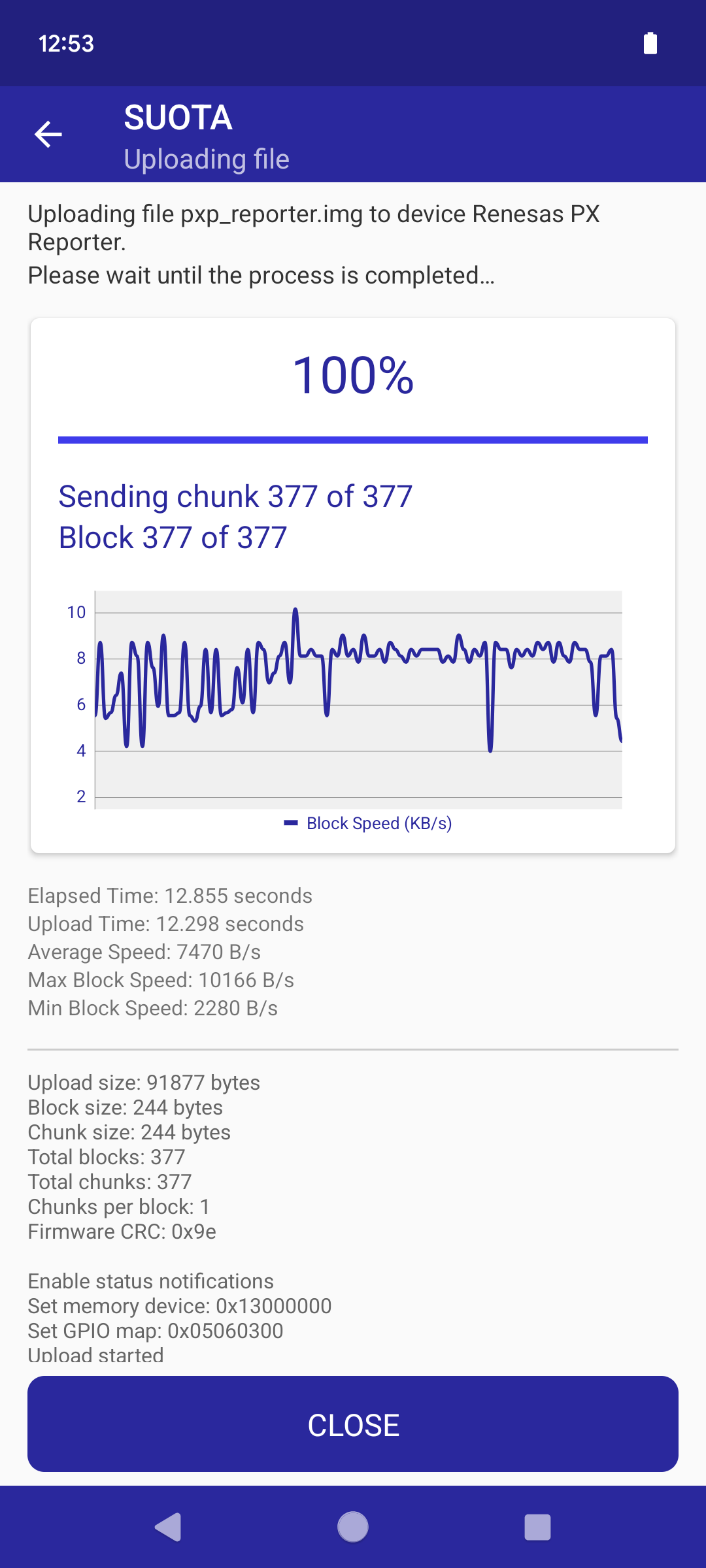
Figure 42 When file upload is finished, press “Close”
5.2.4.4. Performing SUOTA upgrade using two DA1459x devices
This section describes the procedure for performing SUOTA using two DA1459x devices.
One acting as the BLE central. It performs as the SUOTA image transmitter running
ble_suota_clientapplication. The SUOTA image will be stored in the NVMS_BIN_PART NVMS partition.One acting as the BLE peripheral. It performs as the SUOTA image receiver, running
pxp_reporterapplication.
Using this setup, it is possible to test both SUOTA methods (over GATT and over L2CAP Connection-Oriented Channels) without using any phone. The image to be transferred is stored in the NVMS_BIN_PART partition in the Flash memory of the BLE central device.
5.2.4.5. Preparing the SUOTA enabled device pxp_reporter
Follow the steps described in Section 5.2.4.1
As soon as eFLASH_DA1459x debug launcher is executed, a new window pops up asking to choose
which device is the target; select the appropriate device.
Figure 43 Selecting target device
5.2.4.6. Preparing the SUOTA update image
See Section 5.2.4.2
5.2.4.7. Preparing the ble_suota_client device
5.2.4.8. Building the ble_suota_client application
Import the following projects using e² studio from the following locations:
python_scripts:
<SDK_ROOT_PATH>\utilitiesble_suota_client:
<SDK_ROOT_PATH>\projects\dk_apps\features
and select the following build configuration for the ble_suota_client project:
ble_suota_client in
DA1459x-00-Release_eFLASHconfiguration.
To build and install the ble_suota_client, follow the procedure below:
Build the project ble_suota_client by executing
DA1459x-00-Release_eFLASHErase the flash memory of the device by executing the
erase_eflash_jtagscript.Execute the
eFLASH_DA1459xdebug launcher to program the eFlash memory.
As soon as the script is executed, a new window pops up asking to choose which of the DKs is the target; select the appropriate device.
Figure 44 Selecting the target device
5.2.4.9. Storing the SUOTA update image in the ble_suota_client device
Note
The SUOTA update image was created in step Preparing the SUOTA update image
Use cli_programmer to download the binary pxp_reporter.img to the device.
<SDK_ROOT_PATH>\binaries\cli_programmer.exe <SERIAL_PORT> write_eflash 0x00 <SDK_ROOT_PATH>\projects\dk_apps\demos\pxp_reporter\DA1459x-Debug_eFLASH_SUOTA\pxp_reporter.img``
or
<SDK_ROOT_PATH>\binaries\cli_programmer.exe <SERIAL_PORT> write_qspi 0x00 <SDK_ROOT_PATH>\projects\dk_apps\demos\pxp_reporter\DA1459x-Debug_QSPI_SUOTA\pxp_reporter.img``
5.2.4.10. Performing the software upgrade procedure
When the previous procedure has finished, the two DA1459x devices are ready to communicate. To perform SUOTA on the PXP Reporter device, the following steps should be followed:
A serial terminal is needed to connect to the
ble_suota_clientdevice and perform the SUOTA. In the example below, “Real Term” is used for this purpose. Configure the serial terminal as follows:
Figure 45 Configuring the serial port
Connect to the serial port and press the
K2RESET button.
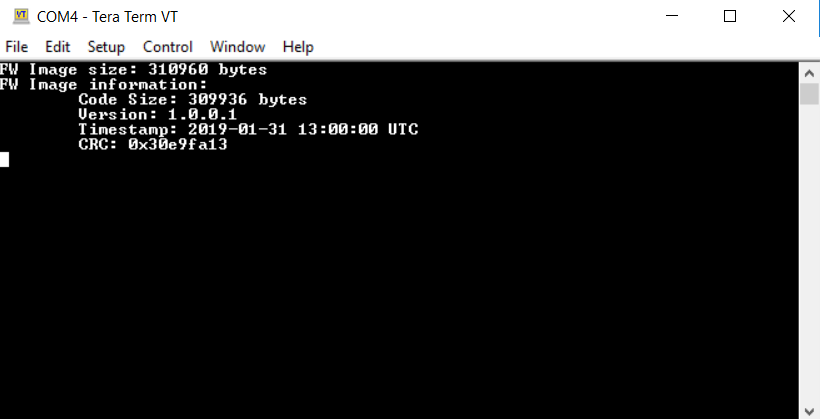
Figure 46 Connecting to the serial port
Information regarding the image stored in the NVMS_BIN_PART partition are displayed during boot
In the serial terminal of the
ble_suota_clientdevice, give the following command:> scan start
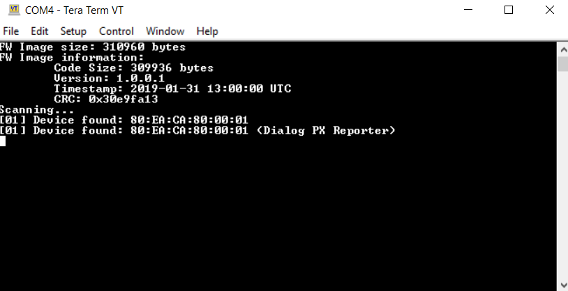
Figure 47 Scanning for available devices
The ble_suota_client device starts scanning for available
devices immediately (Figure 47). In this in example, from the devices
listed Figure 47, the pxp_reporter device, is the
device with sequence number [01].
As soon as the
pxp_reporterdevice is found, the scanning operation can be stopped with the following command:> scan stopA connection to the
pxp_reporterdevice can be initiated with the command:> connect 1
The first argument of the “connect” command refers to the device index on the scan result list. Once a connection is established, the application automatically queries the remote device for available services and device information. The characteristic values of the Device Information Service (DIS) are read. The following output is printed on the terminal:
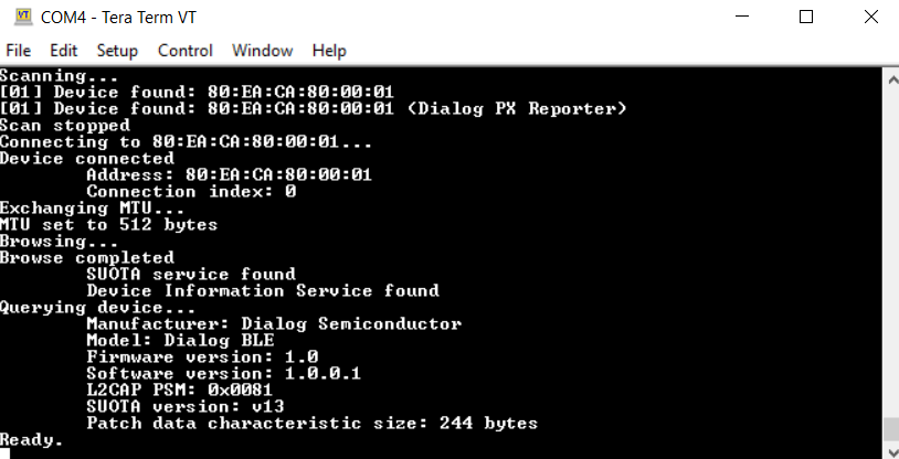
Figure 48 Connecting to loader device
The presence of “L2CAP PSM” indicates that the remote device supports SUOTA and over-L2CAP COC.
To update a device supporting L2CAP COC over L2CAP, issue the update command. To update the same device over GATT, issue the update gatt command. If the remote device does not support L2CAP COC (“L2CAP PSM” is not displayed), both update and update gatt commands begin SUOTA over GATT.
> update gatt
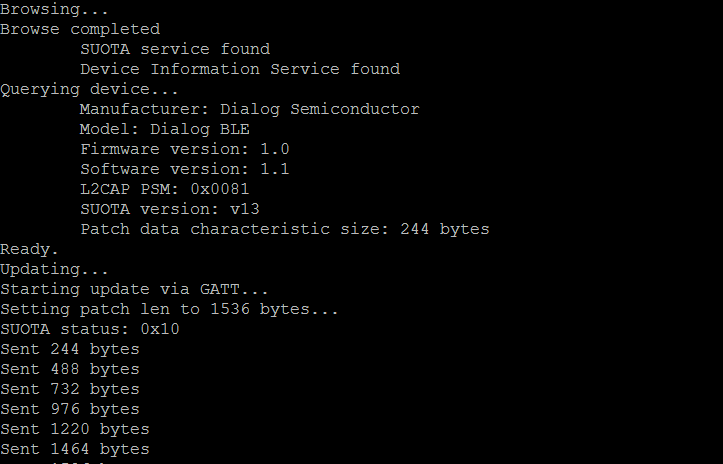
Figure 49 Updating with new image the loader device
After the image transfer has been completed, the remote device disconnects and reboot as shown in Figure 50.
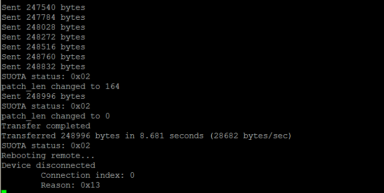
Figure 50 Transfer complete
When the pxp_reporter device reboots, execution of the new image begins.
The software upgrade has finished. Now the pxp_reporter
device should start advertising as <Renesas PX Reporter>. To
verify that, perfom the scan operation again by issuing the scan start command.
> scan start
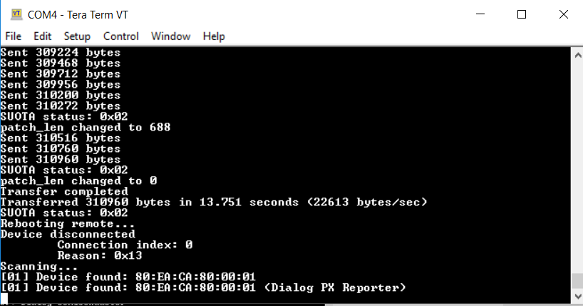
Figure 51 Verifying that loader is running PX Reporter
5.2.4.11. Asymmetric SUOTA Flow
Figure 52, Figure 53, Figure 54 and Figure 55 illustrate the Asymmetric SUOTA steps to update the application firmware image.
The verification and activation of the each image is performed by the ROM boot loader on each reboot.

Figure 52 Flash layout after initial programming during production
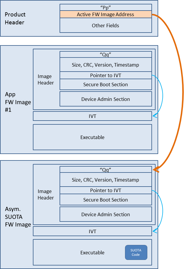
Figure 53 Flash image layout after Asymmetric SUOTA image is running
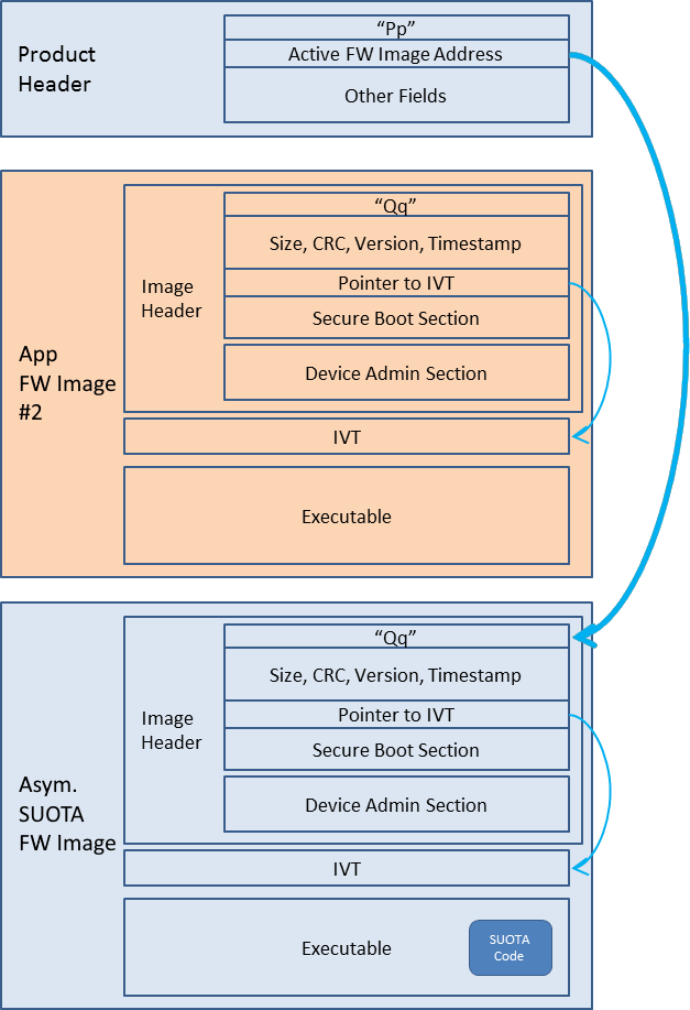
Figure 54 Flash image layout after application image written in the destination partition
Figure 55 Flash image layout after reboot and activation of the new image
5.2.4.12. Performing SUOTA upgrade of Asymmetric SUOTA firmware image
Asymmetric SUOTA firmware image can also be updated from the Asymmetric SUOTA firmware. To enable a safe update operation, the application firmware image bank is used as a temporary storage location. As a result, after an update of the Asymmetric SUOTA firmware image, the application firmware image is overwritten and an application firmware update must be executed afterwards to restore the application.
Figure 56, Figure 57, Figure 58, Figure 59 and Figure 60 illustrate the Asymmetric SUOTA steps to update the Asymmetric SUOTA firmware image. Figure 61 and Figure 62, illustrate the Asymmetric SUOTA steps to restore the application firmware image.
Figure 56 Flash layout after initial programming during production
Figure 57 Flash image layout after Asymmetric SUOTA image is running
Figure 58 Flash image layout after Asym. SUOTA image written in the application FW partition
Figure 59 Flash image layout after reboot, activation of the new image and self-copy to Asym. SUOTA destination partition
Figure 60 Flash image layout after reboot and activation of the final Asym. SUOTA image - No application image
Figure 61 Flash image layout after application image written in the application FW partition
Figure 62 Flash image layout after reboot and activation of the application FW
5.2.4.13. Performing SUOTA upgrade using a mobile phone
Note
The following procedure applies when using Android or iOS devices
5.2.4.14. Preparing the SUOTA enabled device
Build the asymmetric_suota application using the
DA1459x-00-Release_eFLASH_SUOTAconfiguration for executing code in place from eFlash.Build the ble_adv application using the
DA1459x-00-Release_eFLASH_SUOTA_ASYMconfiguration for executing code in place from eFlash.Erase the Embedded Flash memory of DA1459x using the
erase_eflash_jtagorerase_eflash_serialscripts.Download the asymmetric_suota binary to DA1459x using the
eFLASH_DA1459xdebug launcher.Download the ble_adv binary to DA1459x using the
eFLASH_DA1459xdebug launcher.
Note
Alternatively, the steps 4 and 5 can be replaced with the following:
Configure python eflash scripts using the
program_eflash_configscript and set the active image address at0x2FC00and the update image address at0x2000.Download both asymmetric_suota and ble_adv binaries by having selected the ble_adv project and using the
program_eflash_asuota_jtagorprogram_eflash_asuota_serial. The script will download both images in one step.
Press the K2 (Reset) button on the DK daughter board. BLE advertiser application should start running.
5.2.4.15. Preparing the SUOTA image
A SUOTA image is a binary file with a proper header that can be sent to a target device from an Android or iOS device. Asymmetric SUOTA supports updating both the main application firmware image and the Asymmetric SUOTA firmware image as well.
To prepare a SUOTA image using BLE advertiser demo application, perform the following steps:
Import the following two projects into e² studio from these locations.
python_scripts:
<SDK_ROOT_PATH>\utilitiesble_adv:
<SDK_ROOT_PATH>\projects\dk_apps\demos
Build the ble_adv application using the
DA1459x-00-Release_eFLASH_SUOTA_ASYMbuild configuration for executing code in place from eFlash. A new image namedble_adv.imgis also created under the build folder.
5.2.4.16. Perform the SUOTA using the mobile application
Download the Renesas SUOTA application from Google PlayStore or Apple App Store.
Copy
ble_adv.imgto an Android phone or tablet or to an iOS device and place it into the SUOTA folder. The folder is automatically created, if it does not exist, on the device by running the “SUOTA” application. On Android it is located at the root directory of the “Internal Storage” drive.Launch the Renesas SUOTA application on the Android phone and select the DA1459x device you want to update.

Figure 63 Device selection
Select Switch to SUOTA mode.
Figure 64 Switch to SUOTA mode
Wait for the device to reboot in SUOTA mode and connect.
Figure 65 Connecting to SUOTA mode
Select Update device.

Figure 66 Update device
Select the appropriate image file – this is a list of the files in the SUOTA directory.
Figure 67 Image file
Touch Send to device on the touchscreen

Figure 68 Parameter settings for SPI
Figure 69 Parameter settings for I2C
Wait until the process is completed. When the image is uploaded, a Renesas box pops up asking for a device reboot. Select OK.
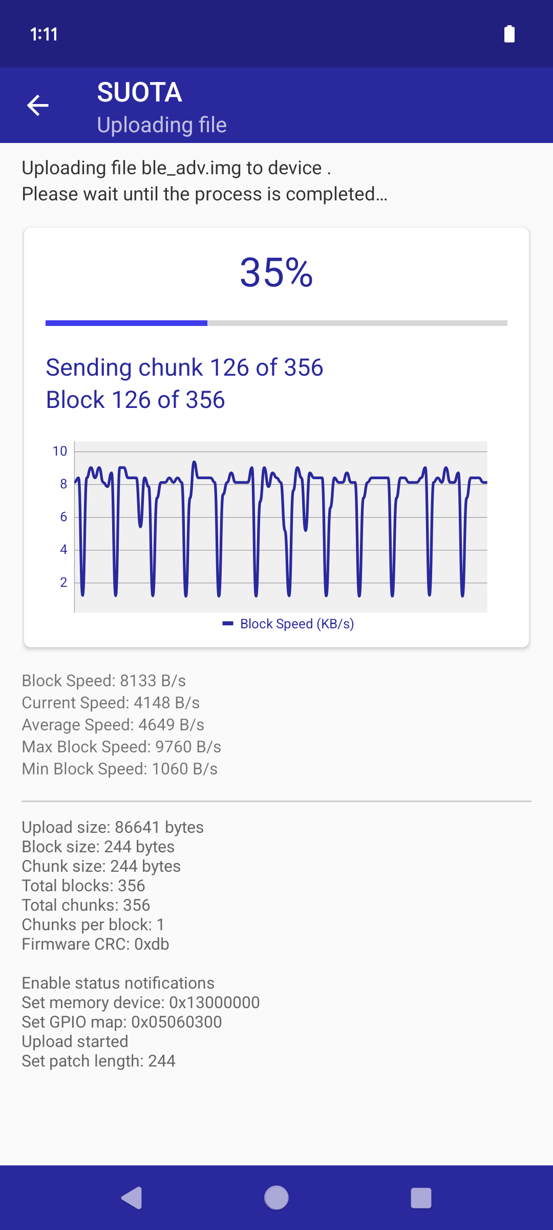
Figure 70 Uploading the image file
Figure 71 Reboot device
Press Close to return to the main menu.
Figure 72 When file upload is finished, press “Close”
5.3. Booting
The Boot ROM code is executed by SYSCPU (Cortex-M33) after a POR or HW Reset. As an additional capability it can be executed after wakeup when the RESET_ON_WAKEUP feature is configured.
The following booting options are supported:
Boot from the Embedded Flash memory with caching enabled and no security features, Configuration Script (CS) in Embedded Flash.
Boot from the Embedded Flash memory with both caching and security features enabled, Configuration Script (CS) in Embedded Flash.
Boot from the QSPI Flash memory with caching enabled and no security features, Configuration Script (CS) in QSPI Flash.
Boot from the QSPI Flash memory with both caching and security features enabled, Configuration Script (CS) in Embedded Flash.
Boot from UART without FLASH (Embedded, QSPI) or security features.
If neither a valid binary resides in any of the Flash mediums (Embedded, QSPI), nor is one provided via UART port, the booter will enter an endless loop.
The Configuration Script (CS) is a table of up to 256 32-bit entries. The booter will try to locate and execute the CS from Embedded or QSPI Flash memory. First will try to find the CS in Embedded Flash at address 0. If CS is not found, it will look at the start of QSPI Flash memory. The CS contains information related to booter, like Product header location, the development mode flag, entries which can be used by SDK or application software to apply some values to specific registers (address-value pair) or to use them as trim values for a subsystem. The sticky bits configuration is used to enable the secure features of the booter. For more info about the CS, please refer to the DA1459x datasheet chapter “System Overview”, paragraph “Booting”, section “Configuration Script”.
5.3.1. Boot flow
The boot flow is divided in five separate phases
Initialization: The booter takes care of configuring power domains and peripheral clocks. The boot code initializes the QSPI memory in order to be able to access it. It enables the Development Mode by default. In Development Mode the booter enables the debugger and it is also possible to update the devices firmware by UART. Development mode can be deactivated adding the corresponding entry in CS.
Run Configuration Script: The booter searches for the CS in the beginning of Embedded or QSPI Flash. If CS is found it starts parsing it and applies its directives, otherwise continues to next state.
Retrieve application code: This phase depends on Development mode.
Development mode enabled
The booter will enable the debugger and try to boot from UART. If it fails to retrieve an application from UART it will try to locate a valid product header.
If it finds a product header will continue to next phase otherwise will try to boot from UART again.
In case there is no valid product header the booter will enter an infinite loop. This loop is active until a boot is initiated from the UART or a debugger gets connected.
Development mode disabled
In this case both debugger and booting from UART feature are disabled. The booter tries to locate and parse the Product and image headers from FLASH (Embedded or QSPI). If these headers are invalid, the booter will enter an infinite loop.
- Device administration: The booter will first check if there is any pending update. In case of update it will validate the new firmware image and if the validation succeeds the booter
will accept the update. Otherwise, the booter will reject the update and try to validate the active (old) image. If the verification is valid, it will boot the old image. In case there is no pending update the booter will validate the active image. If validation fails, the booter will trigger a HW reset. Image validation depends on secure mode. The booter always checks for ‘Qq’ in the beginning of the image header and if the FW image is secure, then the booter performs the following additional verifications:
If the image header contains the security section (
0xAA22).If the image header contains the administration section (
0xAA44)If is able to extract public keys and signature verification value.
If the public key used for the signature verification is not revoked.
If the image signature generated with
Ed25519algorithm is valid.SW rollback prevention. The FW version in the image header should be higher or equal to the minimal FW version, stored in the CS protected area (This step runs only if a minimal FW version is set by the CS).
The image validation succeeds only if all the aforementioned verification steps pass.
Load image: This is the final booting phase in which the actual FW image is loaded. This phase is divided in the following steps:
If the image is located in the external QSPI flash memory, the booter configures the QSPI Controller properly retrieving all relevant settings from the
Product header.Interrupt Vector Table (IVT) is copied to RAM.
Cache controller is configured to point to the beginning of IVT.
XiP FLASH address is remapped to address 0x0.
SW_RESET is triggered.
If any error occurs during this phase a HW reset will be triggered by the booter.
For more details please refer to Figure 73.
Figure 73 BootROM flow
5.3.2. FLASH Layout
There are two different flash layouts specified. One for Embedded Flash, which supports secure booting (holds the key index tables and the physical keys), and one for QSPI Flash (has different sector sizes and no key sections). All other content, like product headers and image headers, is the same across the two layouts. Also, a hybrid mode is supported, where the CS and keys reside in Embedded Flash but the actual product headers and images reside in QSPI Flash. This hybrid mode would also support secure booting.
5.3.2.1. eFlash Layout
The bootROM expects four different sections in Embedded Flash to be able to boot. However, in case of secure mode, the bootROM expects six sections.
These are shown in Figure 74.
Figure 74 eFlash layout
Configuration Script: Table of 32-bit entries with information related to booter. In this section, if the SECURE_BOOT (sticky) register bit is set, the booter will enter secure mode.
Key Index: Table of user data and signature key indexes for key lookup and revocation. Used in secure boot mode.
Physical keys: User data encryption and signature keys. Used in secure boot mode.
Product header: Starts with “Pp” and contains information about the address of the active and updated FW image, XiP controller and the Flash device setup
and the CRC code used to verify Product header integrity. There are two Product Headers, Primary and Backup which are identical. The reason is that we want to protect
system from a possible Product header corruption. The booter first does a CRC check of the primary header in Embedded FLASH and if is successful it parses it, otherwise
does a CRC check of the backup header. In case both headers are corrupted the booter continues to check the QSPI FLASH for a primary or backup product header. Again the
booter first does a CRC check of the primary header and if is successful it parses it, otherwise does a CRC check of the backup header. In case both headers of QSPI FLASH
are corrupted the booter continues as there is no Product Header and behaves as described above in boot flow chapter in paragraph Retrieve application code.
An update image is considered valid when all the checks described in Device Administration phase are successful. An update is considered successful when the booter executes
successfully all the boot flow phases described above.
Product Header fields:
Flash Programmed identifier“Pp” Product header identifierActive FW Image Addressaddress in Flash of the active FW Image headerUpdate FW Image Addressaddress in Flash of the update FW Image headerFlash BURSTCMDA reg valuevalue written in the QSPIC_BURSTCMDA_REG of the QSPI controllerFlash BURSTCMDB reg valuevalue written in the QSPIC_BURSTCMDB_REG of the QSPI controller0xAA11Flash config section identifierLength of Flash Config Sectionsize of Flash config sectionFlash Write Config reg Command sequencecommands for QSPI controllerCRC2 bytes of CRC
Image header: Starts with “Qq” and is divided into three sections, common, security and administration.
Common section fields:
Image identifier(“Qq”) Image header identifiersizethe FW image sizeCRCCRC value for image integrity checkTimestampnumber of seconds passed since epoch (1/1/1970)IVToffset from the beginning of theImage headerto the start of the IVT.
Security section fields:
0xAA22security section identifierLength of security sectionsize of security sectionIndex to signature keysignature key index0xAA33signature section identifierLength of security sectionsize in bytes of the signature valueSignaturesignature value used for signature verificationSigned FW VersionFW version of signed image for rollback prevention
Administration sections fields:
0xAA44administration section identifierLength of administration sectionsize of administration section0xAA55key revocation section identifierLength of the key revocation recordsize of key revocation recordKey Typetype of the key(eg Signature key, User data key)Key Indexkey indexnext key records if are available
0xAA66minimum fw version identifierMinimum FW VersionNew minimum fw version that should be programmed into the CS Section
IVT and executable: The sections where the Interrupt Vector Table and the application respectively are stored.
5.3.2.2. QSPI Flash Layout
QSPI Flash does not support secure booting and as a result it does not have security key sections.
Figure 75 QSPI Flash layout
5.4. Build configurations and startup procedure
This section provides a brief description of the supported project build configurations and the startup procedure of the DA1459x SDK.
5.4.1. Build configurations
DA1459x SDK projects by default support the following two types of build configurations:
Build Configuration |
Code Location |
Cache enabled |
Description |
|---|---|---|---|
eFLASH |
Embedded Flash |
Yes |
The program executes code in place from the Embedded Flash. |
QSPI |
External QSPI Flash |
Yes |
The program executes code in place from the external QSPI Flash. |
5.4.1.1. XiP build configuration
In this mode, the code will be placed in Flash whereas variables will be placed in RAM. It is also possible to move specific
functions to RAM using the __RETAINED_CODE macro. This could be useful when a particular function implements time critical functionality.
A program built for Flash cached mode is written into XiP Flash memory with the CLI programmer tool. Along with the application image, XiP Flash
shall be programmed with valid Product and Image Headers too. Upon hard reset, the booter reads these headers to set up the external Flash memory
and prepare the application image before jumping to it.
After hard reset, ROM is remapped to address 0x0 and the booter starts executing. At first, the booter will read the Product and Image headers
(located to Flash) to verify that a valid firmware image is programmed to Flash. It will also program the XiP Flash controller according to the contents of the relevant fields in the
Product Header to enable XiP Auto mode and execution in place (XiP). Before starting executing the programmed firmware image, the booter sets up the cache controller and copies
application’s IVT (Interrupt Vector Table) from Flash to RAM. SYS_CTRL_REG[REMAP_INTVECT] is enabled so that the virtual addresses 0 - 0x1FF are mapped to the beginning of RAM,
i.e. memory area 0x00000000 – 0x000001FF is mapped to memory area 0x20000000 – 0x200001FF.
This ensures that the IVT is always located in RAM for quick access. SYS_CTRL_REG[REMAP_ADR0] is set to 2 (Flash is remapped to virtual address 0x0)
and a software reset is applied. CPU fetches the location of Reset_Handler from RAM (since SYS_CTRL_REG[REMAP_INTVECT] is enabled), and the Reset_Handler starts executing
from Flash.
A program built with the eFlash or QSPI build configurations can be executed using the eFlash_DA1459x or QSPI_DA1459X debug configurations respectively using the e² studio. It is
also possible to execute the image by pressing the Reset button on the development kit, after programming the Flash memory (XiP).
5.4.2. Startup procedure
Startup code is the part of the program that runs after reset and before entering main().
Briefly, it consists of the following steps, as shown in Figure 76 (please consult the startup code within the DA1459x SDK for details):
Figure 76 Startup procedure
Reset_Handlerinsdk\bsp\startup\DA1459x\GCC\startup_da1459x.Sstarts execution.SystemInitPre()insdk\bsp\startup\DA1459x\system_da1459x.cis called, to do the following:Enable debugger (if the corresponding macro,
dg_configENABLE_DEBUGGER, is enabled).Set dividers of the AMBA High Speed Bus and Peripheral Bus.
Check IC version compatibility with SW.
Check alignment of copy and zero tables.
Bring the pad latches, the memory controller, the PDC and the peripherals’ clocks to a well known initial state.
Note
No variable initialization should take place here, since copy and zero tables have not been initialized yet and any modifications to variables will be discarded. For the same reason, functions that initialize or are using initialized variables should not be called from here.
Reset_Handlerinsdk\bsp\startup\DA1459x\GCC\startup_da1459x.Sresumes execution.Copy code and data to RAM according to the
.copy.tablesection.Initialize certain memory areas to zero according to the
.zero.tablesection.
SystemInit()insdk\bsp\startup\DA1459x\system_da1459.cis called, simply handling the FPU._start()is called which in turn calls__libc_init_array().__libc_init_array()in turn callsda1459x_SystemInit(), with the latter doing the following.Initialize the
.bsssection to zero.Initialize TRNG/DRBG conditionally.
Configure interrupt priorities.
Configure the QSPI Flash (optional). This is done to fine-tune the configuration applied by the booter code for the particular Flash model (this is valid only in case a QSPI serves as XiP flash memory, otherwise the booter doesn’t configure the QSPIC at all).
Configure the Cache.
Read Trim and Calibration Section (TCS) values from the Configuration Script (CS) in eFlash.
Configure the power domain controller (PDC).
Bring power domains to a well known initial state.
Activate BOD protection.
In the end,
_start()callsmain().
5.5. Memory Layout
This section gives a brief description on the available program and data memories.
Information on the memory layout is given in Figure 77 and in Table 59 below.
Figure 77 System Memory
Memory Device |
Start Address | End Address |
Size (bytes) |
Size (KiB) |
|
|---|---|---|---|---|
Remapped Devices |
0x00000000 |
0x00800000 |
0x00800000 |
8192 |
ROM |
0x00900000 |
0x00948000 |
0x00048000 |
288 |
RAM (Code Interface) |
0x00800000 |
0x00818000 |
0x00018000 |
96 |
RAM (System Interface) |
0x20000000 |
0x20018000 |
0x00018000 |
96 |
eFLASH (Code Interface, cached) |
0x00A00000 |
0x00A40800 |
0x00040800 |
258 |
eFLASH (System Interface, uncached) |
0x31000000 |
0x31040800 |
0x00040800 |
258 |
QSPI FLASH (System Interface, cached) |
0x16000000 |
0x18000000 |
0x02000000 |
32768 |
QSPI FLASH (System Interface, uncached) |
0x32000000 |
0x34000000 |
0x02000000 |
32768 |
5.5.1. ROM
The 288KiB ROM is mapped to address 0x00900000 and is only used for executing the booter code, PKI routines and BLE stack.
This is the first piece of code that will be executed after a HW reset, before jumping to the application.
5.5.2. System RAM
The RAM (up to 96KiB) is mapped to addresses 0x00800000 (Code Interface) and 0x20000000 (System Interface).
Accesses to RAM are never cached. In BLE projects, some memory is used by the CMAC CPU.
The system RAM comprises 3 RAM cells (32KiB in size), which can be indpendently configured to
not retain their content during sleep, to decrease power consumption. It is also possible for a RAM cell to be completely disabled
in case it is not needed by the application.
5.5.3. Embedded FLASH (eFLASH)
The embedded FLASH (eFLASH) memory (2Mb) is mapped to addresses 0x00A00000 (Code Interface) and 0x31000000 (System Interface).
Accesses to the eFLASH memory are only cached when performed through the Code Interface (or the Remapped Region) and
are performed transparently thanks to the use of the embedded Flash Controller (FCU).
The FCU is responsible for accessing the eFLASH allowing Read, Write and Erase accesses.
The BLE Host and application code are located here.
5.5.4. External QSPI Flash
The external FLASH memory (up to 32MiB) is mapped to addresses 0x16000000 (Code Interface) and 0x32000000 (System Interface).
Accesses to the external FLASH memory are only cached when performed through the Code Interface (or the Remapped Region) and are performed transparently
thanks to the use of the internal QSPI FLASH controller. The BLE Host and application code could be located here.
5.5.5. Remapped Region
Depending on the value of SYS_CTRL_REG[REMAP_ADR0] register field, accesses to the address region [0x0, 0x007FFFFF] can be mapped to
The ROM (
0x00900000)The system RAM (
0x00800000)The Embedded Flash (
0x00A00000)The external QSPI Flash (
0x16000000)
When SYS_CTRL_REG[REMAP_INTVECT] is set to 1, the address range [0x0, 0x1FF] is mapped to System RAM
[0x00800000, 0x008001FF] address range, allowing to have the interrupt vector table in RAM while executing from XiP.
A. eFLASH is remapped to address 0x0
Note 1: When REMAP_ADR0=0x1, address 0x0 is mapped to EFLASH_REGION_BASE + EFLASH_REGION_OFFSET<<2.
Note 2: When REMAP_ADR0=0x1, the CPU can only access the eFlash region [EFLASH_REGION_BASE + EFLASH_REGION_OFFSET<<2, EFLASH_REGION_SIZE] from the 0x00A00000 address range. The complete eFlash can be accessed via the 0x31000000 address range but only uncached.
When the eFLASH is remapped to address 0x0 (
SYS_CTRL_REG[REMAP_ADR0]is set to 1) and the cache is enabled, the effective address for any address in the range [0x0, 0x0003FFFF] used by the CPU or the Debugger depends on the value ofCACHE_EFLASH_REG:
EFLASH_REGION_BASE (
CACHE_EFLASH_REG[31:16]) defines the eFLASH region base.EFLASH_REGION_OFFSET (
CACHE_EFLASH_REG[15:4]) defines the offset for each subregion.EFLASH_REGION_SIZE (
CACHE_EFLASH_REG[3:0]) defines the eFLASH region size.The effective eFLASH remapped address can be calculated as follows:
(CACHE_EFLASH_REG[EFLASH_REGION_SIZE] << 16) + (CACHE_EFLASH_REG[EFLASH_REGION_OFFSET] << 2) + ADDRThis enables an application image compiled to execute from address 0x0, to be placed in different eFLASH locations to allow firmware update.
Consider for example the case where
CACHE_EFLASH_REGhas the value0x00A09005:
EFLASH_REGION_BASEis0x00A0.
EFLASH_REGION_OFFSETis0x900. Since this field is in 32-bit words, the actual offset in bytes is0x2400.
EFLASH_REGION_SIZEis0x5. This value corresponds to a flash region size of 256KiB (0x40000).Any CPU or Debugger access to address
0x1000will be redirected to eFLASH address0x00A02400+0x1000. SinceCACHE_EFLASH_REG[EFLASH_REGION_SIZE]is0x5(256 KiB), the valid address range that the CPU is allowed to access through the remapped region will be[0x0, 0x3FFFF - 0x2400], which translates to the[0x00A02400, 0x00A3FFFF]eFLASH physical address range. Trying to access an address outside this region will give undefined results. The same restrictions apply also to the code memory range, e.g. the CPU will be able to access only addresses[0x00A00000, 0x00A3FFFF]. Note though, that the address range[0x00A00000, 0x00A023FF]will be accessed uncached. However, the debugger can access the whole code memory range,0x00A00000to0x00A407FF, regardless of theCACHE_EFLASH_REGconfiguration.The
CACHE_EFLASH_REGis configured to the proper value during booter execution, depending on the product and application FW headers.Both the CPU and the debugger are able to access the whole eFLASH address range without restrictions using the uncached system memory range,
0x31000000to0x310407FF, including the Info Page mapped at the end of the main block0x31040000to0x310407FF.
B. QSPI FLASH is remapped to address 0x0
Note 1: When REMAP_ADR0=0x2, address 0x0 is mapped to FLASH_REGION_BASE + FLASH_REGION_OFFSET<<2.
Note 2: When REMAP_ADR0=0x2, the CPU can only access the Flash region [FLASH_REGION_BASE + FLASH_REGION_OFFSET<<2, FLASH_REGION_SIZE] from the 0x16000000 address range. The complete Flash can be accessed via the 0x32000000 address range but only uncached.
When the QSPI FLASH is remapped to address 0x0 (
SYS_CTRL_REG[REMAP_ADR0]is set to 2) and the cache is enabled, the effective address for any address in the range [0x0, 0x007FFFFF] used by the CPU or the Debugger depends on the value ofCACHE_FLASH_REG:
FLASH_REGION_BASE (
CACHE_FLASH_REG[31:16]) defines the QSPI FLASH region base.FLASH_REGION_OFFSET (
CACHE_FLASH_REG[15:4]) defines the offset for each subregion.FLASH_REGION_SIZE (
CACHE_FLASH_REG[3:0]) defines the QSPI FLASH region size.The effective QSPI FLASH remapped address can be calculated as follows:
(CACHE_FLASH_REG[FLASH_REGION_SIZE] << 16) + (CACHE_FLASH_REG[FLASH_REGION_OFFSET] << 2) + ADDRThis enables an application image compiled to execute from address 0x0, to be placed in different QSPI FLASH locations to allow firmware update.
Consider for example the case where
CACHE_FLASH_REGhas the value0x16009007:
FLASH_REGION_BASEis0x1600.
FLASH_REGION_OFFSETis0x900. Since this field is in 32-bit words, the actual offset in bytes is0x2400.
FLASH_REGION_SIZEis0x7. This value corresponds to a flash region size of 256KiB (0x40000).Any CPU or Debugger access to address
0x1000will be redirected to QSPI FLASH address0x16002400+0x1000. SinceCACHE_FLASH_REG[FLASH_REGION_SIZE]is0x7(256 KiB), the valid address range that the CPU is allowed to access through the remapped region will be[0x0, 0x3FFFF - 0x2400], which translates to the[0x16002400, 0x1603FFFF]QSPI FLASH physical address range. Trying to access an address outside this region will give undefined results. The same restrictions apply also to the code memory range, e.g. the CPU will be able to access only addresses[0x16000000, 0x1603FFFF]. Note though, that the address range[0x00A00000, 0x00A023FF]will be accessed uncached. However, the debugger can access the whole code memory range,0x16000000to0x1607FFFF, regardless of theCACHE_FLASH_REGconfiguration.The
CACHE_FLASH_REGis configured to the proper value during booter execution, depending on the product and application FW headers.Both the CPU and the debugger are able to access the whole QSPI FLASH address range without restrictions using the uncached system memory range,
0x32000000to0x33FFFFFF.
5.6. Non-Volatile Memory Storage (NVMS)
DA1459x SDK defines a software layer for Non-Volatile Memory Storage management. It is essential for the user to have a clear understanding of the requirements for the following elements that could use non-volatile storage:
System Parameters that need to be stored in NVM (e.g. device address)
Firmware upgrade (dual images)
Application specific binaries (e.g. pre-recorded audio messages)
Logging (e.g. event logs)
Application data (e.g. sensor values, statistics, authentication keys)
For each storage type, a corresponding dedicated region is allocated in the Flash partition table. Each region is identified by a partition ID. When the NVMS Adapter performs read/write accesses from/to storage, it uses the partition ID and an offset.
Additional details can be found in Section 4.2.5.
DA1459x SDK defines the following Flash partitions to manage storage:
(PRODUCT_HEADER) Product header
(PARTITION_TABLE) Partition table
(FW_EXEC) Firmware Image Region
(FW_UPDATE) Update Firmware Image Region (needed for SUOTA)
(PARAMS) Parameters Region
(BIN) Binaries Region
(LOG) Logging of events or values
(GENERIC) Generic data Region, Statistics etc.
(FIRMWARE) Firmware of Asymmetric SUOTA
The exact memory mapping depends on the XiP medium and its characteristics (i.e. medium’s size, sector size) used on the board.
This mapping needs to be defined at compile-time in the partition table definitions included in the file <SDK_ROOT_PATH>/bsp/config/partition_table.h.
Through this header file, a suitable partition table is eventually provided by the DA1459x platform
following the related application configuration options, regarding the non-volatile XiP medium or the SUOTA support.
The various partitioning templates can be found under the directory structure of <SDK_ROOT_PATH>/bsp/config/ folder.
Snapshots of the default partitioning templates are shown in Code 34 and can be further adjusted or changed, according to the application needs.
PARTITION2( NVMS_PRODUCT_HEADER_PART  , 0 )
PARTITION2( NVMS_FIRMWARE_PART        , 0 )
PARTITION2( NVMS_FW_UPDATE_PART       , 0 ) // In case of SUOTA
PARTITION2( NVMS_PARAM_PART           , 0 )
PARTITION2( NVMS_GENERIC_PART         , 0 )
PARTITION2( NVMS_LOG_PART             , 0 )
PARTITION2( NVMS_PARTITION_TABLE      , PARTITION_FLAG_READ_ONLY )
PARTITION2( NVMS_FIRMWARE_PART        , 0 ) // In case of Asymmetric SUOTA
5.7. QSPI FLASH Support
This section describes the integration of QSPI flash memory within SmartSnippets™ DA1459x SDK and offers instructions for incorporating support for additional flash memories.
5.7.1. API description
The implementation of the QSPI flash memory functionality is achieved through the use
of the qspi_automode_v2.{h c} API. The file tree of this API is presented below:
sdk
│
└───memory
│   │
│   └───include
│       │   qspi_automode_v2.h
│       │   qspi_common_v2.h
│       │   qspi_<manufacturer>_v2.h
│       │   qspi_<manufacturer_prefix><part_number>_v2.h
│       │
│       src
│       │   qspi_automode_v2.c
|       |   qspi_memory_config_table_internal.h
where:
<manufacturer>: The name of the manufacturer, e.g. macronix, winbond, gigadevice.
<manufacturer_prefix>: A prefix that determines the memory manufacturer, e.g. mx (Macronix), w (Winbond), gd (Gigadevice) etc.
<part_number>: The part number of the QSPI flash memory.
5.7.1.1. Files description
qspi_automode_v2.h: Contains declarations of the macros, enums and functions of the API.
qspi_common_v2.h: Comprises definitions of common macros and structures, which are utilized in multiple files associated with qspi_automode_v2.
qspi_<manufacturer>_v2.h: Encompass shared code utilized by a specific memory manufacturer. For instance, qspi_macronix_v2.h contains common code designed specifically for Macronix flash memories.
qspi_<manufacturer_prefix><part_number>_v2.h: Serve as the QSPI flash memory drivers, encompassing all the essential settings and callback functions required to properly configure the QSPIC for the respective memory.
qspi_automode_v2.c: Contains the implementation of the API’s functions.
qspi_memory_config_table_internal.h: This file is utilized, when the autodetect mode is enabled (dg_configQSPI_FLASH_AUTODETECT = 1), and contains an array known as the memory configuration table. This table includes instances of structures for all supported QSPI flash memories. The API uses this table to automatically detect and configure the connected flash memory module for proper operation.
5.7.2. Supported QSPI flash memories
The SDK provides support for the following flash memories:
Macronix MX25U3235, 32 MBit
Winbond W25Q32JWIM, 32 MBit
Winbond W25Q32JWIQ, 32 MBit
The default QSPI flash memory in use is the Macronix MX25U3235.
5.7.3. Select QSPI flash memory
To choose the QSPI flash memory for your application, you need to define the macros listed in the Table 60.
QSPI flash memory build macros |
Description |
|---|---|
dg_configQSPI_FLASH_HEADER_FILE |
This macro must be set as a string and specifies the name of the QSPI flash driver that your application is intended for. For example, you can set it to “qspi_mx25u3235_v2.h” or “qspi_w25q32jwim_v2.h”, among others. It must be one of the QSPI flash drivers found in the directory <SDK_ROOT_PATH>/sdk/bsp/memory/include, or a custom header file located in a directory included in the compiler’s search path. |
dg_configQSPI_FLASH_CONFIG |
This macro defines the qspi_flash_config_t structure specific to the QSPI flash driver your application targets. For instance, it could be qspi_mx25u3235_cfg or qspi_w25q32jwim_cfg. |
To modify the QSPI flash memory used in your application, you should define the mentioned macros in the file config/custom_config_xxx.h.
Refer to Code 35 for guidance on how to set these macros.
    #define dg_configQSPI_FLASH_HEADER_FILE        "qspi_w25q32jwim_v2.h"
    #define dg_configQSPI_FLASH_CONFIG             qspi_w25q32jwim_cfg
5.7.4. Build configuration options
The SmartSnippets™ DA1459x SDK includes two build configuration macros (refer to Table 61) that govern the handling of the QSPI flash memory. The dg_configQSPI_FLASH_AUTODETECT determines whether the QSPI flash memory is pre-configured during the compilation process or if it is autodetected at runtime. If the pre-configured option is chosen, the dg_configQSPI_FLASH_CONFIG_VERIFY decides whether the JEDEC ID of the QSPI flash memory will be read and verified at runtime or not. These macros provide flexibility in managing the QSPI flash memory behavior in the SDK.
dg_configQSPI_FLASH_AUTODETECT |
dg_configQSPI_FLASH_CONFIG_VERIFY |
|
|---|---|---|
0 |
0 |
The QSPI flash memory is pre-configured at compile time, but its JEDEC ID is NOT read and verified at runtime. This is the default SDK setting. |
0 |
1 |
The QSPI flash memory is pre-configured at compile time, and its JEDEC ID is read and verified at runtime. |
1 |
0 |
The QSPI flash memory is autodetected at runtime by comparing, and possibly matching, its JEDEC ID with the JEDEC ID of any of the supported QSPI flash memories. |
1 |
1 |
Invalid build configuration. When the QSPI flash is autodetected at runtime, the JEDEC ID verification takes place automatically. Consequently, the dg_configQSPI_FLASH_CONFIG_VERIFY becomes redundant, since it has no effect in this scenario. |
5.7.5. Pre-configured at compile time
When the QSPI flash memory is pre-configured at compile time, only the flash driver specific to the selected memory is compiled. This results in generating a binary file with a smaller build size. Consequently, this option is well-suited for production builds, where minimizing the binary size is desirable.
5.7.6. Autodetected at runtime
When the QSPI flash memory is autodetected at runtime, the JEDEC ID of the connected flash memory is read and compared against the JEDEC IDs of all supported memories. If a match is found, the corresponding flash driver is utilized to configure the QSPIC properly. However, if no match is found, an assertion is triggered to notify the user of the issue. In production builds, where assertions have no effect, the default QSPI flash driver, determined by the macros shown in Table 60, will be employed. As a result, there is a possibility that the QSPIC might be improperly configured, leading to runtime issues when the application attempts to access the QSPI flash memory.
As the flash driver is detected at runtime, including mutiple flash drivers for all supported QSPI flash memories is mandatory. As a result, the size of the binary is increased by a few KBytes. For this reason, this option is NOT recommended for production builds, unless the application is designed to support multiple specific QSPI flash memories. Instead, it is primarily utilized by flashing tools like uartboot/cli_programmer and other similar utilities.
5.7.7. QSPI flash driver
The QSPI memory drivers are header files located in sdk/bsp/memory, which contain a single
occurrence of the QSPI flash configuration structure qspi_flash_config_t, accompanied by set
of callback and helper functions, neccessary to configure the QSPIC properly for a particular
QSPI flash memory. The struct qspi_flash_config_t is defined in qspi_common_v2.h and
outlines the essential configurations for the QSPIC, customized for a particular memory.
qspi_flash_config_t field |
Description |
|---|---|
jedec.manufacturer_id |
The JEDEC manufacturer ID. |
jedec.type |
The JEDEC device type. |
jedec.density |
The JEDEC device density. |
jedec.density_mask |
The JEDEC device density mask is utilized to mask the device density reading when required. If it is not needed, it must be set to 0xFF. |
size_bits |
The memory size in bits. |
address_size |
The address size of the commands, which can be either 24bits or 32bits length. |
clk_mode |
The clock mode of the QSPIC determines the idle state polarity of the clock signal and the edge at which data is sampled and changed. This setting is disregarded when the read pipe delay is enabled. |
read_instr_cfg.opcode_bus_mode |
The bus mode used during the opcode phase of the read command. |
read_instr_cfg.addr_bus_mode |
The bus mode used during the address phase of the reading command. |
read_instr_cfg.extra_byte_bus_mode |
The bus mode used during the extra byte phase of the reading command. The extra byte phase determines whether the subsequent read command will operate in continuous mode or not. In continuous mode, the opcode is transmitted only during the first read command and is omitted in all subsequent read commands. |
read_instr_cfg.dummy_bus_mode |
The bus mode used during the dummy bytes phase of the reading command. |
read_instr_cfg.data_bus_mode |
The bus mode used during the data phase of the reading command. |
read_instr_cfg.continuous_mode |
Enable/disable the continuous mode of operation. If enabled, the read_instr_cfg.extra_byte_cfg must be enabled as well. Additionally the read_instr_cfg.extra_byte_value need to be set according to the memory datasheet to ensure continuous mode operates correctly. |
read_instr_cfg.extra_byte_cfg |
Enable/disable the extra byte phase. |
read_instr_cfg.extra_byte_half_cfg |
Enable/disable the transmission of only the high nibble of the extra byte. When this feature is enabled, the output switches to high impedance during the transmission of the low nibble. This setting is very rarely used. |
read_instr_cfg.opcode |
The opcode of the reading command. |
read_instr_cfg.extra_byte_value |
The value of the byte sent during the extra byte phase provided that the read_instr_cfg.extra_byte_cfg is enabled. If the continuous mode of operation is enabled, set this field according to the memory datasheet. If disabled, it is usually set to 0xFF, yet many other values could serve the same scope. |
read_instr_cfg.cs_high_delay_nsec |
The minimum required delay (nsec) that the CS signal has to stay at idle state between two consecutive read commands. |
erase_instr_cfg.opcode_bus_mode |
The bus mode used during the opcode phase of the erasing command. |
erase_instr_cfg.addr_bus_mode |
The bus mode used during the address phase of the erasing command. |
erase_instr_cfg.hclk_cycles |
The number of the AMBA hclk clock cycles without flash memory reading requests before performing an erase or erase resume command. |
erase_instr_cfg.opcode |
The opcode of the erasing command. |
erase_instr_cfg.cs_high_delay_nsec |
The minimum required delay (nsec) that the CS signal has to stay at idle state between a Write Enable, Erase, Erase Suspend or Erase Resume command and the next consecutive command. |
read_status_instr_cfg.opcode_bus_mode |
The bus mode used during the opcode phase of the read status register command. |
read_status_instr_cfg.receive_bus_mode |
The bus mode used during the receive phase of the read status register command. |
read_status_instr_cfg.busy_level |
The level where the busy bit (low or high) is considered as busy. |
read_status_instr_cfg.busy_pos |
The position of the busy bit in the status register. |
read_status_instr_cfg.opcode |
The opcode of the read status command. |
read_status_instr_cfg.delay_nsec |
The minimum delay in nsec between the read status register command and the previous erase command. Usually is not needed, thus is set 0. |
write_enable_instr_cfg.opcode_bus_mode |
The bus mode used during the opcode phase of the write enable command. |
write_enable_instr_cfg.opcode |
The opcode used during write enable command. |
page_program_instr_cfg.opcode_bus_mode |
The bus mode used during the opcode phase of the page program command. |
page_program_instr_cfg.addr_bus_mode |
The bus mode used during the address phase of the page program command. |
page_program_instr_cfg.data_bus_mode |
The bus mode used during the data phase of the page program command. |
page_program_instr_cfg.opcode |
The opcode of page program command. |
suspend_resume_instr_cfg.suspend_bus_mode |
The bus mode used during the opcode phase of the suspend command. |
suspend_resume_instr_cfg.resume_bus_mode |
The bus mode used during the opcode phase of the resume command. |
suspend_resume_instr_cfg.suspend_opcode |
The opcode of the suspend command. |
suspend_resume_instr_cfg.resume_opcode |
The opcode of the resume command. |
suspend_resume_instr_cfg.resume_latency_usec |
The minimum required latency in usec to resume an erase operation. Once the resume command is issued, the currently suspended erase operation resumes within this time. |
suspend_resume_instr_cfg.res_sus_latency_usec |
The minimum required latency in usec between an erase resume and the next consequent erase suspend command. |
delay.reset_usec |
The minimum required delay in usec after a reset sequence. |
delay.power_down_usec |
The minimum required delay between initiating the power-down sequence and the moment the memory actually enters the power-down mode. |
delay.release_power_down_usec |
The minimum required delay between initiating the release from power down sequence and the moment the memory actually exits from power down mode. |
delay.power_up_usec |
The minimum required delay to power up the memory. |
callback.initialize_cb |
The flash memory initialization callback function invoked during system startup. |
callback.sys_clk_cfg_cb |
Callback function invoked to reconfigure the QSPIC upon every system clock change. |
callback.exit_qpi_cb |
Callback function invoked to exit the flash memory from QPI mode. |
callback.get_dummy_bytes_cb |
Callback function that returns the number οf the dummy bytes for any given system clock. |
callback.is_suspended_cb |
Callback function to check whether the flash erase operation is suspended or not. |
callback.is_busy_cb |
Callback function to check whether the flash memory is busy or not. |
callback.read_status_reg_cb |
Callback function to read the status register of the memory. |
callback.write_status_reg_cb |
Callback function to write the status register of the memory. |
5.7.8. Add support for a new QSPI flash memory
The SDK provides support for a specific set of QSPI memories, each with its own dedicated QSPI flash memory driver residing in a header file. To incorporate support for a non supported memory, you need to implement a new flash driver. It is highly recommended to use an existing driver’s header file as a foundation. If the new memory falls within a category of already supported memories, you can take advantage of macros and functions from the corresponding qspi_<manufacturer>.h files to minimize the development effort.
The following steps are usually needed to create a new QSPI memory driver:
Copy and rename an existing QSPI memory driver header file. It is recommended to follow the naming convention qspi_<manufacturer_prefix><memory_part_number>.h.
Rename the prefixes of all functions and variables to ensure uniqueness, as all drivers share the same name-space.
Configure the JEDEC ID fields (ID, type and density) based on the information provided in the datasheet.
Specify the memory size in bits and the address size using the following fields:
size_bits
address_size
Configure the opcode and bus mode for all phases of the next commands based on the information in the datasheet:
- READ command
read_instr_cfg.opcode
read_instr_cfg.opcode_bus_mode
read_instr_cfg.addr_bus_mode
read_instr_cfg.extra_byte_bus_mode
read_instr_cfg.dummy_bus_mode
read_instr_cfg.data_bus_mode
- ERASE SECTOR command
erase_instr_cfg.opcode
erase_instr_cfg.opcode_bus_mode
erase_instr_cfg.addr_bus_mode
- READ STATUS command
read_status_instr_cfg.opcode
read_status_instr_cfg.opcode_bus_mode
read_status_instr_cfg.receive_bus_mode
read_status_instr_cfg.dummy_bus_mode
- WRITE ENABLE command
write_enable_instr_cfg.opcode
write_enable_instr_cfg.opcode_bus_mode
- PAGE PROGRAM command
page_program_instr_cfg.opcode
page_program_instr_cfg.opcode_bus_mode
page_program_instr_cfg.addr_bus_mode
page_program_instr_cfg.data_bus_mode
- ERASE SUSPEND & ERASE RESUME commands
suspend_resume_instr_cfg.suspend_opcode
suspend_resume_instr_cfg.resume_opcode
suspend_resume_instr_cfg.suspend_bus_mode
suspend_resume_instr_cfg.resume_bus_mode
Configure all timing parameters based on the specifications provided in the datasheet:
read_instr_cfg.cs_idle_delay_nsec
erase_instr_cfg.cs_idle_delay_nsec
suspend_resume_instr_cfg.suspend_latency_usec
suspend_resume_instr_cfg.resume_latency_usec
suspend_resume_instr_cfg.res_sus_latency_usec
delay.reset_usec
delay.power_down_usec
delay.release_power_down_usec
delay.power_up_usec
The names of timing parameters may differ among various manufacturers, and even among different memory variants from the same manufacturer. The following table provides a reference point for the names of these parameters as per the datasheets of supported memories.
manufacturer
Read cs_idle_delay
Erase cs_idle_delay
suspend_latency
resume_latency
res_sus_latency
reset
power_down
release_power_down
power_up
Macronix
tSHSL (read)
tSHSL (erase)
tESL
(*)
tERS
tREADY2 (4KB Sector Erase)
tDP
tRES1
tVSL
Winbond
tSHSL1
tSHSL2
tSUS
(*)
tSUS
tRST
tDP
tRES1
tVSL
Gigadevice
tSHSL
tSHSL
tSUS
(*)
tRS
tRST_E
tDP
tRES1
tVSL
Adesto
tCSH
tCSH
tSUS
(*)/tRES
tSUS
tRST/tSWRST
tDP/tEDPD
tRES1/tRDPD
tVSL/tVCSL
(*) This latency is usually not mentioned in the AC characteristics table of the datasheet. Please, read carefully the description of the erase suspend/resume commands for more information.
Configure all settings related to the continuous mode of operation. The continuous mode, also known as performance enhanced mode or burst mode by some memory manufacturers, allows the opcode to be sent only once during the first read command, and subsequent read commands are issued without it. The memory remains in continuous mode as long as the extra byte phase maintains a specific pattern, which is memory dependent. To exit continuous mode, this pattern must be violated, typically by using the value 0xFF, which works for all supported flash memories.
read_instr_cfg.continuous_mode
read_instr_cfg.extra_byte_cfg
read_instr_cfg.extra_byte_half_cfg
read_instr_cfg.extra_byte_value
Implement and configure all necessary callback functions. If the new memory belongs to a group of memories that is already supported, consider utilizing the existing callback and helper functions from qspi_<manufacturer>.h. Even if the callbacks for the new flash driver need to be differentiated, parts of the aforementioned functions could potentially be reused to minimize development effort.
callback.initialize_cb: Make sure that all needed register fields are configured properly. Typical configurations set by this function: Bus Mode, Dummy Bytes, Address Size, Slew Rate, Current Strength etc.
callback.sys_clk_cfg_cb: Reconfigure the dummy bytes and any other parameter of the flash memory based on the new system clock.
callback.exit_qpi_cb: Issue the right sequence in order to exit the memory from QPI mode.
callback.get_dummy_bytes_cb: Return the dummy bytes for any given system clock. This function is used by initialize_cb() and sys_clk_cfg_cb() in order to set the dummy bytes properly.
callback.is_suspended_cb: Implement the right sequence in order to check whether an Erase or Page Program operation is suspended.
callback.is_busy_cb: Implement the right sequence in order to check whether the memory is busy or not.
callback.read_status_reg_cb: Implement the right sequence in order to read the status register.