3. BSP
3.1. Drivers
3.1.1. Introduction
The SDK provides Low Level Drivers (LLD) for each of the available hardware peripherals of the DA1459x device.
The LLDs expose simple APIs for accessing and using the device peripherals without detailed knowledge of the hardware implementation, such as bits and their position within hardware registers.
For each hardware peripheral, a dedicated header file describes the API functions of the peripheral, lists capabilities and defines control structures which are needed to interact with its particular LLD.
All LLD API functions share some common characteristics:
They all start with
hw_.They are declared inside
sdk/bsp/peripherals/include/hw_*.hheader files.They are documented using Doxygen style comments, which describe their input and output parameters, any data types they may use, etc.
The DA1459x SDK Documentation (generated with Doxygen) provides a helpful html
reference for the LLD API, as well as for all other APIs of the DA1459x SDK. The main page (shown in
Figure 2) is located at <SDK_ROOT_PATH>/doc/html/index.html.
Figure 2 DA1459X SDK Doxygen Documentation main page
Warning
All drivers and adapters in the DA1459x SDK are supplied in full source to aid debugging. However, modifying the drivers is not recommended.
Warning
It is recommended to only use the LLD functions in order to access the device peripherals, as the LLDs are tested and verified. Direct access to hardware resources (e.g. registers or peripheral interfaces) might lead to conflicts with lower level FW functions accessing the same resources through LLDs and therefore lead to system instability.
3.1.2. List of provided LLD APIs
Filename |
Description |
|---|---|
hw_aes.h |
Crypto engine (AES-specific functions). |
hw_aes_hash.h |
Crypto engine (AES/HASH common functions). |
hw_bod.h |
Brown-Out Detection circuit. |
hw_cache.h |
Cache controller. |
hw_clk.h |
Clock generator. |
hw_cpm.h |
Clock & Power manager helper functions. |
hw_dma.h |
Direct Memory Access (DMA) controller. |
hw_fcu.h |
Embedded Flash Controller. |
hw_gpadc.h |
General purpose Analog-to-Digital Converter (GPADC). |
hw_gpio.h |
General Purpose Input/Ouput (GPIO) controller. |
hw_hard_fault.h |
Hard-Fault Handler. |
hw_hash.h |
Crypto engine (HASH-specific functions). |
hw_i2c.h |
I2C controllers. |
hw_memctrl.h |
Memory controller. |
hw_mpu.h |
Memory Protection Unit. |
hw_pcm.h |
PCM interface (Audio unit). |
hw_pd.h |
Power Domains (on/off/status functions). |
hw_pdc.h |
Power Domain Controller. |
hw_pdm.h |
PDM interface (Audio unit). |
hw_pmu.h |
Power Management Unit. |
hw_quad.h |
Quadrature Decoder. |
hw_qspi.h |
Quad SPI Flash/RAM controller. |
hw_rtc.h |
Real Time Clock controller. |
hw_sdadc.h |
Sigma-Delta Analog-to-Digital Converter (SigmaDeltaADC) controller. |
hw_spi.h |
SPI controllers. |
hw_src.h |
Sample Rate Converter (SRC) (Audio unit). |
hw_sys.h |
System-wide / miscellaneous functions. |
hw_timer.h |
General purpose timers. |
hw_uart.h |
UART controllers. |
hw_watchdog.h |
Watchdog timer. |
hw_wkup.h |
Wake-Up controller. |
3.2. Board Abstraction Layer
3.2.1. Introduction
In order to easily port basic SDK interfacing functions (serial port, buttons etc.) on different boards, the SDK defines a set of Input/Output-related macros, useful for this kind of I/O configuration. These macros are placed in a predefined board configuration header, aligned with the supported DKs. If there is a need for the application to support a custom board, then a separate header file needs to be created. The latter will override the one provided by the SDK. The application needs to follow the next steps:
Add
#define dg_configUSE_BOARDin the custom header file.Create a header file e.g
my_board.husing the same macro-names as in the code snippet below.Update the compiler’s include-directories.
The SDK includes board configuration files for all the supported development kits located in bsp/config/boards folder. The contents of the
configuration file for the proDK development kit (bsp/config/boards/brd_prodk_da1459x.h) are shown below:
/* Serial port configuration section */
#define SER1_UART       (HW_UART2)

#define SER1_TX_PORT    (HW_GPIO_PORT_0)
#define SER1_TX_PIN     (HW_GPIO_PIN_13)
#define SER1_TX_MODE    (HW_GPIO_MODE_OUTPUT)
#define SER1_TX_FUNC    (HW_GPIO_FUNC_UART2_TX)

#define SER1_RX_PORT    (HW_GPIO_PORT_0)
#define SER1_RX_PIN     (HW_GPIO_PIN_15)
#define SER1_RX_MODE    (HW_GPIO_MODE_INPUT)
#define SER1_RX_FUNC    (HW_GPIO_FUNC_UART2_RX)

#define SER1_RTS_PORT   (HW_GPIO_PORT_1)
#define SER1_RTS_PIN    (HW_GPIO_PIN_0)
#define SER1_RTS_MODE   (HW_GPIO_MODE_OUTPUT)
#define SER1_RTS_FUNC   (HW_GPIO_FUNC_UART2_RTSN)

#define SER1_CTS_PORT   (HW_GPIO_PORT_0)
#define SER1_CTS_PIN    (HW_GPIO_PIN_11)
#define SER1_CTS_MODE   (HW_GPIO_MODE_INPUT)
#define SER1_CTS_FUNC   (HW_GPIO_FUNC_UART2_CTSN)

/* LED configuration section */
#define LED1_PORT       (HW_GPIO_PORT_1)
#define LED1_PIN        (HW_GPIO_PIN_1)
#define LED1_MODE       (HW_GPIO_MODE_OUTPUT)
#define LED1_FUNC       (HW_GPIO_FUNC_GPIO)

/* KEY configuration section */
#define KEY1_PORT       (HW_GPIO_PORT_0)
#define KEY1_PIN        (HW_GPIO_PIN_10)
#define KEY1_MODE       (HW_GPIO_MODE_INPUT_PULLUP)
#define KEY1_FUNC       (HW_GPIO_FUNC_GPIO)
3.3. Wake-Up Controller
3.3.1. Introduction
The Wake-Up Controller HW block belongs to the Sleep power domain (PD_SLP) and can be programmed to wake up the DA1459x from
the Extended and Deep Sleep (clocked). It consists of two parallel circuits that produce two different event sources: the KEY_WAKEUP and the GPIO_WAKEUP.
Apart from waking up the system, the Wake-Up Controller can also be used to provide information about a change
in the voltage level of a GPIO input pin, while the system is active. In case DA1459x has to wake up from hibernation, then the Wake-Up from Hibernation Controller
has to be used. Please refer to chapter Wake-Up from Hibernation Controller for more details.
KEY_WAKEUP:
Is used to monitor GPIOs levels and triggers the interrupt
KEY_WKUP_GPIO_IRQwhen a level is changed. A debounce counter can be programmed to debounce the GPIO changed level before the interrupt is triggered. Ifwkup_enable_irqis set, both M33 and PDC are able to catch the interrupt.KEY_WKUP_GPIO_IRQis kept asserted until acknowledged by SW, so M33 is capable of receiving it even if it was triggered during sleep.Note
M33 should be programmed to accept and acknowledge this interrupt in order for Wake-Up Controller to be able to trigger it again.
Note
This circuit can wake up M33 from Extended and Deep Sleep mode (clocked) if PDC is programmed accordingly.
Note
M33 and PDC are not aware of which GPIO pin triggered the KEY_WKUP_GPIO_IRQ.
GPIO_WAKEUP:
Is used to monitor the GPIO edges (positive or negative) and levels (high or low). In contrast to the KEY_WAKEUP circuit, the GPIO pin which triggered the Wake-Up Controller is stored to
WKUP_STATUS_P0_REGorWKUP_STATUS_P1_REGdepending on the GPIO port of the pin. This circuit produces two signals, the interruptsGPIO_P0_IRQandGPIO_P1_IRQtowards M33 and a bus signal towards PDC which delivers the contents of theWKUP_STATUS_X_REG. M33 can accessWKUP_STATUS_X_REGand is able to identify the GPIO pin and execute the corresponding ISR routine. PDC can identify as well the triggering source through the signal and execute the corresponding PDC entry.
Note
M33 should clear the WKUP_STATUS_X_REG in order to acknowledge the interrupt otherwise the interrupt will remain asserted.
Note
This circuit can wake up the system from any clocked sleep (Deep or Extended Sleep) if PDC is programmed accordingly.
Both circuits can be configured to trigger either M33 or PDC or both. If there is no PDC LUT entry then PDC will not take any action. The same applies in M33, if the interrupts are not enabled in NVIC then M33 will not be notified.
3.3.2. Low level driver
Low level Wake-Up Controller handling is implemented in the hw_wkup Low Level Driver (LLD):
<SDK_ROOT_PATH>/sdk/bsp/peripherals/include/hw_wkup.h<SDK_ROOT_PATH>/sdk/bsp/peripherals/src/hw_wkup_v2.c
Because Wake-Up Controller API is very extensive we will focus on the description of very basic functions.
Initialize the Wake-Up Controller. See:
hw_wkup_init()to initialize the GPIO ports (necessary step for both circuits)hw_wkup_configure()to configure the GPIO we are interesting in (necessary step for both circuits)hw_wkup_set_key_debounce_timeto set a debounce timer for theKEY_WAKEUPpath.
Configure GPIO ports. See:
hw_wkup_set_trigger()to configure a GPIO to trigger a wake up event. The following configurations are possible:high/low level for
KEY_WAKEUPpath if trigger isHW_WKUP_TRIG_LEVEL_HI_DEB/HW_WKUP_TRIG_LEVEL_LO_DEBhigh/low level for
GPIO_WAKUPpath if trigger isHW_WKUP_TRIG_LEVEL_HI/HW_WKUP_TRIG_LEVEL_LO.high/low edge for
GPIO_WAKUPpath if trigger isHW_WKUP_TRIG_EDGE_HI/HW_WKUP_TRIG_EDGE_LO.not used by wake up controller if trigger is
HW_WKUP_TRIG_DISABLED
Register interrupts. See:
hw_wkup_register_key_interrupt()to register an ISR routine for theKEY_WAKEUPpath.hw_wkup_register_gpio_p0_interrupt()to register a callback function in order to serve theGPIO_WAKEUPinterrupt events of the GPIO port 0.hw_wkup_register_gpio_p1_interrupt()to register a callback function in order to serve theGPIO_WAKEUPinterrupt events of the GPIO port 1.hw_wkup_get_gpio_status()hw_wkup_clear_gpio_status()
Read/clear WKUP_STATUS_X_REG valid only for GPIO_WAKEUP path. See:
hw_wkup_get_gpio_status()hw_wkup_clear_gpio_status()
Clear/reset
KEY_WAKEUPpath interrupt. See:hw_wkup_reset_key_interruptUse this to clear interrupt inKEY_WAKEUPpath.
3.3.3. Using Wake-Up Controller in an application
This section describes how to setup Wake-Up Controller to fire an interrupt targeting M33.
First configure Wake-Up Controller for KEY_WAKEUP path.
#include "hw_wkup.h"

// user defined KEY_WKUP_GPIO_IRQ handler
void wkup_handler(void);

// initialize wake-up ctrl
hw_wkup_init(NULL);

// set debounce time to 10 ms
hw_wkup_set_key_debounce_time(10);


// set user defined KEY_WKUP_GPIO_IRQ handler
hw_wkup_register_key_interrupt(wkup_handler, 1);

// enable KEY_WKUP_GPIO_IRQ to controller
hw_wkup_enable_key_irq();

// configure Wake-Up Controller to fire KEY_WKUP_GPIO_IRQ when P0_6 goes low
hw_wkup_set_trigger(HW_GPIO_PORT_0,
                     HW_GPIO_PIN_6,
                     HW_WKUP_TRIG_LEVEL_LO_DEB);
A button press will assert the KEY_WKUP_GPIO_IRQ which is routed both to PDC HW block and M33 NVIC.
The configuration applied so far is effective while M33 is active: as long as M33 is active and
KEY_WKUP_GPIO_IRQ is enabled in NVIC, M33 will fire the corresponding ISR.
However a button press will not have any effect if M33 is in sleep mode since we have not
programmed a PDC LUT entry to wake up M33 from that trigger source.
The following snippet describes how we can configure Wake-Up Controller to fire GPIO_Px_IRQ to M33.
#include "hw_wkup.h"

// user defined GPIO_P0_IRQ handler
void wkup_gpio_handler(void) {

   /* just do something*/

   //clear the status of GPIO 0-0
   hw_wkup_clear_gpio_status(HW_GPIO_PORT_0, 0x1);
};

hw_wkup_init(NULL);

// set user defined GPIO_P0_IRQ handler
hw_wkup_register_gpio_p0_interrupt(wkup_gpio_handler, 1);

// configure Wake-Up Controller to fire GPIO_P0_IRQ when P0_0 goes low
hw_wkup_set_trigger(HW_GPIO_PORT_0,
                     HW_GPIO_PIN_0,
                     HW_WKUP_TRIG_EDGE_LO);
A button press will assert the GPIO_P0_IRQ which is routed both to PDC HW block and M33 NVIC.
The configuration applied so far is effective while M33 is active: as long as M33 is active and
GPIO_P0_IRQ is enabled in NVIC, M33 will fire the corresponding ISR.
However a button press will not have any effect if M33 is in sleep mode since we have not
programmed a PDC LUT entry to wake up M33 from that trigger source.
3.3.4. Wake-Up from Hibernation Controller
Low Level Driver (LLD) is located at the same files with Wake-Up Controller. Its HW block belongs to Always-On power domain (PD_AON).
Only two specific GPIO can wake up the device from a hibernation state, P0_14 and P1_04. Please note that P1_04 is available in FCQNF package.
These GPIO can trigger wake up at rising or falling edge pulse.
Its API consists of the next function:
hw_wkup_configure_hibernation()to configure which GPIO will wake up the system from hibernation and its polarity.
3.4. PDC
Power Domain Controller (PDC) is the HW block which:
coordinates the state of the system’s power domains.
provides master to master signaling services.
manages the 32 MHz crystal oscillator.
PDC registers belong to the sleep power domain (PD_SLP).
3.4.1. Power domains overview
Apart from the Always-On power domain, DA1459x’s power domains can be divided into the following categories:
Power domains which contain masters
Power domains which do not contain masters but can be controlled by PDC
3.4.1.1. Master power domains
The DA1459X SoC contains two processing units which function as masters in the AMBA bus matrix. Masters are assigned to distinct power domains. The following table shows the masters and their corresponding power domains:
Master |
Power Domain |
Description |
|---|---|---|
ARM Cortex-M33 |
PD_SYS |
|
ARM Cortex-M0+ |
PD_RAD |
|
3.4.1.2. Non-master power domains controlled by PDC
The following table contains the DA1459x power domains which do not contain masters:
Power Domain |
Description |
|---|---|
PD_TIM |
Timer Power Domain. It contains:
|
PD_PER |
Peripherals Power Domain. It contains:
|
PD_COM |
Communication Power Domain. It contains:
|
PD_MEM |
Memory Power Domain. It contains:
|
Please note that SW can configure how the PDC manages PD_TIM, PD_PER and PD_COM state.
SW cannot configure how the PDC manages PD_MEM state. The PDC HW is solely responsible for that.
The PDC HW will automatically:
turn
PD_MEMon when any master power domain is turned on andturn
PD_MEMoff when all master power domains have been turned off.
The rest of the DA1459x power domains are controlled only by SW.
3.4.1.3. FCU power domain control through PDC
The FCU belongs to PD_MEM power domain. This power domain is controlled only through PDC. We cannot
write SW in order to enable or disable it. The PDC monitors the FCU activity and only if it is inactive
will power off PD_MEM. This mechanism allows the PDC to keep powering the FCU even if both masters are sleeping.
3.4.2. HW overview
At each instant a master power domain can be on or off depending on the processing requirements of the system (e.g. BLE stack, clock calibration) and the application. Master power domains are turned on by the PDC when a pre-configured event is triggered to wake up the respective master. Several events can be used as PDC trigger sources, for example:
The state of a GPIO changes.
A timer expires.
The PDC Look Up Table (LUT) contains the mapping between the trigger sources and the masters to be woken up. Each LUT entry describes a specific trigger source and target master pair. The same trigger source can be used in different entries i.e. the same trigger can wake up multiple masters. Similarly the same master can be targeted by different entries i.e. a master can be woken up by multiple trigger sources. For more detailed information about PDC LUT please refer to datasheet [Ref_01].
Note
Setting up a trigger in the PDC LUT and configuring the trigger source to generate the trigger event are two separate operations. SW is responsible to do both. E.g. in order to wake up M33 from an RTC alarm the SW should perform the following operations:
Setup RTC to fire an interrupt when the alarm is activated.
Add a PDC LUT entry to wakeup M33 from the RTC alarm.
Apart from the trigger source and the master to be woken up, each PDC LUT entry contains additional instructions about the course of action to be taken when a master power domain is enabled:
Turn on additional power domains like
PD_TIMorPD_COMwhich are required by the master to do its work. E.g. if M33 is the master to be woken up and it needs to drive some GPIO then we also need to havePD_COMenabled.Enable XTAL32M. Once enabled XTAL32M will be kept enabled until all masters go to sleep.
When a PDC LUT entry is triggered, it is marked as pending in PDC_PENDING_REG and the SW running
in the respective master has to acknowledge this through PDC_ACKNOWLEDGE_REG. PDC HW also
internally tracks which LUT entries have been activated for each master.
A PDC LUT can be triggered by SW through PDC_SET_PENDING_REG.
The activated PDC LUT entries for a master are effective until the master finishes processing (i.e. until it has no work to do and it could enter low power mode). A master signals the PDC about having finished processing as follows:
M33 (and CMAC) executes the WFI instruction while SCR.DEEPSLEEP = 1.
The PDC will turn off the power domain of the master that finished processing and it will “release” all
activated entries for that master. It will let each power domain requested by those entries
to go down provided that no other activated LUT entry (for some other master) is still requesting
that power domain. When the last active master goes to sleep, the PDC turns off the PD_MEM and
activates the “goto sleep” HW FSM. Given the whole device is in sleep mode, when a PDC trigger fires:
the wake-up HW FSM will be activated
PDC will turn
PD_MEMonPDC will perform the actions requested by the triggered PDC LUT entries.
3.4.3. SW overview
M33 is responsible for setting up the PDC.
M33 is the only master allowed to modify the PDC configuration.
M33 does not use the PDC IRQ. The SDK keeps this interrupt disabled. M33 acknowledges all pending
PDC LUT entries (which target M33) before attempting to enter sleep (in function goto_deepsleep()).
The system sleep entry and exit procedure is depicted in the following diagram.
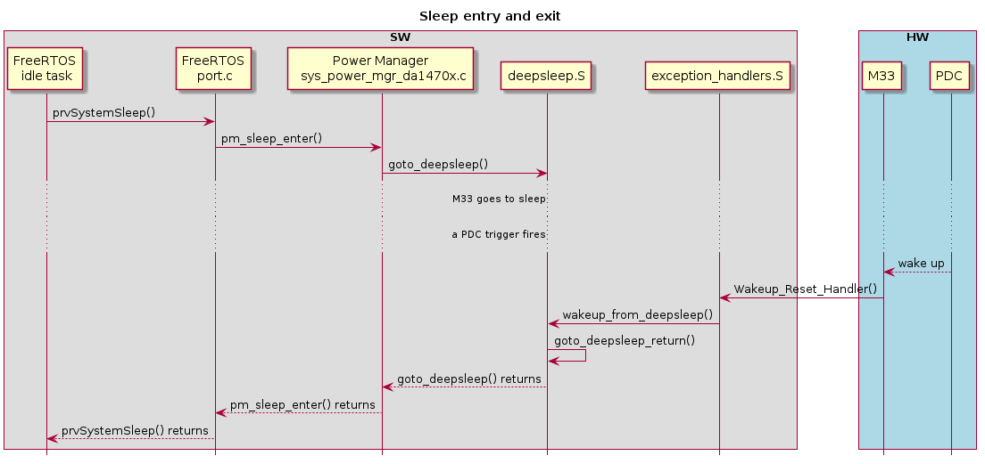
Figure 3 DA1459x system sleep entry and exit
3.4.4. Low level driver
Low level PDC handling is implemented in the hw_pdc Low Level Driver (LLD):
<SDK_ROOT_PATH>/sdk/bsp/peripherals/include/hw_pdc.h<SDK_ROOT_PATH>/sdk/bsp/peripherals/src/hw_pdc.c
The PDC LLD provides preprocessor macros to construct valid PDC LUT entries. See:
HW_PDC_LUT_ENTRY_VAL()generic macro as well asHW_PDC_TRIGGER_FROM_<x>()per trigger source type macros
The PDC LLD provides APIs to:
Read/modify a LUT entry at a given index. See:
hw_pdc_read_entry()hw_pdc_write_entry()
Add/remove a LUT entry taking into account that the LUT may already be populated with some entries. See:
hw_pdc_add_entry()hw_pdc_remove_entry()
Query if PDC LUT entries are pending. See:
hw_pdc_get_pending()hw_pdc_get_pending_cm33()hw_pdc_get_pending_cmac()hw_pdc_get_pending_snc()hw_pdc_is_pending()
Trigger a PDC LUT entry by SW. See:
hw_pdc_set_pending()
Acknowledge a pending PDC LUT entry. See:
hw_pdc_acknowledge()
Control the triggers to a master depending on the FCU status. See:
hw_pdc_set_blocked_triggershw_pdc_get_blocked_triggers
The PDC LLD does not handle system level concerns as:
Concurrent access from different FreeRTOS tasks.
Keeping a master power domain alive while the PDC LUT is being modified. If all entries which keep a master alive get invalidated, its power domain will be immediately turned off terminating its execution.
3.4.5. PDC LLD integration into the system
PDC LUT configuration is applied both:
Statically during startup for setting up entries required by any FreeRTOS BLE application.
Dynamically according to the application’s needs.
PDC LLD is used by the following M33 software modules:
System startup code
Clock manager
Power manager
3.4.5.1. System startup
During startup the PDC lookup table is statically populated with the entries required by all
FreeRTOS BLE applications (see configure_pdc() in sdk/bsp/startup/DA1459x/system_da1459x.c):
Wake up system CPU from
TIMER2(used by FreeRTOS port as the low power timer). Identified asHW_PDC_PERIPH_TRIG_ID_TIMER2in the LLD.Wake up system CPU when signaled from CMAC controller by signal
CMAC2SYS IRQ. Notice that theCMAC2SYS IRQis multiplexed together withdebounced IO IRQandJTAG presentsignal in the same “COMBO” PDC trigger (identified asHW_PDC_PERIPH_TRIG_ID_COMBOin the LLD) so we actually setup a common PDC trigger for all those events.Wake up CMAC controller when signaled by CMAC timer
HW_PDC_PERIPH_TRIG_ID_MAC_TIMER. This is used only in case of a BLE application.
M33 PDC entries are also SW triggered in order PDC to have control on PD_SYS. PDC will keep M33 alive
without forcing PD_SYS to be always on through PMU_CTRL_REG.
3.4.5.2. Clock manager
Upon wake-up or whenever XTAL32M is going to be used as a system clock, clock manager starts XTAL32M by SW-triggering the RTOS timer PDC entry. In case there is no such entry, PDC LUT table is searched for an entry that starts XTAL32M and system CPU. If none is found a new one will be added.
3.4.5.3. Power manager
Power manager checks if the COMBO trigger is pending in order to detect if M33 has been woken-up by
a debugger.
3.4.6. Using PDC in an application
This section describes how to setup a PDC trigger targeting the M33. The example will show how to wake up the M33 from a debounced button press.
First we need to setup the peripheral (Wake-Up Controller) to fire the corresponding interrupt
(debounced IO IRQ - KEY_WKUP_GPIO_IRQ) which will serve as the PDC trigger source. Please refer to Using Wake-Up Controller in an application
for more details on this.
In order to actually wake up the M33 we need to instruct the PDC what to do upon detecting that the trigger has fired. The following code snippet shows how this is accomplished.
uint32_t idx = HW_PDC_INVALID_LUT_INDEX;

idx = hw_pdc_add_entry(HW_PDC_LUT_ENTRY_VAL(
                           HW_PDC_TRIG_SELECT_PERIPHERAL,
                           HW_PDC_PERIPH_TRIG_ID_COMBO,
                           HW_PDC_MASTER_CM33,
                           HW_PDC_LUT_ENTRY_EN_XTAL));
hw_pdc_set_pending(idx);
hw_pdc_acknowledge(idx);
Notice that the “debounced IO IRQ” is multiplexed with other trigger sources (CMAC2SYS IRQ,
JTAG present) in a single PDC peripheral trigger ID (HW_PDC_PERIPH_TRIG_ID_COMBO).
Warning
In the typical FreeRTOS/BLE application you do not actually need to create a PDC
entry for a debounced input IRQ because such an entry should already exist. A COMBO triggered
PDC entry always gets created during system start up in order for the CMAC to be able to wake
up the M33 through CMAC2SYS IRQ.
The constructed PDC entry will wake up M33 (possibly after the “wake up” HW FSM is first triggered
if all masters had previously gone to sleep and the whole device had entered sleep mode) and M33 SW
will see KEY_WKUP_GPIO_IRQ pending in NVIC as soon as M33 starts to execute.
The constructed PDC entry might also request that the 32 MHz crystal oscillator should be started. When this entry gets activated, the PDC will enable the crystal, provided that it has not already been started by any other entry, which required the XTAL32M since the last system wake up (including the entry that triggered the device wake up). The PDC entry will enable the 32 MHz crystal oscillator if the value of the``dg_configENABLE_XTAL32M_ON_WAKEUP`` macro equals to 1.
The above code snippet also triggers by SW the PDC LUT entry and then it acknowledges the pending entry. The former action guarantees that PD_SYS stays on in case the application invalidates all other activated PDC entries which are keeping M33 alive. Acknowledging the newly created (and activated) PDC entry is recommended although not strictly needed since M33 will automatically acknowledge all pending PDC entries before its next attempt to enter sleep mode.
3.5. RTC
Real Time Clock (RTC) is a HW block which provides complete clock and calendar information, generates one-time or recurring alarms and detects when a particular event occurs. For more details please refer to [Ref_01].
The DA1459X SDK provides an extended API with features such as the ability to configure the RTC time and calendar registers, reading the corresponding values, setting alarms, enabling interrupts and setting up the event controller for configuring and enabling the RTC to PDC event.
See also
For more information about the RTC LLD API please refer to the DA1459x SDK Documentation.
3.5.1. Application use
From an application point of view the RTC can be used to track the time and date, utilize the alarm functionality or just the event detection.
3.6. System Clocks
Clocks |
Description |
|---|---|
XTAL32K |
Crystal oscillator for the low power clock (32.786KHz). Crystal tolerance should be up to +/-250ppm. |
XTAL32M |
Crystal oscillator for radio activity and/or DBLR use. Crystal tolerance should be up to +/-20ppm or +/-40ppm untrimmed. |
RCX |
|
RCLP |
|
RC32M |
|
DBLR |
|
3.6.1. Low Power Clocks
During sleep, one of the two low power clocks, RCX or XTAL32K, is used since they have precision of < 500 ppm. The XTAL32K oscillator uses an external crystal resonator, generates 32.768 kHz and it is tolerant of voltage and temperature changes. The enhanced RC oscillator (RCX) is a simple RC oscillator and generates a typical frequency of 15 kHz. The RCX oscillator can be used to replace the 32.768 kHz crystal, since it has a precision of < 500 ppm.
However, RCX is sensitive to temperature changes and requires recalibration. In the case of using the RCX as a sleep clock, the ADC service is enabled that performs periodic temperature measurements and triggers RCX frequency calibration if needed. For more details refer to Section 4.1.4.
The RCLP is also sensitive to temperature changes and requires recalibration. The ADC service is used to monitor the temperature changes and trigger the RCLP frequency calibration if needed. For more details refer to Section 4.1.4.
Note
Only the FCQFN52 package has XTAL32K pins for connecting the external crystal that is required by the XTAL32K oscillator. Thus, only the FCQFN52 package provides both low power clock options (XTAL32K or RCX). In case of the WLCSP39 package, only the RCX option is available.
3.7. Power
Power |
Definition |
|---|---|
DCDC |
Direct Current to Direct Current Converter. |
LDO |
Low Drop Out regulator. Power source during the active or sleep period. |
VBAT |
Battery supply voltage. It is the main power input to the system. |