5. Programming in production
The generated keys, headers, security bits, and application program can be programmed into the DA1459x device during the production process. To do this, the Renesas Production Line Toolkit (PLT) can be used. You can find more information about the PLT on the PLT product page.
This part describes how the generated keys, headers, security bits and application program can be programmed into the DA1459x SOC during the production process.
6. Extracting eFlash content
There are multiple ways of extracting the various parts of the complete binary file needed to program the DA1459x SOC during production. One way is to use the SmartSnippets™ Toolbox, another way is using a program called CLI_Programmer.
6.1. Obtaining the Parts to Program
The goal is to extract the complete application image which has been programmed into the eFlash using the e2 studio.
Warning
When Secure Boot has been enabled, be sure that only the SECURE_BOOT bit is enabled and no other security bits are enabled (see DA1459x Datasheet, chapter 4.6). Else the DA1459x SOC may not be accessible through JTAG- or serial interface.
6.1.1. SmartSnippets™ Toolbox
Below is a description how to extract the complete eFlash content from the DA1459x SOC using the SmartSnippets™ Toolbox. The SmartSnippets™ Toolbox can be downloaded from SmartBond Development Tools.
Connect your board to your computer, either through serial (UART) or JTAG (SWD) interface.
Open SmartSnippets™ Toolbox and Select the DA1459x SOC Board:
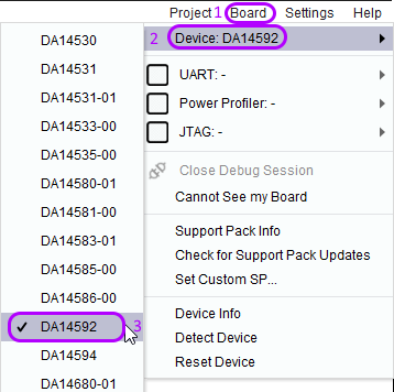
Figure 13 Select DA1459x SOC Board
Select Board (again) and select either JTAG and/or UART interface (depends on your interface connection to your application):
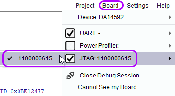
Figure 14 Select interface
Select Programmer and Flash Code to open the (e)Flash Window:
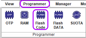
Figure 15 Select Flash Code Programmer
The following window will appear:
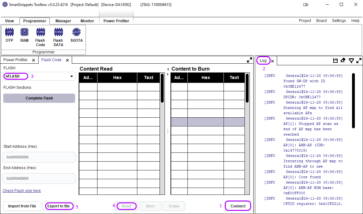
Figure 16 eFlash Window
Press the Connect button (1) to start the communication between your board and SmartSnippets™ Toolbox. After a couple of seconds the communication is established (Please check the Log window (2) for errors).
Select eFlash (3) and press the Read button (4). A window will pop-up asking if you want to read 264192 bytes. Press the Yes button to read the complete eFlash content. When reading is finished the Content Read will be populated:
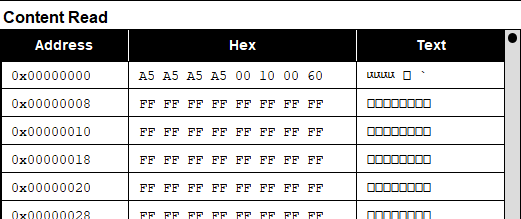
Figure 17 eFlash Content
Double check that the first 4 bytes read A5A5A5A5. After checking the correctness of the first 4 bytes press Export to file (5). Fill out the pop-up window and press Ok:
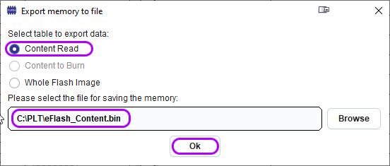
Figure 18 Export memory to file
Now you should have a copy of the eFlash content on your computer.
Note
If the image you retrieved from the eFlash has Secure Boot enabled you should read further in chapter Image Sections
6.1.2. CLI_Programmer
Below is a description how to extract the complete eFlash content from the DA1459x SOC using the CLI_Programmer software.
The CLI_Programmer is part of the SDK software and can be found in SDK/binaries.
6.1.2.1. Serial (UART) connection
Connect your board to your computer with a serial (2-wire) cable.
Open your computer’s Device Manager (Windows) and locate the COM-port your application is connected to:
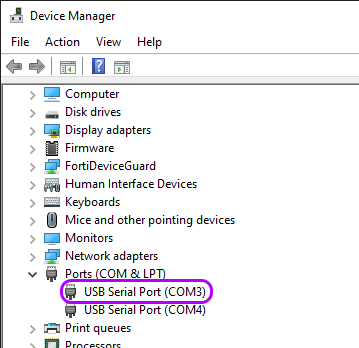
Figure 19 Com port
- Go to your ../SDK/binaries directory and enter the following command:
cli_programmer -b uartboot.bin COMxx read_eflash 0x0 flash_content.bin 0x40000
Press ENTER (You may be asked to reset your board).
This will copy the eFlash content to the flash_content.bin file.
Double check with a HEX editor/reader that the first 4 bytes read A5A5A5A5.
6.1.2.2. JTAG (SWD) connection
Connect your board to your computer through a Segger J-Link probe.
Start the J-Link GDB server by executing
JLinkGDBServer.exefound in c:\Program Files (x86)\SEGGER\JLink_Vxxx\. The following window will pop-up: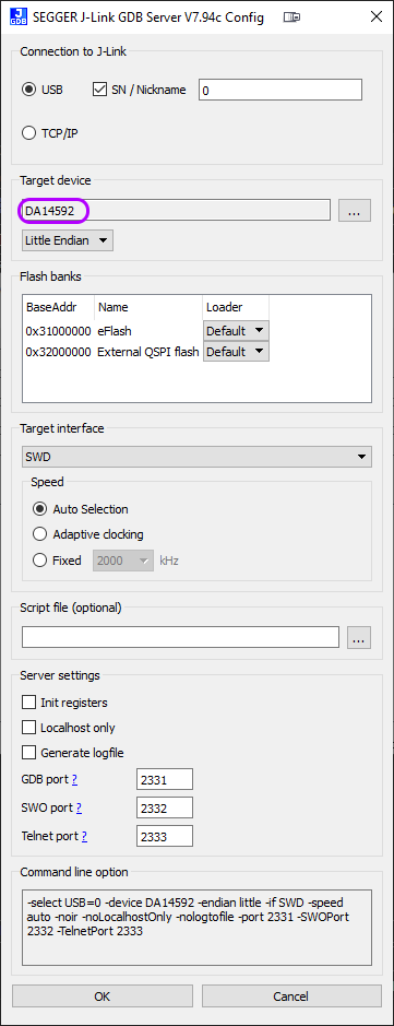
Figure 20 GDB server
Select the Target device (DA14592 or DA14594) and press OK
- Go to your ../SDK/binaries directory and enter the following command:
cli_programmer -b uartboot.bin gdbserver read_eflash 0x0 flash_content.bin 0x40000
Press ENTER
This will copy the eFlash content to the flash_content.bin file.
Double check with a Hex editor/reader that the first 4 bytes read A5A5A5A5:

Figure 21 First 4 bytes
6.2. Image Sections
When the binary file is programmed using Secure Boot a couple of extras have been programmed in the Configuration Script, Product Header and Image Header.
6.2.1. Configuration Script and Key Area
The configuration script and key area have the following lay-out:
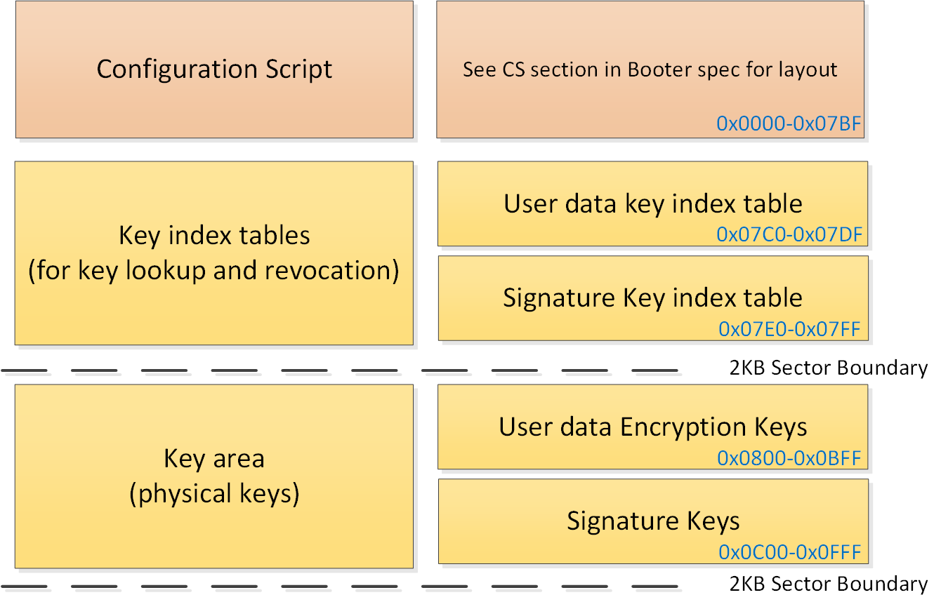
Figure 22 Configuration Script / Key Area
A valid configuration script always starts with A5A5A5A5:

Figure 23 Configuration Parts
The 2nd 32-bit word (0x60001000) tells the booter where the Flash Product Header is located, in this case : 0x1000. (See also DA1459x Datasheet, Chapter 4.6).
The 3rd 32-bit word (0xC0000080) is the Set-Once Bits Configuration to program the set-once (sticky) bits for hardware configuration and security features. (Since this word is security related it’s repeated in the 4th 32-bit word).
Since only the SECURE_BOOT bit (7) has been programmed, the LSB = 0x80:
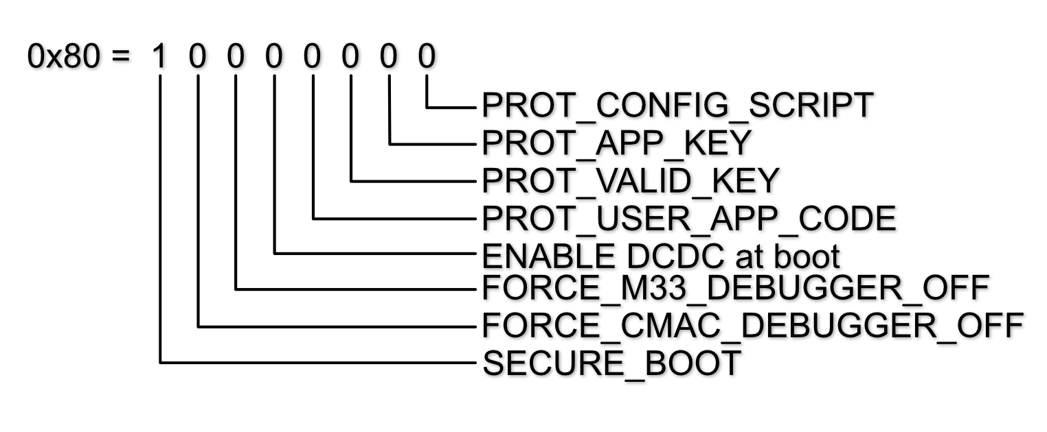
Figure 24 Sticky Bits
6.2.2. Key Index Tables
At the end of the first flash sector there are 2 key index tables consisting of 16 32-bit words. 8 Words representing 8 User Data Key Indexes (starting at address 0x07C0):

Figure 25 User Data Key Index Table
And 8 words representing 8 Signature Key Indexes (starting at address 0x07E0):

Figure 26 Signature Key Index Table
6.2.2.1. Key invalidation
When one or more key(s) are invalidated, the secure_cfg.xml file located in ..\utilities\python_scripts\secure_image\ is updated with a pointer to the new key and index number of the invalidated key(s):
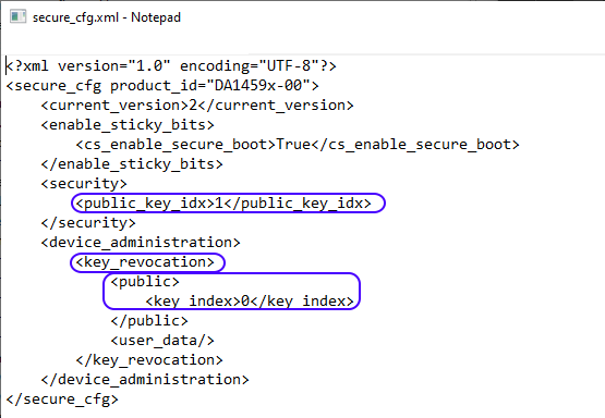
Figure 27 secure_cfg.xml
For every key that is invalidated (when initially programmed or by updating the software over the air (SUOTA)), the corresponding 32-bit word in the key index table is set to 0x00000000.
The next example shows an invalidation of the 1st signature key:

Figure 28 Invalidated Signature Key
6.2.3. Key Area
The generated keys are stored in the product_keys.xml file located in ..\utilities\python_scripts\secure_image\ :
<?xml version="1.0" encoding="UTF-8"?>
<keys>
   <symmetric>
      <!--User Data Encryption Keys-->
      <symmetric_key>D6770BDBF47B246033949325EF80AC7B43BE876E1F4EB1A69AB8218B894F6EAD</symmetric_key>
      <symmetric_key>50B73F62F8A502B182E6E16E7BA3F1A7D1E3AD3FE551A4D9E1406EF74CECE463</symmetric_key>
      <symmetric_key>DC0291CF8B6363B8EC25A690C0DB331BC517E51ACE2D4D271839A7E0DC630C47</symmetric_key>
      <symmetric_key>2161E969D43EAF3E1A5ACCD1E5B3DBA0C662174602691657E7ABB48C603C4D20</symmetric_key>
      <symmetric_key>C8DB2F79FCBD4E0BB48D3A7A13B04FFE7CCD2B0CA88D6633F59F7D4401000EB5</symmetric_key>
      <symmetric_key>78794B472A69A9E761C4D8D2715CF8FD905F0AB4E821A481EB1CE94FE736B9CF</symmetric_key>
      <symmetric_key>DA42251B87C8269AC9098E23283E3E65AA219A86EBAE3A0A702BE2F73966B536</symmetric_key>
      <symmetric_key>953EA53D3B642EEB956344B35FDE8AFD7119C4C9D9BC8F962DD3508220186AB2</symmetric_key>
   </symmetric>
   <asymmetric>
      <!--Signature Keys-->
      <asymmetric_keys>
            <private>166004C0057941B1798C01C7751A11A8DA11F6D9E8438CD40217ED5BB17E940B</private>
            <public>5EC62C78E4A3D1C3CC25C76E686BCDA7196B10EAB14EEEE18CBDEA345F1DCB05</public>
            <elliptic_curve>EDWARDS25519</elliptic_curve>
      </asymmetric_keys>
      <asymmetric_keys>
            <private>DE98ADD4994F10555B7499106BC856E9E77A0CA6519AD8024AD012FC9C4E7675</private>
            <public>6EA6CFD35589838FD2D01888615A83D195FC71D59FCC4303AF6424CD19661E19</public>
            <elliptic_curve>EDWARDS25519</elliptic_curve>
      </asymmetric_keys>
      <asymmetric_keys>
            <private>E60F96286C651E3A7E9C7099A1B6DB6A342263B4F931636FD1C977DEC75D981F</private>
            <public>9B6185359E226421E9CBEBCFEDB24F4D247FC569455403A1C4A0B7DE7E483050</public>
            <elliptic_curve>EDWARDS25519</elliptic_curve>
      </asymmetric_keys>
      <asymmetric_keys>
            <private>2EC7C0BC80BA6D5EE104886117E5A02BC20BF901E1072F1C99021B0032ACFA09</private>
            <public>1D97EE7190160A3BCE7EDD63B81C6F33CFA8DF5F48D16FCB34DF969DC66B78B5</public>
            <elliptic_curve>EDWARDS25519</elliptic_curve>
      </asymmetric_keys>
      <asymmetric_keys>
            <private>B6BE2991D350FBC383ACE06ACC53A52C8F33CF8E0A1E3A0AA07B0062DD3C9C33</private>
            <public>7A9B15A1D99855F19D148C65AE6ADB153D9AF7FCE1F573AA1BC5B9B583984821</public>
            <elliptic_curve>EDWARDS25519</elliptic_curve>
      </asymmetric_keys>
      <asymmetric_keys>
            <private>7EF6D2A56626CA67669478B3C201EA6D9C9CE55B72758637E8342503C80B7E9D</private>
            <public>6ED326735AD2CDAC561B665FDCB8FF8D288F74DEF17D4ED1F47910582EF456B7</public>
            <elliptic_curve>EDWARDS25519</elliptic_curve>
      </asymmetric_keys>
      <asymmetric_keys>
            <private>876DBCF93A3CD84B89BC4F3BF8F06FEEE9443C681A0C11A5702D8AE5F31AA047</private>
            <public>29C1070265E3800FE0EA975AE63D749D0B2E3D33906D24AC8D854A7469BEA0B5</public>
            <elliptic_curve>EDWARDS25519</elliptic_curve>
      </asymmetric_keys>
      <asymmetric_keys>
            <private>CF25E58D4D922770EB2467046E1E34AF762DD2B603E3DD5237662E075E6A0331</private>
            <public>01EC484EC6904EF6144FC1711AD46884C9474A8D03040BD5BD2BB1EEFECACA0E</public>
            <elliptic_curve>EDWARDS25519</elliptic_curve>
      </asymmetric_keys>
   </asymmetric>
</keys>
The User Data Encryption Keys (symmetric) are stored in eFlash starting at address 0x0800:
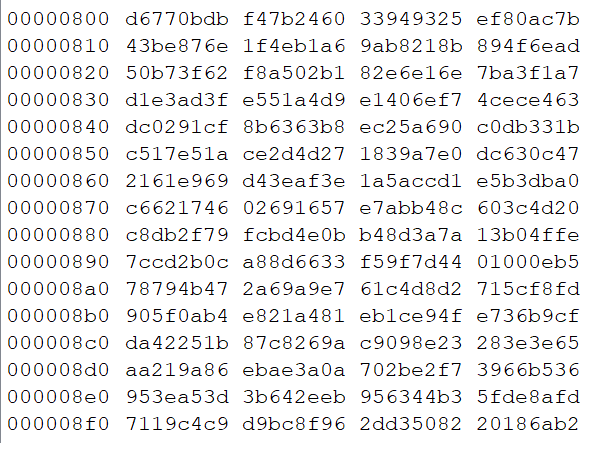
Figure 29 Symmetric Key Area
The Public signature keys are stored in eFlash starting at address 0x0C00:
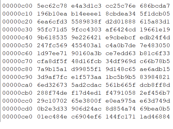
Figure 30 Signature Key Area
6.2.4. Product Header
The next eFlash sector, starting at 0x1000 is the product header:
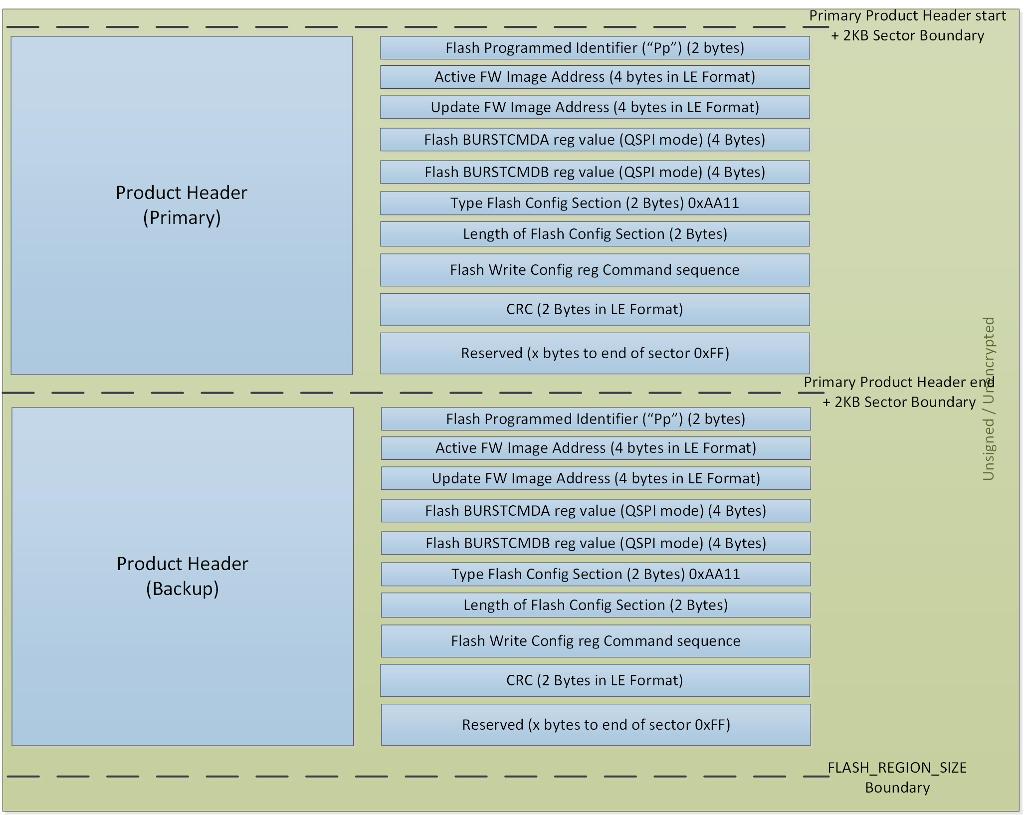
Figure 31 Product Header Layout
Besides the primary Product Header there is also a Back-up version, starting at address 0x1800. This back-up is for save-keeping in case the primary Product Header gets corrupted.
The first 2 bytes are identifiers (“Pp”), indicating that the eFlash is programmed.
The next 4 bytes is the address where the Active Firmware Image starts. In case of a single image the Active Image starts at address 0x2000.
The next 4 bytes is the address where (a possible) Update Firmware Image starts. When the device is initially programmed there is only 1 Firmware Image and therefore this address is the same as the Active Firmware Image (0x2000).
The next 8 bytes contain the BURSTCMDA & BURSTCMDB value needed for the QSPI controller (not applicable for the eFlash).
Next bytes are the Flash Config Section Identifier (= 0xAA11) and the length of the Flash Config Section. The following bytes are the command sequence to set the (QSPI)Flash in QUAD SPI mode. And finally the CRC check.
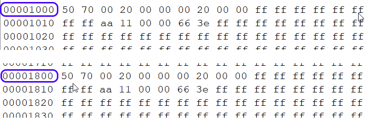
Figure 32 Product Header
6.2.5. Image Header
The next eFlash sector, starting at 0x2000 is the image header.
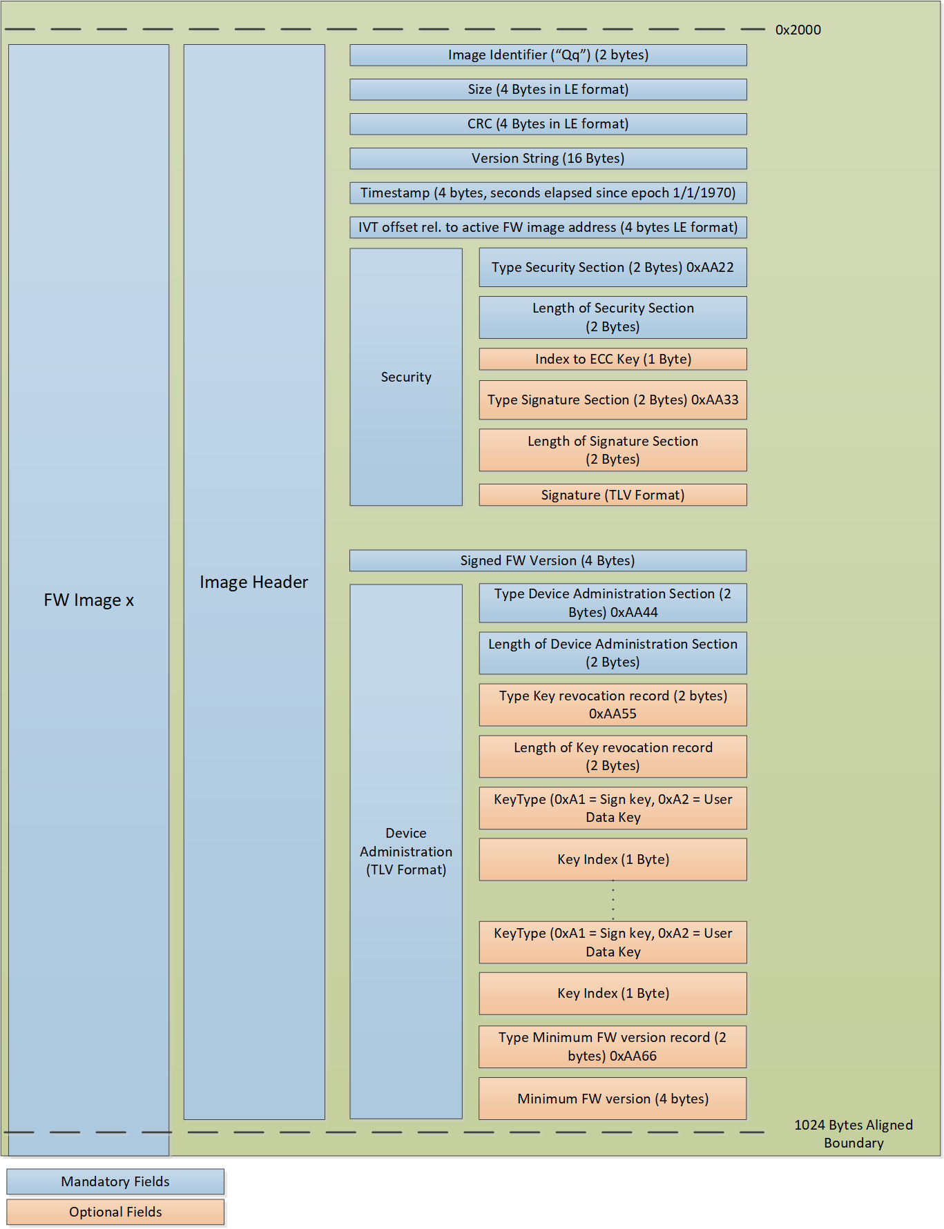
Figure 33 Image Header Layout
The first 2 bytes are identifiers (“Qq”), indicating the start of the image header.
The next 4 bytes is the size of the Application Image (starting at the Interrupt Vector Table (0x2400)).
The next 4 bytes is the calculated CRC of the Application Image.
The next 16 bytes is the (ASCII) version string.
Following 4 bytes is the timestamp (seconds elapsed since epoch 1/1/1970).
Following 4 bytes is the Interrupt Vector Table relative offset to the start of the Active Firmware Image.
The next 2 bytes is the Security Section Identifier (= 0xAA22).
Followed by the length of the Security Section (2 bytes).
The next byte is the index number of the signature key in the signature key index table.
The next 2 bytes is the Signature Section Identifier (= 0xAA33).
Followed by the length of the Signature Section.
And finally the Signature and the Firmware Version.
The last part of the Image Header is the Administration Section which is used to keep an administration of revoked keys (if any) and minimal Firmware Version (if any):
0xAA44 Administration Section Identifier.
Length of the Administration Section (2 bytes).
0xAA55 Key revocation Section Identifier.
Length of the Key Revocation record size (2 bytes).
Key type of the key (eg. Signature key (oxA1) or Use Data Key (0xA2)).
Key Index
Next Key Records (if more Keys are revoked).
0xAA66 Minimum Version Identifier.
Minimum Firmware Version (4 bytes).
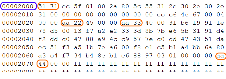
Figure 34 Image Header
Note
Not all sections might be populated, depending on settings for Secure Boot, Key revocation and minimal Firmware Version
6.2.6. Application
The last section is the Application Executable starting with the Interrupt Vector Table (IVT):

Figure 35 Application Executable