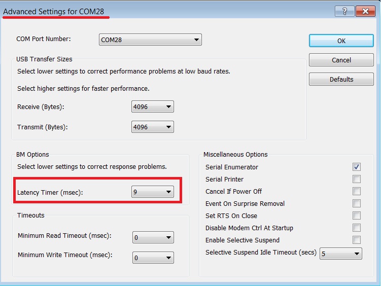
When using an external FTDI cable for OTP burning or image downloading to external memory, it is important to set the FTDI cable’s latency timer to less than 10 ms.
Complete the steps below to change the latency timer:
Open the Windows Device Manager.
In the Device Manager, expand the list of COM ports.
Right-click on the COM port relevant to your setup and select Properties.
In the Port Settings tab, click Advanced.
Set the Latency Timer to a value less than 10 ms.
Click OK to save the changes and then close the Device Manager.
Hint
You can find a visual reference for the “FTDI Latency Timer” in Figure 40.
You can burn data into the SPI flash using SST (SPI Serial Transfer) over a single UART connection. However, there are specific pin configurations you need to follow for this setup. When programming the SPI flash using 2-wire UART, you need to perform OTP (One-Time Programmable) programming. This is because the default SPI pins are shared with the default UART pins (P0_0/P0_1).
For detailed information on how to configure the pins and perform this process, see Section 8.3 in the AN-B-072.
Use of the Single Wire UART to Download Code in SPI Flash is also possible. The figure below shows the default configuration on Prodevkit and SmartSnippets™ Toolbox:
Figure 44 SPI flash programing through UART: Pin configuration
Renesas SmartSnippets™ Studio is a royalty-free software development
platform for Smartbond™ devices. It fully supports the DA1453x family of devices. For the SmartSnippets™ Package, you need to install only SmartSnippets™ Studio.
SmartSnippets™ Toolbox is a comprehensive software development tool that covers various development requirements:
Firmware Management:
- SmartSnippets™ Toolbox enables programming and loading firmware into various memory types, including SRAM, OTP, EEPROM, and Flash.
Power Profiling:
- It offers power profiling capabilities, allowing you to assess and optimize power consumption for your applications.
Terminal Scripting:
- SmartSnippets™ Toolbox provides features for terminal scripting, simplifying interactions with your device and streamlining debugging.
Documentation:
- Extensive SmartSnippets™ Toolbox documentation is available to assist you in making the most of this powerful development tool.
SmartSnippets™ Toolbox is an indispensable resource for your software development needs.
SmartSnippets™ Installation
These are the steps to install:
Download the latest version of SmartSnippets™ Studio from Development Tools.
Note: Registration is required in order to download the SmartSnippets.
Warning
Beaware that if you have antivirus software installed on your machine, it could slow down the SmartSnippets™ installation due to the scan.
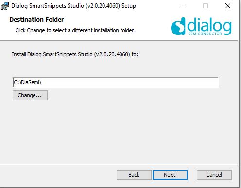
Run the SmartSnippets™ Studio installer (.msi). Most of the required tools are automatically installed andm some needs to be manually downloaded and installed.
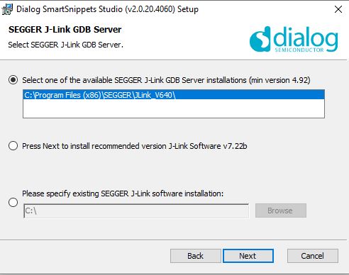
Select the latest version of SEGGER J-Link GDB Server and click Next.