5. Testing the code
The code can be tested by using 2 10k ohm resistors connected to the NTC connection pins P1_0, P0_7 and ground:
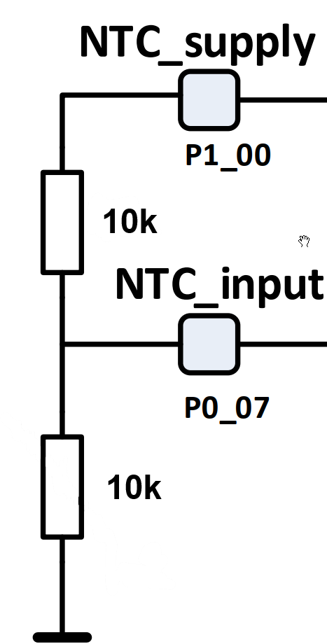
Fig. 5 Test resistors
Steps:
- The compiled software can be loaded onto the target using the SmartSnippets Studio debugger. Once the software is loaded and started to run, the (HCI) test command can be send to the target using a terminal program like Realterm.
- Start the terminal program @ 115k, 8/N and connect to the target boards com port:
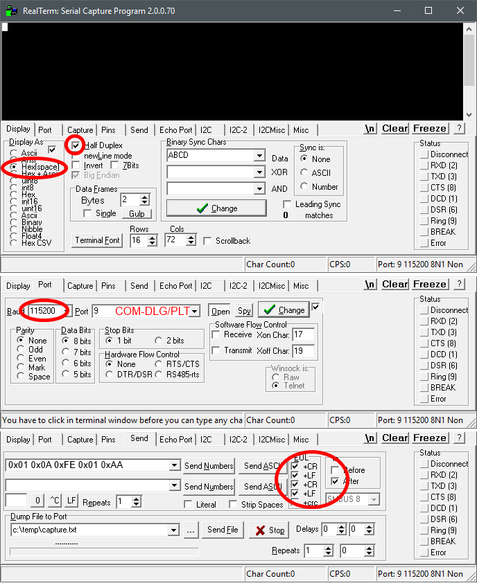
Fig. 6 Terminal (Realterm)
- The (test) command bytes are 0x01 0x0A 0xFE 0x01 0xAA, where 0xAA is the command ID for the specific NTC test.
- Enter these bytes in the ‘Send’ tab and press the button Send Numbers.
- If the resistor network is connected correctly, the return message will end with AA which means passed. If 00 is returned, there is a connection failure; either a resistor is not connected or completely missing.
- By changing the command ID (AA) in the test command, any other implemented custom test can be tested this way.