4. NTC custom code
4.1. Code Implementation
The first part is a check if P0_07 is connected to R1//NTC. If P0_07 is not connected and left floating, it is possible that the 2 comparators are in a state indicating that R1 and NTC are connected correctly (which they are not). Therefore, P0_07 is put as GPIO-high and P1_00 is put as GPIO input, to check the (high) state of P0_07. If P0_07 is not connected (or R1 is missing/not connected), a false is reported and the case exits.
In the second part, P1_00 is put as GPIO-high to feed the R1/NTC network and P0_07 is put as GPIO input. By enabling the charger and the charger clock, the TBAT reference ladder network and the 2 comparators are enbaled (see Fig.2). By reading the state of the 2 comparators in the [CHARGER_STATUS_REGISTER], a check can be made if R1 and NTC are connected (or not) or short-circuited.
The implementation in the hci_custom_action() function is as follows:
void hci_custom_action(dgtl_msg_t *msg)
{
      plt_cmd_hci_custom_action_t *cmd = (plt_cmd_hci_custom_action_t *) msg;
      dgtl_msg_t *msg_evt;
      plt_evt_hci_custom_action_t *evt;

      msg_evt = init_response_evt(&cmd->hci_cmd, sizeof(*evt));
      evt = (plt_evt_hci_custom_action_t *) msg_evt;

      switch(cmd->custom_action)
      {
         case (0xAA):
                  hw_gpio_pad_latch_enable(HW_GPIO_PORT_0, HW_GPIO_PIN_7);
                  hw_gpio_configure_pin_power(HW_GPIO_PORT_0, HW_GPIO_PIN_7, HW_GPIO_POWER_V33);
                  hw_gpio_configure_pin(HW_GPIO_PORT_0, HW_GPIO_PIN_7, HW_GPIO_MODE_OUTPUT,
                          HW_GPIO_FUNC_GPIO, true);
                  hw_gpio_set_pin_function(HW_GPIO_PORT_1, HW_GPIO_PIN_0, HW_GPIO_MODE_INPUT_PULLDOWN,
                          HW_GPIO_FUNC_GPIO);
                  hw_gpio_pad_latch_disable(HW_GPIO_PORT_0, HW_GPIO_PIN_7);

                  if (!hw_gpio_get_pin_status(HW_GPIO_PORT_1, HW_GPIO_PIN_0))     /* Check P0_7 - P1_0 resistor & NTC connection */
                  {
                          evt->custom_action = 0;
                          break;
                  }

                  hw_charger_set_clock_mode(true);                                /* Enable charger FSM */
                  hw_charger_set_analog_circuitry_operating_mode(true);
                  hw_gpio_configure_pin_power(HW_GPIO_PORT_1, HW_GPIO_PIN_0, HW_GPIO_POWER_V33);

                  /* ReConfigure the pins. */
                  hw_gpio_pad_latch_enable(HW_GPIO_PORT_0, HW_GPIO_PIN_7);
                  hw_gpio_set_pin_function(HW_GPIO_PORT_0, HW_GPIO_PIN_7, HW_GPIO_MODE_INPUT, HW_GPIO_FUNC_GPIO);
                  hw_gpio_pad_latch_enable(HW_GPIO_PORT_1, HW_GPIO_PIN_0);
                  hw_gpio_configure_pin(HW_GPIO_PORT_1, HW_GPIO_PIN_0, HW_GPIO_MODE_OUTPUT, HW_GPIO_FUNC_GPIO, true);
                  hw_gpio_pad_latch_disable(HW_GPIO_PORT_1, HW_GPIO_PIN_0);
                  hw_gpio_pad_latch_disable(HW_GPIO_PORT_0, HW_GPIO_PIN_7);
                  hw_clk_delay_usec(1000);
                  char tbat_main = REG_GETF(CHARGER, CHARGER_STATUS_REG, MAIN_TBAT_COMP_OUT);
                  char tbat_hot = REG_GETF(CHARGER, CHARGER_STATUS_REG, TBAT_HOT_COMP_OUT);       /* Check charger comparator status */
                  if (tbat_main & !tbat_hot)
                  {
                          evt->custom_action = cmd->custom_action;
                  }
                  else
                  {
                          evt->custom_action = 0;
                  }
                  hw_charger_set_clock_mode(false);                                /* Disable charger FSM */
                  hw_charger_set_analog_circuitry_operating_mode(false);
                  hw_gpio_set_pin_function(HW_GPIO_PORT_1, HW_GPIO_PIN_0, HW_GPIO_MODE_INPUT, HW_GPIO_FUNC_GPIO); /* Reset pin to input */
                  break;
            default:
            {
                    evt->custom_action = cmd->custom_action;
                    break;
            }
      }
      dgtl_send(msg_evt);
}
4.2. Code Integration
In order to integrate the custom (NTC) code in the PLT firmware the following steps need to be taken:
- As described in the Getting started, download and instal the latest SmartSnippets Studio and the latest SDK.
- In the following steps, a couple of changes will be made to the SDK and it is therefore advisable to start with a clean installation and not mix up with a regular application.
- In the PLT software there is a directory called SDK_10.0.8.105. Copy all the files in the SDK_10.0.8.105 subdirectory over the original SDK.
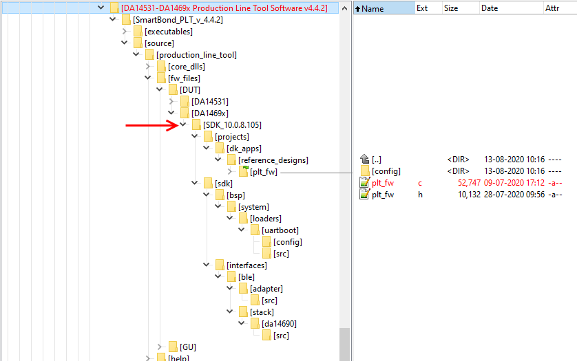
Fig. 4 PLT firmware tree
- In the subdirectory SDK_10.0.8.105->projects->dk_apps->reference_designs->plt_fw, there is the file plt_fw.c with the original hci_custom_action() function. Copy and paste the new hci_custom_action() function (see Code 3 above) over the original function.
- There are 2 new functions in Code 3 which needs to be declared in the same plt_fw.c file:
hw_charger_set_clock_mode()
hw_charger_set_analog_circuitry_operating_mode()
- Add the following 2 functions just before the function static bool plt_check_gpio() (at line 155)
__STATIC_INLINE void hw_charger_set_clock_mode(bool mode)
{
        GLOBAL_INT_DISABLE();
        REG_SETF(CRG_SYS, CLK_SYS_REG , CLK_CHG_EN, mode);     /* Enable/Disable charger clock */
        GLOBAL_INT_RESTORE();
}

__STATIC_INLINE void hw_charger_set_analog_circuitry_operating_mode(bool mode)
{
        REG_SETF(CHARGER, CHARGER_CTRL_REG, CHARGER_ENABLE, mode); /* Enable/Disable charger block */
}
- Compile the code for RAM execution.