10. Running the Demo
This project can demonstrate the word recognition functionality using two methods:
The first will make use of the LEDs on the daughterboard.
The second will make use of an LCD mounted on the motherboard.
In both cases the same debug messages will be printed through the serial port.
10.1. Build configurations
To switch between these two modes the user needs to build the project with different configurations. These are shown in the figure below.
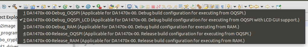
Figure 16 Project build configurations
Number 1 will make use of the LEDs and number 2 the LCD display. Download the build firmware file using the steps already mentioned in section Setting up the workspace.
Note
Since the demo is working with a 160MHz clock the user needs to change manually the LCD write frequency in the following path: ui/dgi/inc/e120a390qsr.h (.hw_init.write_freq = LCDC_FREQ_40MHz,)
10.2. Serial port setup
When connecting a DA1470x DevKit to a host PC, two sequentially serial ports become available. The COM port with the lowest value is the one that the log messages are propagated. E.g. if COM8 and COM9 become available, COM8 will be used.
Open a serial terminal emulator.
Configure and create a new serial connection, to the COM port with the lowest number, using the following parameters.
Port Parameter |
Port Value |
|---|---|
Baud rate |
921600 |
Parity |
None |
Data |
8 |
Stop Bit |
1 |
Flow control |
None |
10.3. User experience
By pressing the reset button, the program execution begins. The DA1470x will go immediately to sleep until a VAD interrupt wakes the system up. The following figure presents the project functionality on wakeup.
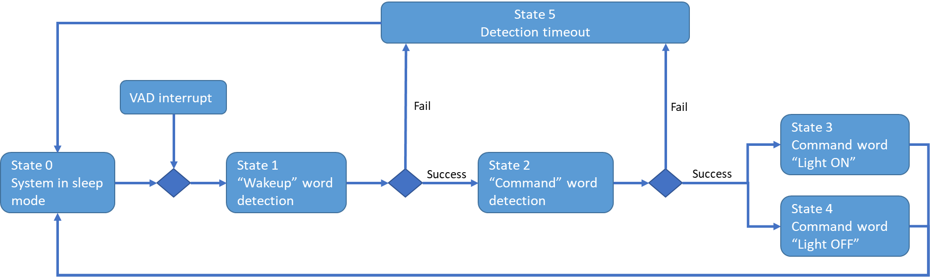
Figure 17 Word detection flow chart
10.3.1. Serial port user experience
On startup, the serial port will print out DSpotter model information as mentioned in section Update the project with a new Model.
State 1: The serial will output repeatedly a dot symbol to indicate detection is taking place.
State 1-Success: The serial will print out the word that was detected from model in group 0 along with library information concerning the success rate.
State 2: Similarly, with State 1, the serial will output repeatedly a dot symbol to indicate detection is taking place.
State 2- Success: The serial will print out the word that was detected from the model along with library information concerning the success rate.
State 1 & 2-Fail: the serial port will print out a timeout message indicating that the recognition process has terminated.
State 3 & 4: Will simply print out the successful result from State 2 which is either “Lights ON” or “Lights OFF” .
A full cycle of Serial port messages is shown below:
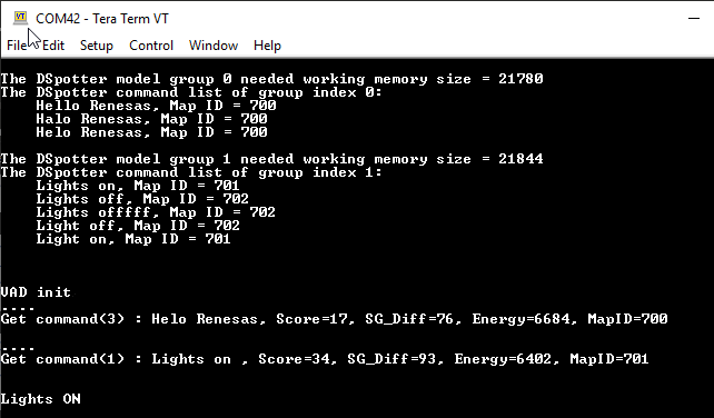
Figure 18 Serial port user experience
10.3.2. User LED functionality
The LEDs are also used to demonstrate some of the states described in the above figure.
State 1: A green LED will toggle with 300ms period indicating “wake-up word” detection is taking place.
State 1-Success: The green LED will switch to a faster toggle rate (~60ms), to indicate detection was successful on “wake-up” word and now “command word” detection is taking place.
State 3: Green LED will illuminate for 1sec. Command word “Lights ON” was successfully recognized.
State 4: Blue LED will illuminate for 1sec. Command word “Lights OFF” was successfully recognized.
State 5: A red LED will illuminate for 1sec. Timeout has occurred.
10.3.3. LCD user display
Another option provided from the application is to use the LCD. Less information on the detection process will be presented to the user.

Figure 19 LCD user display
State 0 & 1: On reset the left image is displayed.
State 1-Success: (Image on the middle) In this state the user is informed that detection was successful for “wake-up” word and now the library is waiting for the “command word.
State 3 & 4: Following a successful “command word” recognition the LCD will display either the left (Light bulb turned OFF) or right (Light bulb turned ON) image.
The LCD will never go blank, a light bulb image will always be displayed. The image can alternate between ON and OFF only if a valid “command word” is detected.