8. VAD block
VAD is based on WT (Whisper Trigger) from Dolphin, a mixed analog/digital Virtual Component (ViC). More information is available on the official site of Dolphin Design
8.1. Voice detection principle
The VAD system relies on the principle of energy-based detection. VAD computes both the short-term energy (for voice signal) and the long-term energy (for ambient noise) in the voice bandwith ([100Hz-6kHz]). The detection of a voice event occurs when the relative power between the short-term energy and the long-term energy exceeds a programmable threshold (Power Level Sensitivity).
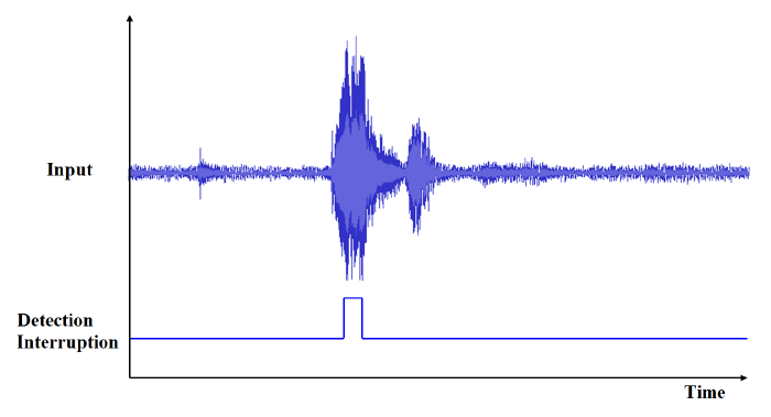
Figure 2 Voice detection principle
8.2. Reference application schematic
The VAD block and the PGA/AppADC are connected in parallel to an external analogue microphone. The microphone must be constantly powered for the VAD to wake up the CPU when a significant amount of audio energy is detected. The PGA/AppADC is powered on and starts fetching samples into RAM for further processing.

Figure 3 Reference application schematic
The VAD and analog microphone (AMIC) are supplied with 3 V by the V30 power rail of the chip. The PGA and the AppADC are supplied with 1.8 V by the V18P rail of the chip.
8.3. VAD operation modes
This unit has 3 possible operation modes as shown in VAD operation modes.
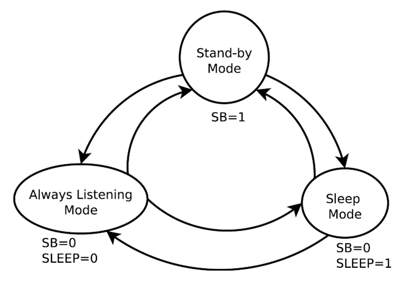
Figure 4 VAD operation modes
Stand-by:
VAD is turned off. No voice event can be Detected. Set this mode to get maximum power saving.
Sleep:
VAD analog part is powered on. No voice event can be detected. ” Sleep” mode allows a fast transition to Always Listening mode. This is the preferred mode of operation while recording audio using the AppADC.
Always Listening:
VAD is fully powered on. Interrupts are generated for detected voice events.
Note
It is recommended to change the sensitivity settings while the device is in its Stand-by or Sleep mode. See the register description below.
8.4. Device registers and parameters
Five Internal registers are responsible for the operation and behavior of the VAD unit as shown in Table 1. These registers are described in detail in the DA1470x manual, “§44.32 Voice Activation Detection Controller Registers”.
Register name |
Function |
Address |
Reset value |
|---|---|---|---|
CR0 |
Control Register 0 |
0x00 |
0x64 |
CR1 |
Control Register 1 |
0x01 |
0x02 |
CR2 |
Control Register 2 |
0x02 |
0x27 |
CR3 |
Control Register 3 |
0x03 |
0xC0 |
CR4 |
Control Register 4 |
0x04 |
0x64 |
Parameters that are responsible for the HW setup of the system are located through registers CR3-CR4. The rest affect the actual energy-based detection and will be described below:
VTRACK (Voice Tracking). This parameter allows to set the adaptation speed of the system depending on the voice input. When the setting of this parameter is low, the high-frequency sensitivity of the VAD increases, some phonemes can be detected easily but high-frequency ambient noise can be mistaken as voice. When the setting of this parameter is high, the high-frequency sensitivity of the VAD decreases, high frequency ambient noise is filtered but some phonemes can be lost.
NTRACK (Background Noise). This parameter allows to set the speed of the system adaptation to the ambient noise. This parameter gives the flexibility to adapt the VAD to the application environment.
PWR (Power Level Sensitivity). Ratio between ambient noise and voice level to be detected. Detection of a voice event occurs when relative power between the short-term energy and the long-term energy exceeds a programmable threshold.
MINDELAY (Minimum Delay). This parameter allows to set the minimum time before a detection when switching to Always listening mode.
MINEVENT (Minimum Event Duration). This parameter allows to set the Minimum vocal signal duration that can be detected by the system. When the setting of this parameter is low, the detection latency decreases but the high-frequency ambient noise can be considered as voice. When the setting of this parameter is high, the high-frequency ambient noise is filtered but the detection latency increases. This delay is defined as the number of clock cycles.
Noise Floor Information (NFI). This register presents the ambient noise reference level used in the VAD. The NFI represents the average during typically 100 ms of the peak output noise level, given in dBVp on the audio bandwidth [20 Hz-20 kHz] after a [100 Hz-6 kHz] first order filtering.
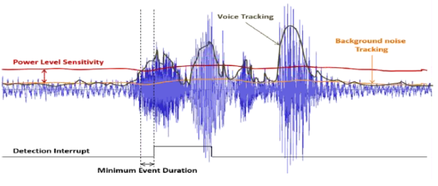
Figure 5 VAD detection related parameters
8.5. VAD Application Example
This application demonstrates a complete solution for the VAD engine. This includes the following sections:
Basic VAD setup and operation.
Cyberon DSpotter library for voice recognition applications.
An LCD to present voice command results.
All related code is presented to help the reader understand the functionality of the VAD unit and setup the behavior according to the user application requirements.
This chapter refers only to VAD unit, the DSpotter solution will be described into chapter DSpotter. The LCD is described in a separate application note.
The application example is located in the follwing GitHub link:
https://github.com/dialog-semiconductor/BLE_SDK10_DA1470x_examples
“vad_keyword_detection” example can be found inside the “features/vad_demo_lvgl/” folder.
8.5.1. Setting up the workspace
SmartSnippets Studio is used to build the projects needed for this demo. The version currently in use is the 2.0.18.4016. First dialog screen will request a valid directory where the SDK is extracted as shown in the below figure.
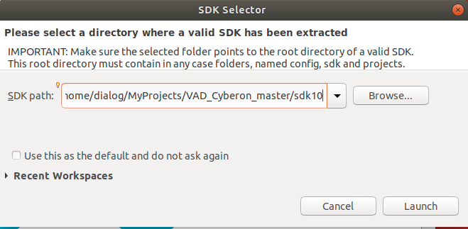
Figure 6 SmartSnippets selecting SDK directory
In the welcome screen, select the Eclipse/GCC IDE icon. Project explorer tab should be empty, the user must import the projects that are needed for this demo by clicking the appropriate message shown in figure below.
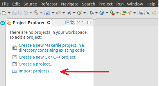
Figure 7 Importing demo projects
In the Import dialog, “Existing Projects into Workspace” must be selected. The following dialog requires to choose the exact projects that are needed for this demo. It is important that the root directory points to a valid path of the SDK. If this path is incorrect or not specified, the ” Projects” list will not be populated.
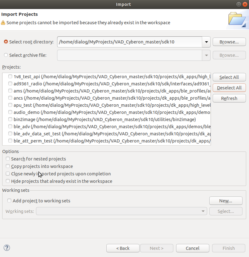
Figure 8 SDK projects list
The projects that must be added for this example are shown in the below figure, this should also be the final form for the Projects tab:
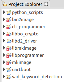
Figure 9 VAD demo project resources
To build please use the target configuration DA1470x-00-Debug_OQSPI. In the “periph_setup.h” file undefine ENABLE_DSPOTTER_LIB to exclude the voice recognition functionality for this section.
To build the project, “vad_keyword_detection” must be selected and Project->”Build All” needs to be executed for the first time. Having successfully built the solution, it is time to download the application to the hardware. For this action use “External Tools”.
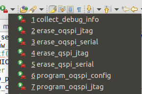
Figure 10 External Tools
Make sure the motherboard DK is connected to the PC via a USB cable. From “External Tools” configure the oqspi for the first time. The configuration might vary depending on the flash used on the daughterboard. A configuration example is presented in the figure below.
Figure 11 OQSPI Configuration example
Following flash configuration, the user must erase the flash(“erase_oqspi_jtag”) and invoke “program_oqspi_jtag”. Now the chip is ready to execute the application by pressing the reset button located on the daughterboard B1(RSTn).
More information on this topic can be found in the DA1470x Getting Started Guide, UM-B-153.
8.5.2. VAD Source code
The example begins calling the vad_init() initialization routine. This routine will set the unit to standby mode. If the unit is already in “Always listening” mode configuration might result in an unpredictable behavior.
hw_vad_set_mode(HW_VAD_MODE_STANDBY);
Before enabling the unit, the user must first set the configuration parameters as shown below.
vcfg.mclk = HW_VAD_MCLK_XTAL32K;
vcfg.mclk_div = HW_VAD_MCLK_DIV_1;
vcfg.irq_mode = HW_VAD_IRQ_MODE_HIGH;
vcfg.voice_sens = HW_VAD_VOICE_SENS_DEFAULT;
vcfg.noise_sens = HW_VAD_NOISE_SENS_DEFAULT;
vcfg.power_sens = HW_VAD_PWR_LVL_SENS_10_DB
vcfg.min_delay = HW_VAD_MIN_DELAY_1536_CYCLES;
vcfg.min_event = HW_VAD_MIN_EVENT_32_CYCLES;
vcfg.nfi_threshold = 0x27;
Params mclk & mclk_div set the clock of the peripheral. The generated IRQ signal can be presented as a level high signal or a pulse in this case it is set as level high signal using irq_mode. The rest of the parameters are the default values of the VAD and each one is described in paragraph Device registers and parameters.
The above configuration is written to the VAD Internal registers using hw_vad_configure(&vcfg).
The following commands setup hardware related registers for the VAD.
REG_SETF(CRG_TOP, CLK_CTRL_REG, VAD_CLK_SEL, 1);
REG_SETF(VAD, VAD_CTRL3_REG, VAD_SB, 0);
REG_SETF(VAD, VAD_CTRL3_REG, VAD_SLEEP, 0);
REG_SETF(VAD, VAD_CTRL4_REG, VAD_IRQ_FLAG, 1);
VAD_CLK_SEL selects the XTAL32K as the clock used for the VAD. VAD_SB & VAD_SLEEP put the block in sleep mode. VAD_IRQ_FLAG clears the irq flag for the VAD, to avoid accidental trigger.
vad_entry = hw_pdc_add_entry(HW_PDC_LUT_ENTRY_VAL(
HW_PDC_TRIG_SELECT_PERIPHERAL,
HW_PDC_PERIPH_TRIG_ID_VAD,
HW_PDC_MASTER_CM33,
0));
hw_vad_register_interrupt(vad_cb);
The above routines will setup the power domain controller to wake up the system from a VAD interrupt. Pending interrupts are cleared and enabled for the M33 and the callback interrupt routine is declared.
hw_gpio_configure_pin(HW_GPIO_PORT_0, HW_GPIO_PIN_21,
HW_GPIO_MODE_OUTPUT, HW_GPIO_FUNC_GPIO, true);
hw_gpio_pad_latch_enable(HW_GPIO_PORT_0, HW_GPIO_PIN_21);
hw_gpio_pad_latch_disable(HW_GPIO_PORT_0, HW_GPIO_PIN_21);
Finally, the setup routine enables power to the analogue microphone which is connected to pin21 of port 0.
void vad_cb(void)
{
// SET STAND BY
REG_SETF(VAD, VAD_CTRL3_REG, VAD_SB, 1
REG_SETF(VAD, VAD_CTRL4_REG, VAD_IRQ_FLAG, 1);

// SET TO SLEEP
REG_SETF(VAD, VAD_CTRL3_REG, VAD_SLEEP, 1);
REG_SETF(VAD, VAD_CTRL3_REG, VAD_SB, 0);
NVIC_ClearPendingIRQ(VAD_IRQn);
hw_pdc_acknowledge(vad_entry);
OS_TASK_NOTIFY_FROM_ISR();
}
The above routine is a typical implementation of a callback. It is important to set the unit in “stand-by” mode avoiding further interrupts while tending to the ISR event. Moving to “sleep” state allows for faster transaction to “always-listening” as mentioned in Device registers and parameters. Finally it is essential to clear all interrupt flags in the M33(NVIC)and VAD(Control register 4) after setting the VAD in sleep.