2. SPI Adapters Concept
This section describes the key features of SPI peripheral adapters as well as the procedure to enable and correctly configure the peripheral adapters for the SPI functionality. The procedure is a four-step process which can be applied to almost every type of adapter including serial peripheral adapters (I2C, SPI, UART) and GPADC adapters.
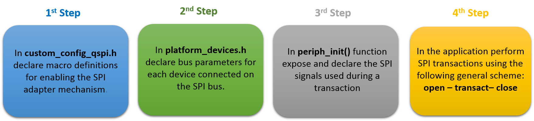
Fig. 2 The Four-Step Process for Setting an Adapter Mechanism
2.1. Header Files
The header files related to adapter functionality can be found in /sdk/adapters/include. These files
contain the APIs and macros for configuring the majority of the available peripheral hardware blocks.
In particular, this tutorial focuses on the adapters that are responsible for the SPI peripheral hardware
block. Table 1 briefly explains the header files related to SPI adapters (red indicates the
path under which the files are stored while green indicates which ones are used for SPI operations).
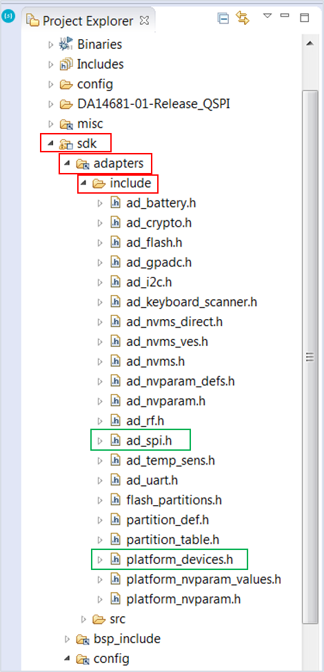
Fig. 3 Headers for SPI Adapters
| Filename | Description |
|---|---|
| ad_spi.h | This file contains the recommended APIs and macros for performing SPI related operations. Use these APIs when accessing the SPI peripheral bus. |
| platform_devices.h | This file contains all the device parameters. These devices may be connected to the Dialog family of devices via a peripheral bus (for example, SPI, I2C, UART) or a peripheral hardware block (for example, GPADC). |
2.2. Preparing an SPI Operation
- As illustrated in Fig. 4, the first step for configuring the SPI adapter
mechanism is to enable it by defining the following macros in
/config/custom_config_qspi.h:
/*
 * Macros for enabling SPI operations using Adapters
 */
#define dg_configUSE_HW_SPI                     (1)
#define dg_configSPI_ADAPTER                    (1)

Fig. 4 First Step for Configuring the SPI Adapter Mechanism.
From this point onwards, the overall adapter implementation with all its integrated functions is available.
- The second step, is to declare all the devices externally connected on the SPI bus.
A device can be considered a set of settings describing the complete SPI interface. These settings are applied
every time the device is selected and used. To do this, the SDK uses a macro, named
SPI_SLAVE_DEVICE:
/*
 * Macro for setting SPI bus parameters
 */

SPI_SLAVE_DEVICE(bus, name, cs_port, cs_pin, _word_mode, pol_mode, _phase_mode,
                                                                  xtal_div, dma_channel)

Fig. 5 Second Step for Configuring the SPI Adapter Mechanism
| Argument Name | Description |
|---|---|
| bus | The DA1468x family of devices features two distinct SPI hardware blocks. Valid values are SPI1 and SPI2. |
| name | Declare an arbitrary alias for the SPI interface (for instance, My_slave_device). This name should be used for opening that specific device. |
| cs_port | Slave Chip Select line: this can be any available port on the DA1468x chip. |
| cs_pin | Slave Chip Select line: this can be any available pin on the DA1468x chip. |
| _word_mode | The size of each data packet sent over the bus. Valid values are those from HW_SPI_WORD enum in /sdk/peripherals/include/hw_spi.h. |
| pol_mode | Clock polarity. Valid values are those from HW_SPI_POL enum in /sdk/peripherals/include/hw_spi.h. |
| _phase_mode | Clock phase. Valid values are those from HW_SPI_PHA enum in /sdk/peripheral/include/hw_spi.h. |
| xtal_div | SPI interface speed. Valid values are those from HW_SPI_FREQ enum in /sdk/peripherals/include/hw_spi.h. |
| dma_channel | The DA1468x family of devices features eight general-purpose DMA channels that can be used for various transactions. This field defines the DMA number for the RX channel. TX will have the next number and it is automatically assigned by the adapter mechanism. |
Note
In contrast with the I2C adapters, SPI adapters share the same macro whether or not a DMA channel is
used for a transaction. Therefore, if a DMA channel is not needed a value equal to -1
should be declared. Also note that DMA RX/TX channels must be set in pairs, that is, 0/1, 2/3, 4/5 and 6/7.
Thus, RX channel must always be set to an even number (0, 2, 4, 6).
The DA1468x family of devices incorporates two distinct SPI blocks namely SPI1 and SPI2. Depending on the SPI interface used, device declarations must be placed between the correct macro indicators inplatform_devices.h:
/* Declare SPI bus configurations for devices connected to SPI1 hardware block */
SPI_BUS(SPI1)

/*
 * Use SPI_SLAVE_DEVICE() for each device declaration
 */

SPI_BUS_END


/* Declare SPI bus configurations for devices connected to SPI2 hardware block */
SPI_BUS(SPI2)

/*
 * Use SPI_SLAVE_DEVICE() for each device declaration
 */

SPI_BUS_END
- As illustrated in Fig. 6, the third step is the declaration of the SPI signals. The user can multiplex and expose SPI signals on any available pin on DA1468x SoC.
static void prvSetupHardware( void )
{

   /* Init hardware */
   pm_system_init(periph_init)

}
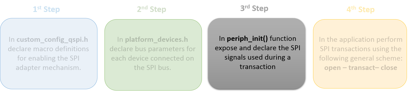
Fig. 6 Third Step for Configuring the SPI Adapter Mechanism
Note
When the system enters sleep it loses its pin configurations. Thus, it is essential for the pins to be
reconfigured to their last state as soon as the system wakes up. To do this, all pin configurations
must be declared in periph_init() which is supervised by the Power Manager of the system.
- Having enabled the SPI adapter mechanism, the developer is able to use all the available APIs for performing SPI transactions. The following describes the required sequence of APIs in an application to successfully execute an SPI write/read operation.
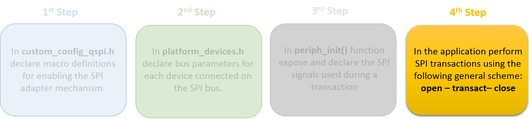
Fig. 7 Fourth Step for Configuring the SPI Adapter Mechanism.
ad_spi_init()This must be called once at either platform start (for instance, in
system_init()) or task initialization to perform all the necessary initialization routines.
ad_spi_open()Before using the SPI interface, the application task must open the device that will access the bus. Opening a device, involves enabling the SPI controller. If the device is the only connected device on the SPI bus, configuration of the SPI controller also takes place. The function returns a handler to the main flow for use in subsequent adapter functions. Subsequent calls from other tasks simply return the already existing handler.
ad_spi_bus_acquire()This API is optional since it is automatically called upon a write/read transaction and is used for locking the SPI bus for the given opened device. This function should be called when the application task wants to communicate to the SPI bus directly using low level drivers.
Note
The function can be called several times. However, it is essential that the number of calls must match
the number of calls to ad_spi_bus_release().
Perform a write/read transaction either synchronously or asynchronously.
After opening a device, the application task(s) can perform any read/write SPI transaction either synchronously or asynchronously. Please note that all the available APIs for writing/reading over the SPI bus, nest the corresponding APIs for acquiring and releasing a device.
ad_spi_bus_release()This function must be called for each call to
ad_spi_bus_acquire().
ad_spi_close()After all user operations are done and the device is no longer needed, it should be closed by the task that has currently acquired it. The application can then switch to other devices connected on the same SPI bus. Remember that the SPI adapter implementation follows a single device scheme, that is only one device can be opened at a time.
2.3. SPI Transactions
Write and read functions can be divided into two distinct categories:
- Synchronous Mode
- Asynchronous Mode
2.3.1. Synchronous Mode
In synchronous mode, the calling task is blocked for the duration of the write/read access but other tasks are not. The mechanism initially waits for the SPI bus to become available and then blocks the calling task until a transaction is completed. Once a write/read process is finished, the SPI bus is freed and further write/read transactions over the SPI bus can take place.
Code snippet of a typical write followed by a read synchronous SPI transaction:
// Open the device that will utilize the SPI bus
spi_device dev = ad_spi_open(My_Slave_Device);

// Perform SPI transactions to the already opened device
ad_spi_transact(dev, command, sizeof(command), response, sizeof(response));

// Close the already opened device
ad_spi_close(dev);
The above code performs a write transaction followed by a read transfer. First, the chip select line is activated for the slave device and then data is sent over the SPI bus. When the current transaction is finished, the device changes to read mode and reads data from the connected device. Finally, the chip select line is deactivated when the transaction has finished.
Note
The aforementioned API can also be used for write only or read only transactions by providing a NULL
pointer in the corresponding input parameter. For example, to perform a write only operation:
ad_spi_transact(dev, command, sizeof(command), NULL, 0);
2.3.2. Asynchronous Mode
In asynchronous mode, the calling task is not blocked by the write or read operation. It can continue with other operations while waiting for a dedicated callback function to be called, signaling the completion of the read or write transaction. SPI adapters allow developer to perform SPI transactions that consist of a number of reads, writes, and callback calls. This provides a time-efficient way to manage all SPI related actions. Most of the actions are executed within ISR context. There are a number of arguments-actions that should be used to perform various SPI transaction schemes. Table 3 explains all the available arguments that can be used to declare an SPI transaction scheme.
| Argument Name | Description |
|---|---|
| SPI_CSA | Use this argument to select the Chip Select line. |
| SPI_CSD | Use this argument to deselect the Chip Select line. |
| SPI_SND() | Use this argument to send data over SPI bus. |
| SPI_RCV() | Use this argument to read data over SPI bus. |
| SPI_SRCV() | This argument is a combination of a write followed by a read SPI transaction. |
| SPI_CB0() | Declare a callback function that should be called when finishing with all defined SPI actions. Developer cannot pass any data in the callback function. |
| SPI_CB1() | Declare a callback function that should be called when finishing with all defined SPI actions. Developer can pass data in the callback function. |
| SPI_END | Use this argument to mark the end of an SPI transaction scheme. This argument should be the last declared action. |
Code Snippet of a typical write followed by a read asynchronous SPI transaction:
// Open the device that will utilize the SPI bus
spi_device dev = ad_spi_open(My_Slave_Device);

// Perform SPI transactions to the already opened device
ad_spi_async_transact(dev, SPI_CSA,                             // Activate the Chip Select line
                           SPI_SND(command,  sizeof(command) ), // Initiate an SPI write operation
                           SPI_RCV(response, sizeof(response)), // Initiate an SPI read  operation
                           SPI_CB0(final_callback)            , // Function to be called upon finishing with all the above SPI operations
                           SPI_CSD,                             // Deactivate the Chip Select line
                           SPI_END);                            // Indicate the end of SPI operations

// Make sure that the current transaction completes

// Close the already opened device
ad_spi_close(dev);
When performing SPI operations in asynchronous mode, the following should be considered:
- Callback functions are executed from within Interrupt Service Routine (ISR) context. Therefore, a callback’s execution time should be as short as possible and not contain complex calculations. Please note that for as long as a system interrupt is serviced, the main application is halted.
- If the callback function is the last action to be performed, then resources (SPI device and bus) are released before the callback is called.
- Do not call asynchronous related APIs consecutively without guaranteeing that the previous asynchronous transaction is finished.
- After the callback function is called, it is not guaranteed that the scheduler will give control to the freeRTOS task waiting for that transaction to complete. This is important to consider if several tasks are using this API.
2.4. Duplex Transmissions
The SPI hardware block supports a Duplex mode separately from write or read only mode. In Duplex mode, at the same time as data is shifted out from the Master Output pin (MOSI), data is shifted in from the Master Input pin (MISO). This feature can be useful when loopback tests are needed to validate the functionality of the SPI interface or when an SPI transaction between devices needs to do so. SDK provides an API along with a data structure that should be used for duplex SPI transactions.
| Name | Description |
|---|---|
| ad_spi_complex_transact() | Use this function to perform duplex transactions on an SPI bus. Please note that buffers for both written and read data should be provided. This function can also be used for complex transactions, that is, it can perform several transactions in one Chip Select activation. The total number of transactions is determined by the last input parameter. For instance, when two identical transactions are needed, set this parameter to ‘2’. |
| spi_transfer_data | Use this structure when performing either a complex or duplex SPI transaction. |

Fig. 8 Duplex SPI Transaction