3. Measuring power
As mentioned in the previous sections depending on the configuration used a different datapoint will be generated, therefore one needs to define a very specific scenario providing detailed description of all the parameters that can influence a measurement. The test is designed in such a way to get a representative measurement of a specific feature or use-case, serving an evaluation purpose. In this section we will provide measurements for the following cases which covers both performance evaluation and battery lifetime estimation.
Datasheet numbers/: The purpose is to provide datapoints on isolated parts of the system on different power modes.
Executing from RAM or i-cache at different clock rates/: Purpose is to estimate cost of code execution.
Bluetooth events/: Numbers providing power consumption on specific Bluetooth events.
Use case scenarios/: Power consumption when executing simple applications like the proximity reporter, a graphics demo, or periodic wake-up to probe a sensor.
3.1. Datasheet numbers
The numbers are provided in the DC Characteristics table of the datasheet. The power number includes typical numbers measured on very specific conditions which are described in the condition cell of every table entry. The configuration is not the same as the one typically used in the SDK since the scope of those numbers are to show the best capabilities of the HW in terms of power consumption if properly configured. On the other hand on a typical application environment a less aggressive configuration is required, similar to what the standard SDK provides. The application used is referred as characterization software.
Parameter |
Description |
Conditions |
Typ. Value |
|---|---|---|---|
IBAT_IDLE |
battery supply current |
CPU is idle (WFI) hclk = 32 MHz (RCHS) PLL off. slow PCLK= 2MHz fast PCLK = 4MHz DC-DC on. FLASH off peripherals off VDD = 0.9V VBAT = 3 V |
0.9 mA |
IBAT_RUN_32MHz |
average active battery supply current |
CPU is executing from RAM hclk = 32 MHz (RCHS) PLL off. slow PCLK = 2 MHz fast PCLK = 4 MHz DC-DC on. FLASH off Peripherals off VDD = 0.9V VBAT = 3 V. |
2.1 mA |
IBAT_RUN_96MHz |
average active battery supply current |
CPU is executing from RAM. hclk = 96 MHz (RCHS) PLL off. slow PCLK = 2 MHz fast PCLK = 12 MHz DC-DC on. FLASH off Peripherals off VDD = 1.2V VBAT = 3 V. |
7.9 mA |
IBAT_RUN_160MHz |
average active battery supply current |
CPU is executing from RAM. hclk = 160 MHz PLL on. XTAL32M on slow PCLK = 2 MHz fast PCLK = 20 MHz DC-DC on. FLASH off Peripherals off VDD = 1.2V. VBAT = 3 V. |
13 mA |
IBAT_HIBERN |
battery supply current |
Hibernation mode no RAM retained all clocks off DCDC off Vclamp default FLASH off. VBAT = 3V. |
0.2 μA |
IBAT_DP_SLP |
battery supply current |
Deep Sleep mode No RAM retained. RCX on RTC on. RCLP = 32 kHz DC-DC on. VDD = 0.9 V LDO_V30_RET on Default Bandgap Refresh val VBAT= 3 V. |
6 μA |
IBAT_VAD |
battery supply current |
Voice Activity Detection Sleep mode; 8kB iCache 256 kB RAM retained RCX on. RTC on RCLP = 32 kHz DC-DC on. VDD = 0.9V LDO_V30_RET on FLASH in Power Down Bandgap Refresh Default VBAT = 3 V. |
16.2 μA |
IBAT_EX_SLP_caches_256K |
battery supply current |
Extended Sleep mode 8kB i-cache 256 kB (data) RAM retained. RCX on RTC on RCLP = 32 kHz DC-DC on VDD = 0.9 V LDO_V30_RET on FLASH in Power Down Bandgap Refresh Default VBAT = 3 V. |
8.7 μA |
IBAT_EX_SLP_caches_512K |
battery supply current |
Extended Sleep mode 8kB iCache 512 kB RAM retained RCX on. RTC on RCLP = 32 kHz DCDC on VDD = 0.9 V LDO_V30_RET on FLASH in Power Down mode Bandgap Refresh Default VBAT = 3 V. |
10.8 μA |
IBAT_EX_SLP_caches_1MB |
battery supply current |
Extended Sleep mode 8kB iCache 1024 kB RAM retained RCX on RTC on RCLP = 32 kHz DCDC on VDD = 0.9 V LDO_V30_RET on FLASH in Power Down mode Bandgap Refresh Default VBAT = 3 V. |
14.4 μA |
IBAT_EX_SLP_caches_1.5MB |
battery supply current |
Extended Sleep mode 8kB iCache 1536 kB RAM retained RCX on. RTC on RCLP = 32 kHz. DCDC on VDD = 0.9 V. LDO_V30_RET on FLASH in Power Down Bandgap Refresh Default VBAT = 3 V. |
18.5 μA |
IBAT_SensorNode |
average battery supply current |
SNC is running from RAM hclk = 32MHz (RCHS) slow PCLK = 32 MHz fast PCLK = 4 MHz DC-DC on CPU off FLASH off Peripherals off VDD = 0.9V VBAT= 3 V. |
1.4 mA |
IBAT_BLE_RX_32M |
peak battery supply current |
BLE receive mode fCLK = 32 MHz CPU off DC-DC on FLASH in Power Down VBAT= 3 V. |
4.2 mA |
IBAT_BLE_TX_32M |
peak battery supply current |
BLE transmit mode fCLK = 32MHz. CPU off DC-DC on FLASH in Power Down VBAT = 3 V. |
5.3 mA |
3.2. Executing code from cache or RAM at different clock rates
The target here is to estimate the cost of executing specific block of code at different clock rates. Cache and RAM are used as sources of the code and OSPI / QSPI is usually excluded since it will add a big amount of power which depends on the flash device used and the settings of the OSPI/QSPI
ID |
Description |
Memory used |
Clock RCHS32M |
Clock RCHS96M |
Clock PLL160M |
|---|---|---|---|---|---|
1 |
Idle (WFI) |
RAM |
0.94mA |
2.20mA |
2.8mA |
2 |
Data Move |
RAM |
2.24mA |
8.64mA |
14.4mA |
3 |
FPU |
RAM |
1.77mA |
6.33mA |
13.36mA |
4 |
NOP |
RAM |
1.91mA |
6.96mA |
11.32mA |
5 |
Data Move |
Cache |
2.56mA |
10.29mA |
16.95mA |
6 |
FPU |
Cache |
1.96mA |
9.25mA |
11.78mA |
7 |
NOP |
Cache |
2.39mA |
9.41mA |
15.44mA |
All measurements have been done using the DA1470x DK and VBAT is at 3V.
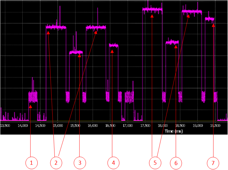
3.3. Bluetooth events
CMAC always executes code from RAM using a 32MHz clock and thus the system should run on VDD 0.9V. Of course if the application processor is awake using a higher speed clock the VDD setting may be overruled and CMAC may execute code at VDD 1.2V.
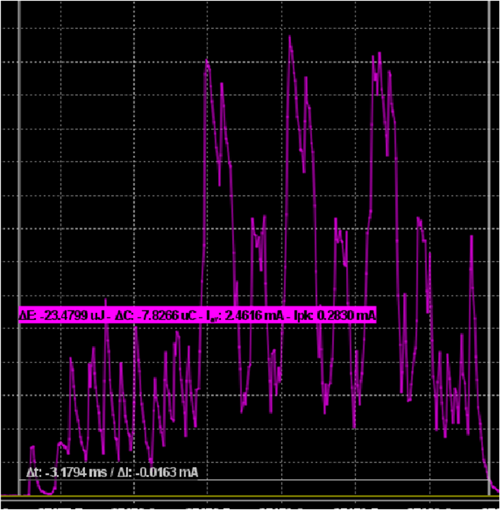
As shown in the figure a 3 channel advertize with almost a full payload will require 7.8uC from a 3V power source hooked at VBAT. The event will take almost 3.18mS from wake-up to finish.
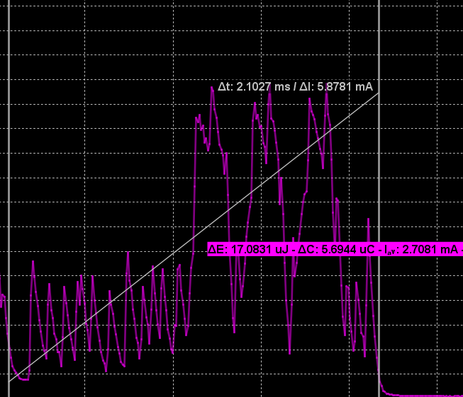
A 3 channel non connectable advertize will require 5.9 uC from a 3V power source. The event will take 2.1 mS from wake-up to finish.
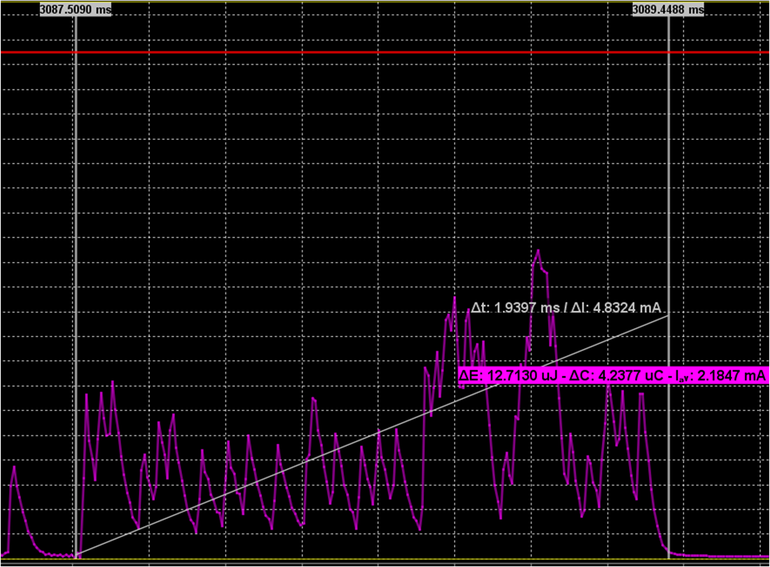 A connection event which does not carry any data will require 4.24uC from a 3V power source. The event requires 1.94mS
from wake-up to finish.
A connection event which does not carry any data will require 4.24uC from a 3V power source. The event requires 1.94mS
from wake-up to finish.
3.4. Usecase numbers
Scope of this type of measurements is to provide datapoints that a customer can use to form a battery lifetime calculator for a specific application. The DA1470x is best fitted for wearables applications. Usually the applications will have 2 states when in use by the end user. * An idle state where the user does not interact with the device. * An active one where the user interacts with the UI of the device. The first state can be emulated with the device advertizing or being connected at a slow interval together with a periodic wake-up of the device for sensor probing, data processing and logging. The active state is mainly defined by the power consumption of the graphics since the user interacts with the device. A demo using graphics including animation will give a good sense of the power consumption of the system at this state.
3.4.1. Idle state
In our simplified model the device will wake up for 3 different type of events.
ID |
Clock |
Duration |
Period |
Charge per event |
Description |
|---|---|---|---|---|---|
Evt1 |
RCHS32M |
0.5 sec |
34.2 uC |
9.9 ms |
Device is waking up every 500mS, probes the sensor, stays active (sensor sampling + data processing) for ~10ms @32MHz and goes back to sleep. |
Evt2 |
XTAL32M |
1 sec |
9.0 uC |
3.9 ms |
Device is advertizing |
Evt3 |
RCHS32M |
1 min |
39.4 uC |
10.7 ms |
Write 1K of data to the storage flash using the flash adapter. |
Summing up and adding another 18uA x 97.6% for the power consumption during sleep; since 97.6% is the approximate time the device is sleeping the Idle State scenario will require
18uA * 97.6% + 34.2/0.5 uA + 9.0/1 uA + 39.4/60 uA = 95.73 uA
3.4.2. Active state
To provide a data point for the active state we will use a watch face demo with clock hands. This is implemented using LVGL library and draws a complex watch face using 16 bit colors. 2 layers are used and all frame buffers are stored internally in the system ram. The display refresh period is set at 100mSec. The resolution of the frame buffer is at 390 x 390. The system clock used is 96 Mhz and it takes on average 23ms to complete a drawing event. The average power consumption of the DA1470x to serve such a scenario is kept at 3.1mA when powered from a 3.3V power source with the peak current reaching 28mA.