6. SmartSnippetsToolbox Support
6.1. SmartSnippetsToolbox
DA1469x Development Kits use Macronix MX25U3235F 32Mbit QSPI Flash memory and also support out-of-the-box GigaDevice GD25LE32 and Winbond W25Q32FW. The SDK contains a driver for each one of the aforementioned QSPI Flash Options and SmartSnippetsToolbox™ fully supports them as well.
However for QSPI Flash options of different size, model or even vendor, where a custom driver needs to be created, certain steps must be followed in order for them to become accessible by SmartSnippetsToolbox™ as well.
The processes that comprise the backbone of SmartSnippetsToolbox™ QSPI Flash related tools can be divided into two categories: Running on the Host computer and running on the Device.
On the device side, the uartboot loader binary is downloaded to perform all the transactions from and to the QSPI Flash.
As expected, on the host side even if a Graphical User Interface is used, an application similar to cli_programmer is used that will be issuing the commands through UART that uartboot will receive and execute.
6.2. SmartSnippetsToolbox Flash Tools Initial Flow
In order for any Flash related tool of SmartSnippetsToolbox™ to be able to access the Flash they first need to perform a connect sequence. This is achieved by clicking the ‘connect’ button. Once the button is clicked, SmartSnippetsToolbox™ application reads the configuration XML file, sets the Baudrate to the value read from the XML file and requests for a hardware reset on the device. Once RESET is detected, uartboot.bin will be downloaded into the device’s RAM and the device will start its execution.
Next the device will try to read the partition table and if it is successful it will allow other operations to be performed.
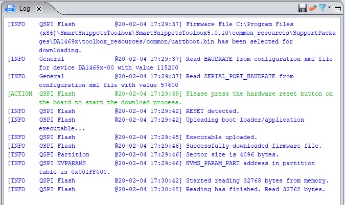
Figure 4 |sst| successful Flash connection and read.
Note
The partition table is read the very first time of a SmartSnippetsToolbox™ session connects to device and and every time a new firmware is burned in the Flash using the toolbox.
Note
Please note that before any attempt to read or write the Flash Memory through UART, uartboot will be downloaded ONLY IF it is not already running in the device.
In turn, if the device is not disconnected from Power(POR) before starting any access to the Flash with a modified uartboot, it is possible that the action will fail at the point where the checksum of the downloaded uartboot is checked, as a stale version of uartboot in the RAM will most likely have a different checksum compared to the one which is part of cli_programmer or is used by SmartSnippetsToolbox™.
6.3. Modifications
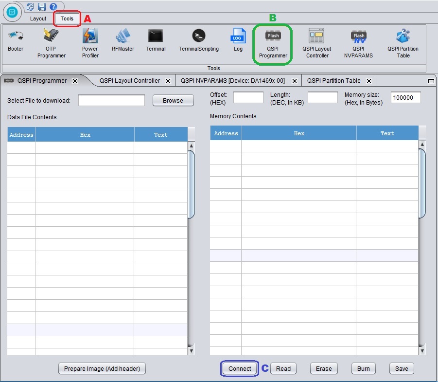
Figure 5 |sst| QSPI Programmer.
Download the desired firmware to the device.
Note
The partition table is created in the Flash the very first time that a new firmware is loaded. It is advised to erase chip before burning any new firmware to avoid having remnants of a stale version of the partition table stored and make sure the device is powered off and on again after the firmware is burned in order for the partition table to be created.
If any extra functionality is added to libprogrammer make sure to copy libprogrammer.dll from {SDK_root}/binaries to {SmartSnippetsToolbox_root}/common_resources/SupportPackages/DA1469x/toolbox_resources/(windows/linux).
Copy uartboot.bin from {SDK_root}/binaries to {SmartSnippetsToolbox_root}/common_resources/SupportPackages/DA1469x/toolbox_resources/common.
Note
As a rule of thumb, copy uartboot.bin on every occassion it is required to be rebuilt in order for the device to work properly. The same applies for cases where the partition table is moved.
Run SmartSnippetsToolbox™, pick the device, the communication type, the PORT if using UART and then press Open.
Click on Tools tab( red ‘A’ rectangle) and then QSPI Programmer( green ‘B’ rectangle).
Click the Connect Button( blue ‘C’ rectangle) and follow the instructions on the log window. If the partition table is found then it is possible to have access to the Flash Memory.
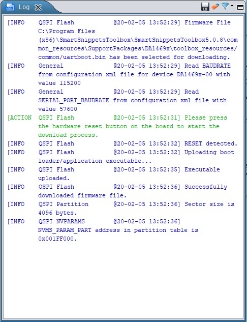
Figure 6 |sst| QSPI Programmer successful connection Log.