As mentioned before, SPS emulates serial cable communication. Data is transferred over UART to BLE and over BLE to UART. For SPS to work properly, the signals UCTS, URTS,URX and UTX of mainboard 376-18-B should connect in a proper way for each DK and module. This section describes the correct way for each chipset to be able to transfer or receive data with the use of SPS.
The configuration of the UART pins described below are located in file user_periph_setup.h.
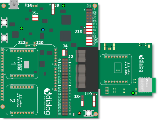
For SPS functionality there are three jumpers needed on the J1 connector of the mainboard 376-18-B at the following pins:
J1:11-J1:12
J1:13-J1:14
J1:17-J1:18
And one jumper cable is needed from J1:15 to J2:7 (P02).
Remove the jumper from J1:19-J1:20 in case it exists.
Figure 26 shows the proper jumpers setup of the J1 header.