2. Getting Started
2.1. Hardware Setup
This manual explains the use of Pro-Kit to show the example, however, you can use the basic kit as well. The setup to implement DSPS example for DA14531 and DA14585/586 is given below.
Note
Using the DA14531 Pro-DK motherboard, you can use either DA14531, DA14531 Module, DA14585 or DA14586 daughterboard with the same fly-wire and jumper connections.
2.1.1. Setup on DA14531 Pro-DK Motherboard
Use the flywires to connect from J1[UTX] to J2[P26], J1[URX] to J2[P25], J1[URTS] to J2[P27] and J1[UCTS] to J2[P28] as shown in Figure 1.
Use the jumpers to enable the SPI Flash and connect the rest of the jumpers as shown in Figure 1.
Connect the Pro-DK to PC via USB cable.
Three LEDs lit up: D1, D2, and D4.

Figure 1 DA14531 Setup on DA14531 Pro-DK: SPI and 4-wire UART for DSPS Execution
Figure 2, Figure 3, and Figure 4 display also the 4-wire UART connections from the Pro-DK motherboard to DA145xx (DA14531/DA14585/DA14586) daughterboard overview.

Figure 2 DA145xx 4-wire UART Connection Overview
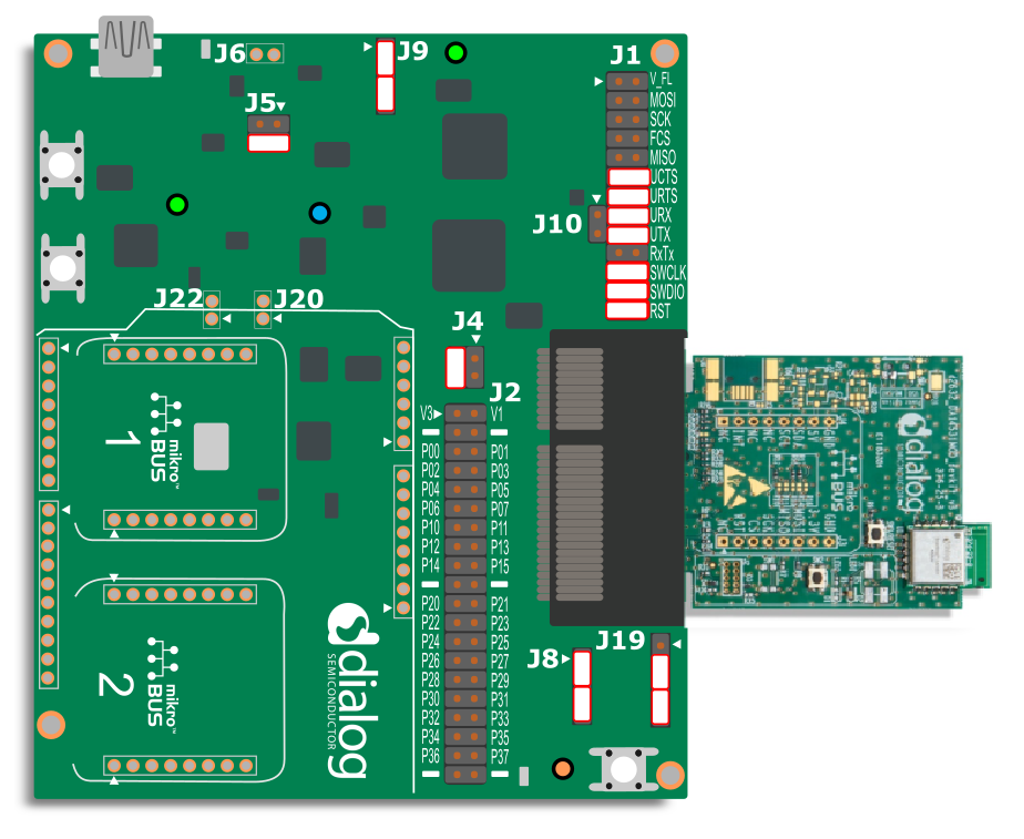
Figure 3 DA14531 Module Setup on the DA14531 Pro-DK: 4-wire UART for DSPS

Figure 4 DA14585/586 Setup on DA14531 Pro-DK: SPI and 4-wire UART for DSPS
2.2. Software Setup
The DSPS SDK comes with the following firmware images. Depending on the SoC and application, the user can select the appropriate firmware.
Pre-compiled binaries provided with the SDK:
DSPS for DA14585/586 as peripheral (dsps_device_585.bin)
DSPS for DA14531 as peripheral (dsps_device_531.bin)
For the examples in the Manual, DSPS for DA14531 device is used. To load the firmware follow the below step:
Load CodeLess firmware into DA14531/DA1458x using SmartSnippets™ Toolbox. Use the Booter over Serial wire debug (SWD) to download the firmware to SysRAM or use Flash Programmer to burn the firmware onto flash and execute from flash. Refer to SmartSnippets™ Toolbox User Manual Chapter 8 and 13.
Open SmartSnippets™ Toolbox, select Board, then Device to select SoC, and lastly click on JTAG as shown in Figure 5.

Figure 5 SmartSnippets Configuration
Go to Programmer, select RAM, browse to your firmware, and then click Download Code Image as shown in Figure 6.
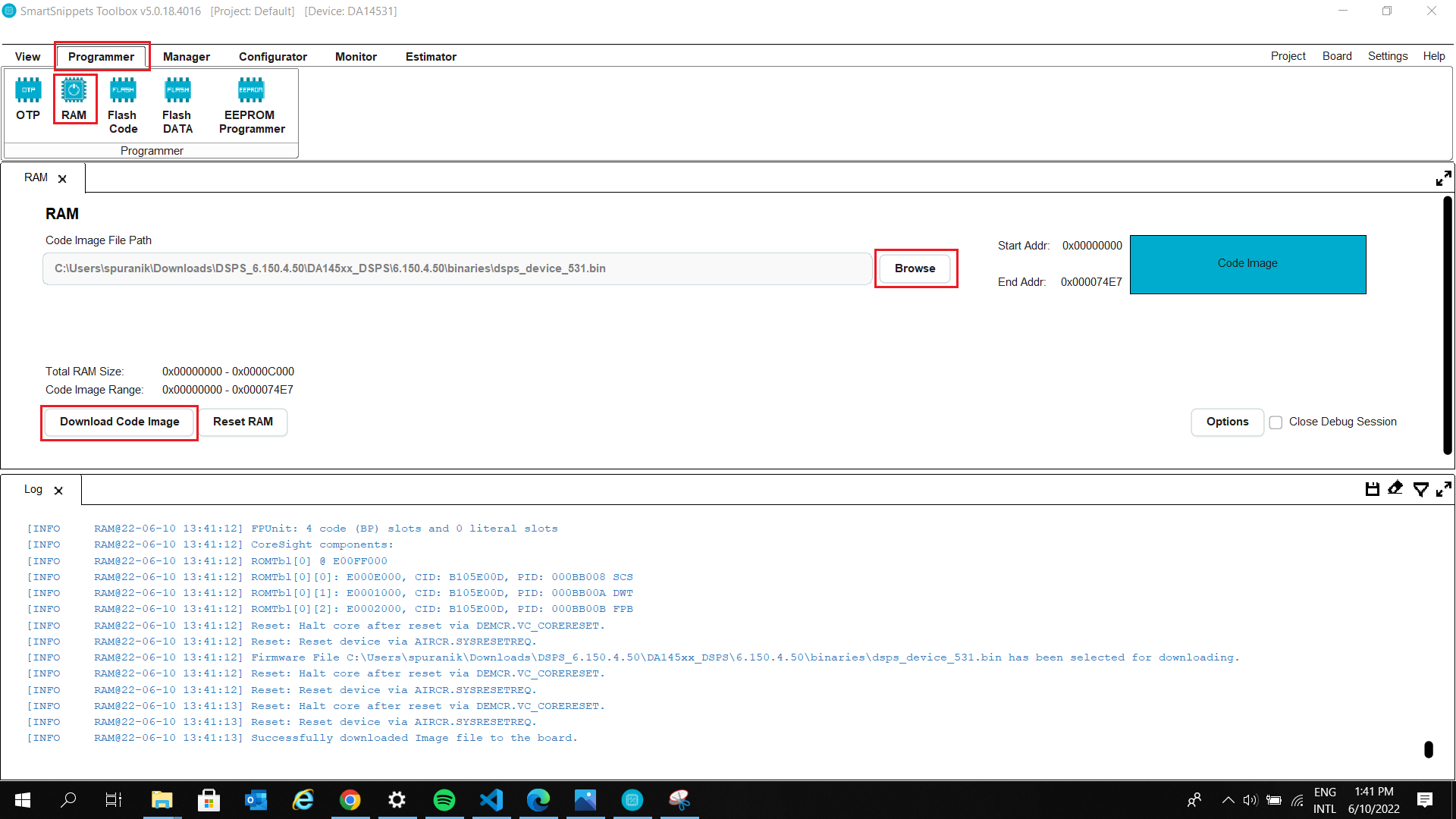
Figure 6 Downloading to SysRAM
Alternatively, Renesas SmartBond™ Flash Programmer tool lets the user program a flash device for the DA14531 SoC. This is a quicker way to get things going with the DSPS. The list of hex files is shown below.
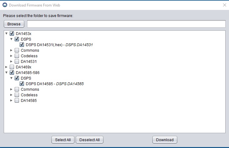
Figure 7 Flash Programmer Tool Download Firmware from Web
The instructions on how to use the tool is explained in the User Manual UM-B-138.
2.3. Running the application
After downloading the firmware and doing the harware setup as shown in the sections before. Follow the below steps to transfer data using DSPS:
Open TeraTerm app with following settings. Two comports will be deceted slect the lower order one for serial communication.

Figure 8 TeraTerm Configuration
Open the SmarConsole app on phone and connect to SPS_531.
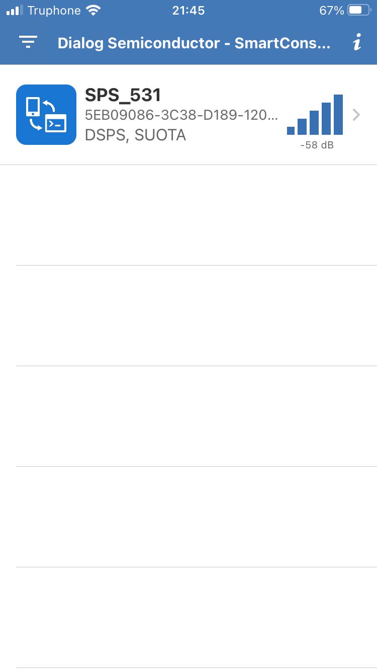
Figure 9 Connect device in SmartConsole
Send data through the app (Figure 9), you can see the Sent data on the TeraTerm screen (Figure 10).
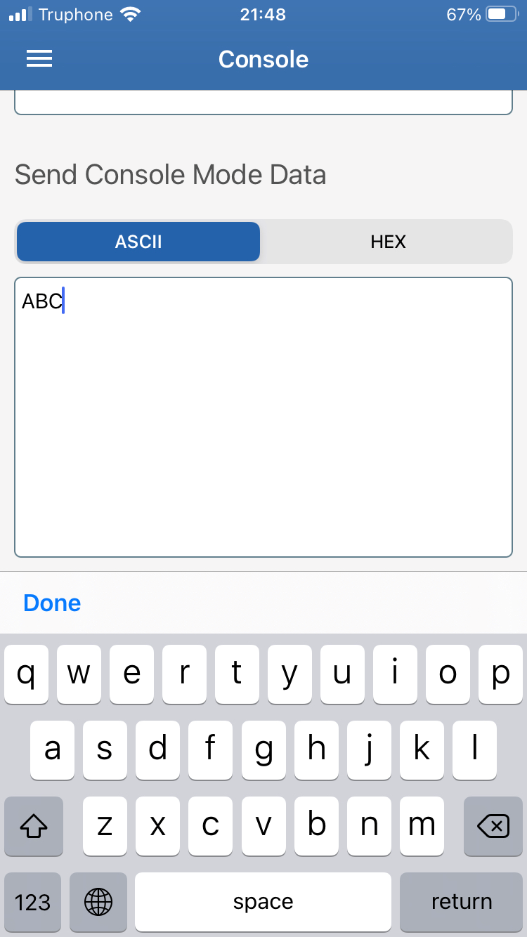
Figure 10 Send data in SmartConsole
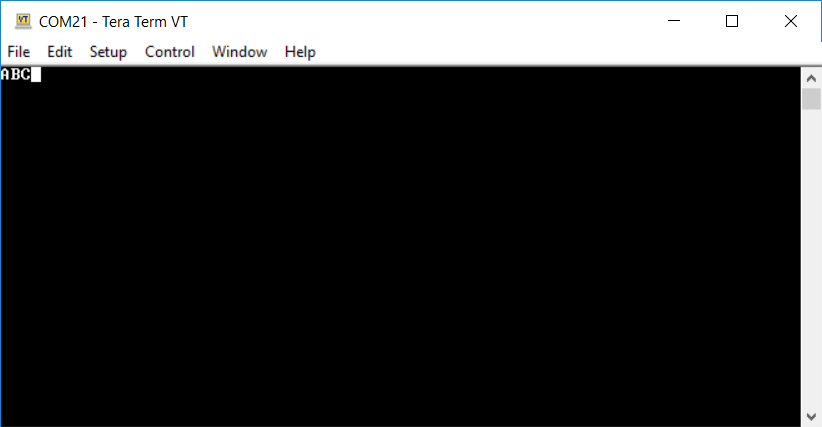
Figure 11 Data received in TeraTerm
In similar way data can be sent throuigh Teraterm console and be received on SmartConsole app.