1. Overview
The Renesas SmartBond™ Flash Programmer tool lets the user program a flash device for the DA1453x, DA1458x, DA1469x and DA1459x SoCs (System on Chip).
This tool allows the user to,
Connect to the target device (Kit Motherboard or Kit Module) via JTAG,
Select the firmware to program the flash
Or simply erase the contents of flash.
DA1453x is referring to DA14531-00, DA14531-01, DA14530, DA14535 and DA14533
The DA14531-00 is the main DA14531 device. The -00 is just a new naming to introduce the variant DA14531-01. The DA14531-01 is a ROM variant of the main DA14531-00.
The DA14535 is a DA14531 upgrade.
The DA14533 is optimized for automotive and industrial applications at higher temperatures, and it is rated as operating up to 105 ºC and compliant with the AEC-Q100 (Grade 2) standard.
DA1458x is referring to DA14585 and DA14586.
DA1459x is referring to DA14592 and DA14594.
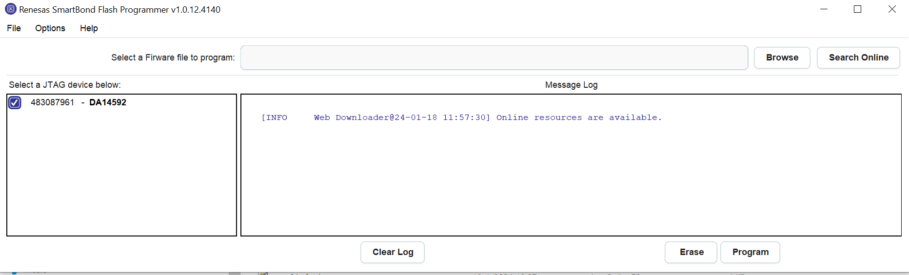
Figure 1 Renesas SmartBond™ Flash Programmer Tool
1.1. Installing the Renesas SmartBond™ Flash Programmer tool
Before installing the Renesas SmartBond™ Flash Programmer tool, make sure that the Segger J-Link software is installed. (Segger J-Link software can be downloaded from Segger website.)
1.2. Hardware setup
The hardware setup to be able to connect to ProDev Kit Motherboard is as shown in the figure below. The board is configured for SPI Flash and JTAG programmer.
The hardware setup to connect the DA14531 development kit:
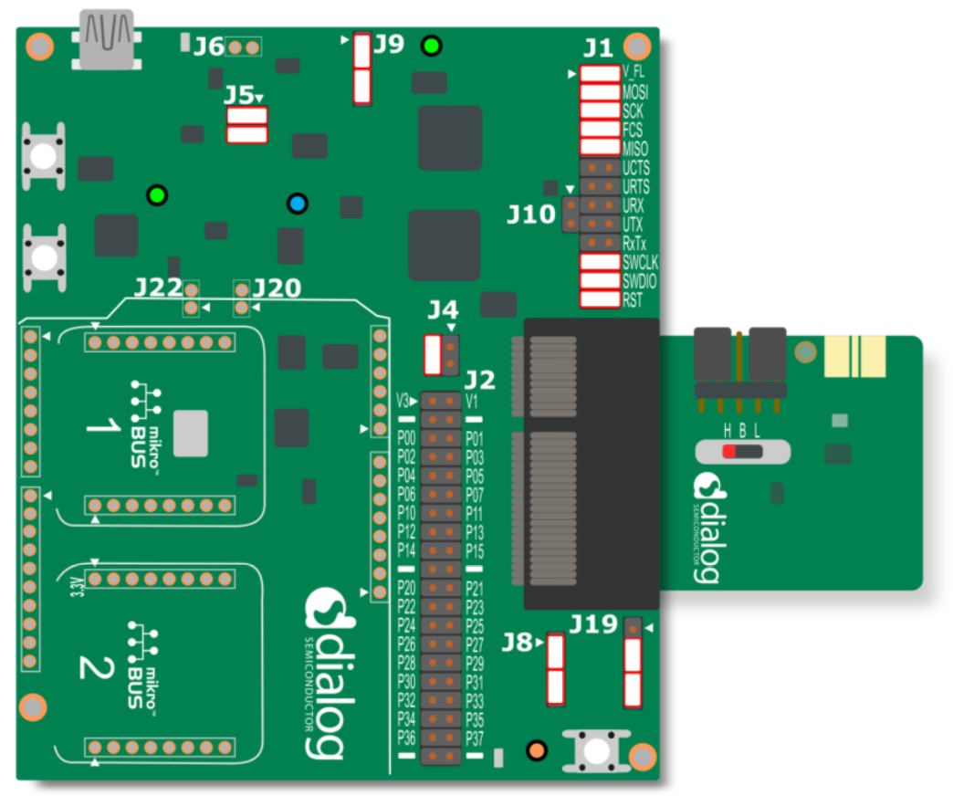
Figure 2 DA14531 ProDev Kit Motherboard connected to DA14531
The hardware setup to connect the DA14535 development kit:
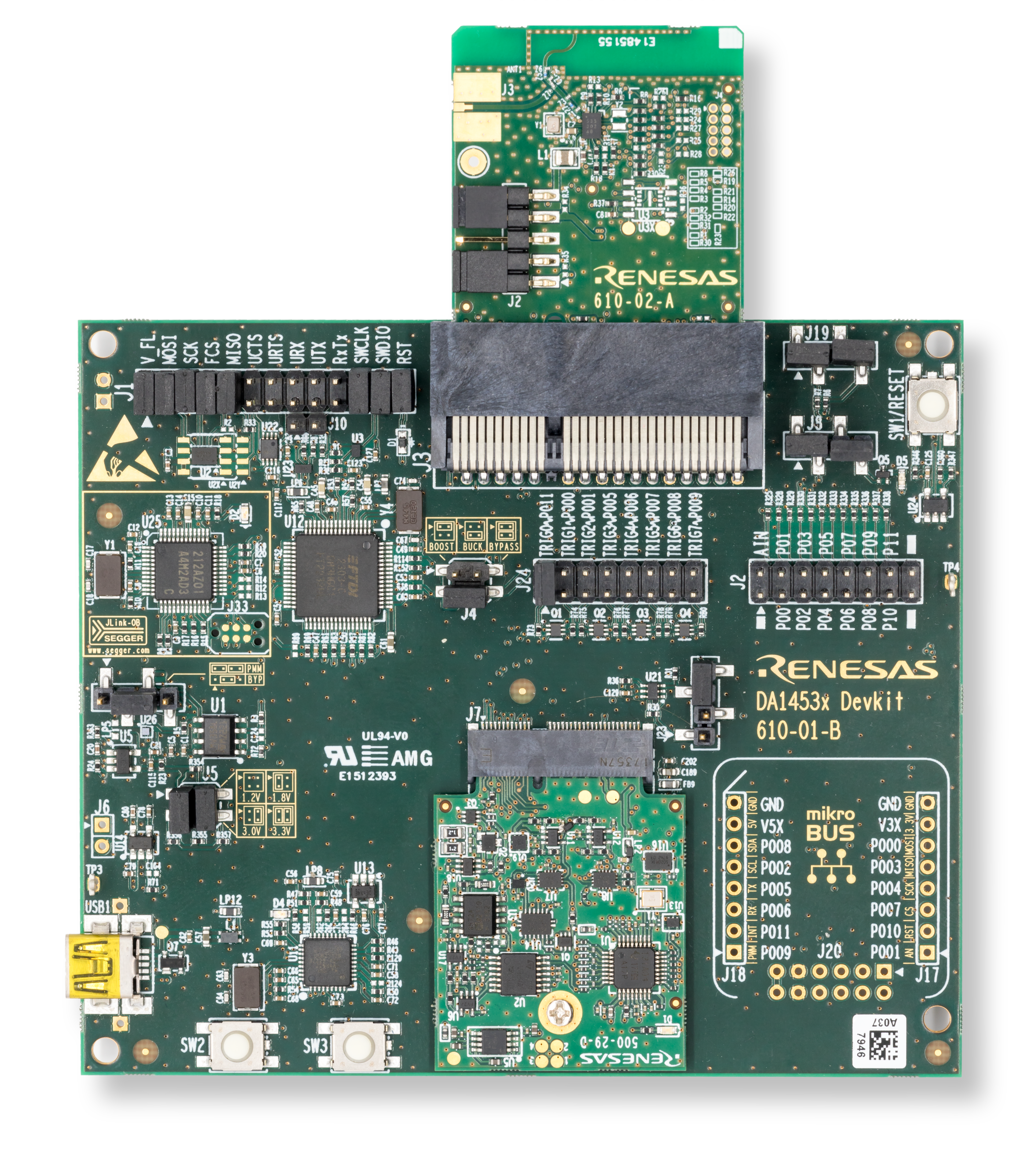
Figure 3 DA1453x ProDev Kit Motherboard connected to DA14535
The hardware setup to connect the DA14533 development kit:
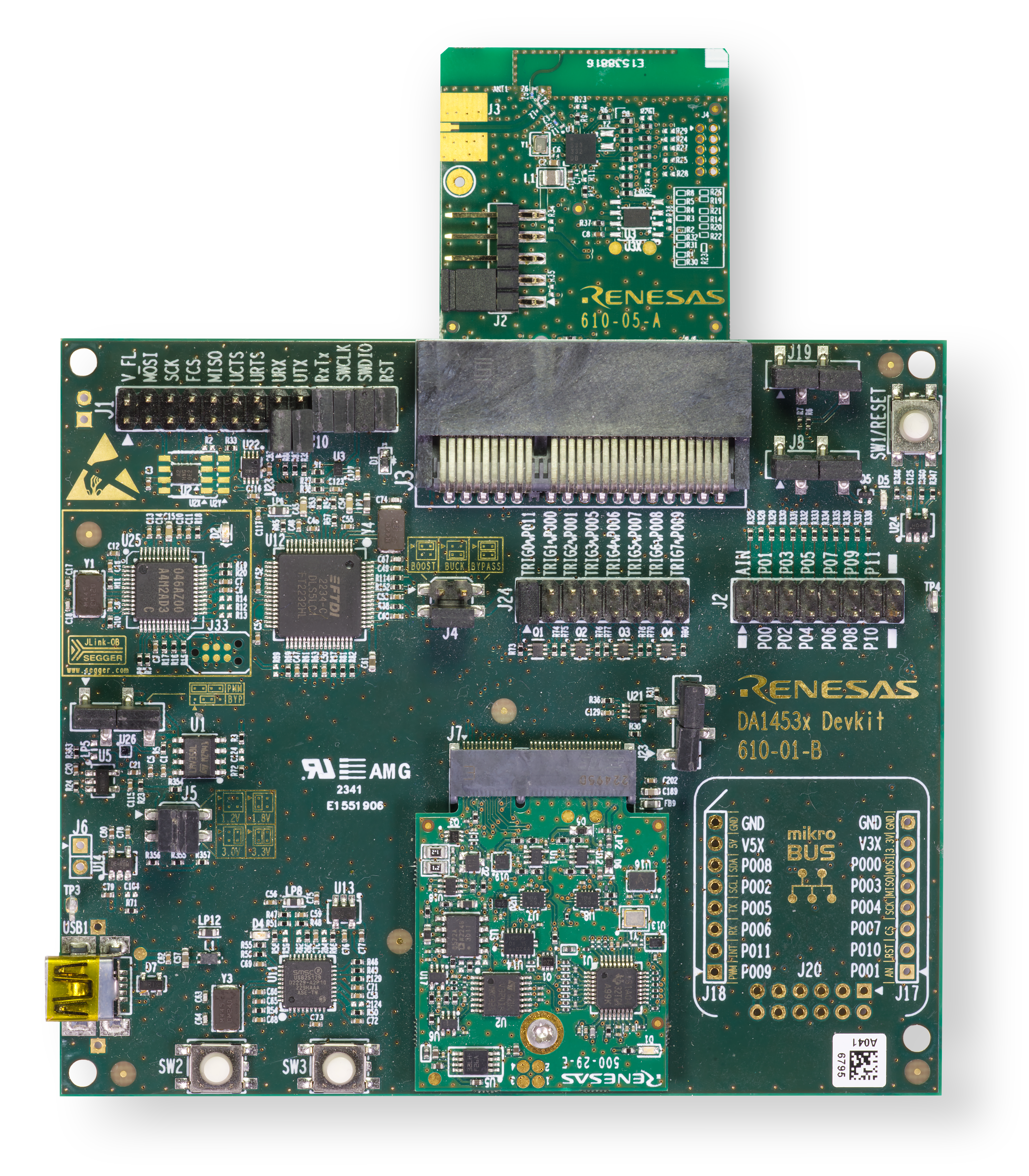
Figure 4 DA14533 ProDev Kit Motherboard connected to DA14533
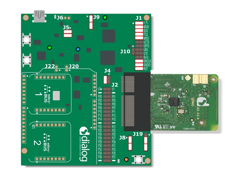
Figure 5 DA145xx ProDev Kit Motherboard connected to DA14585
The DA14531 Module can be connected to the DA14531 ProDev Kit Motherboard, like so,
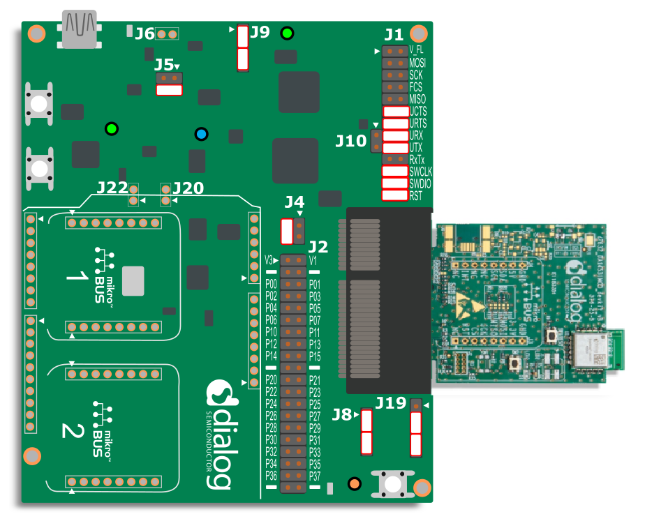
Figure 6 DA145xx ProDev Kit Motherboard connected to DA14531 Module
The DA14531 USB Development Kit switch setting is like so,
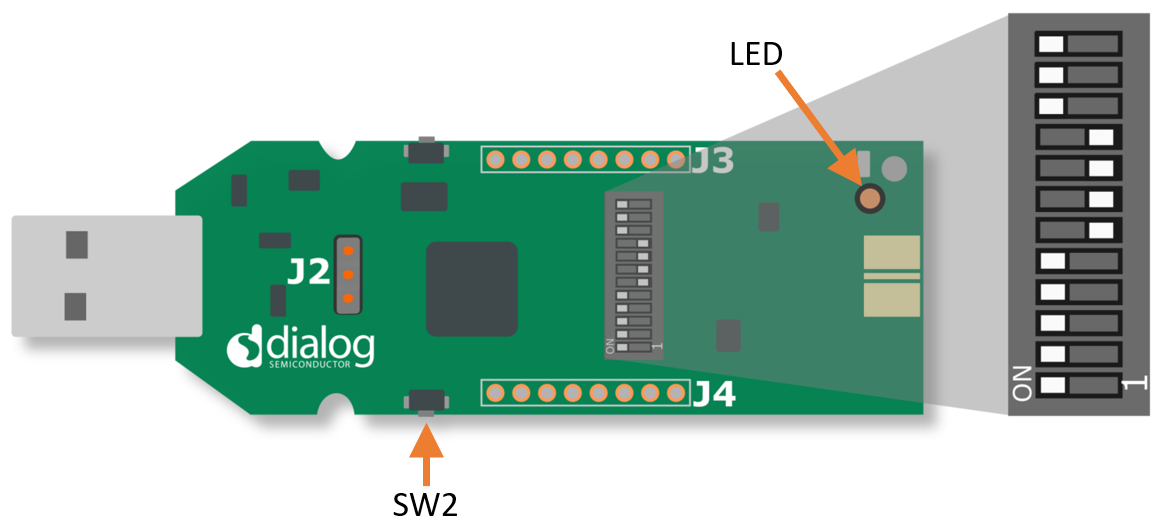
Figure 7 Switch setting on the DA14531 USB Development Kit
Warning
The DA14531 USB Development cannot be configured to boot from flash and operate a 2/4 wire UART interface, you can refer to the section 5.6 of the UM-B-125.
For this reason it is not well suited to being used as a platform for CodeLess.
The hardware setup to be able to connect to DA1469x ProDev Kit Motherboard is as shown in the figure below.
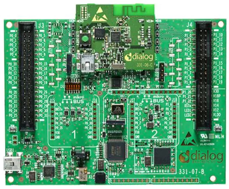
Figure 8 DA1469x ProDev Kit Motherboard connected to DA14695 DB - jumper configuration
The hardware setup to connect the DA14695 USB development kit:
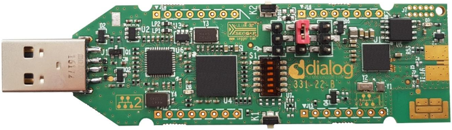
Figure 9 DA1469x USB development kit
The hardware setup to connect the DA14695 Module development kit:
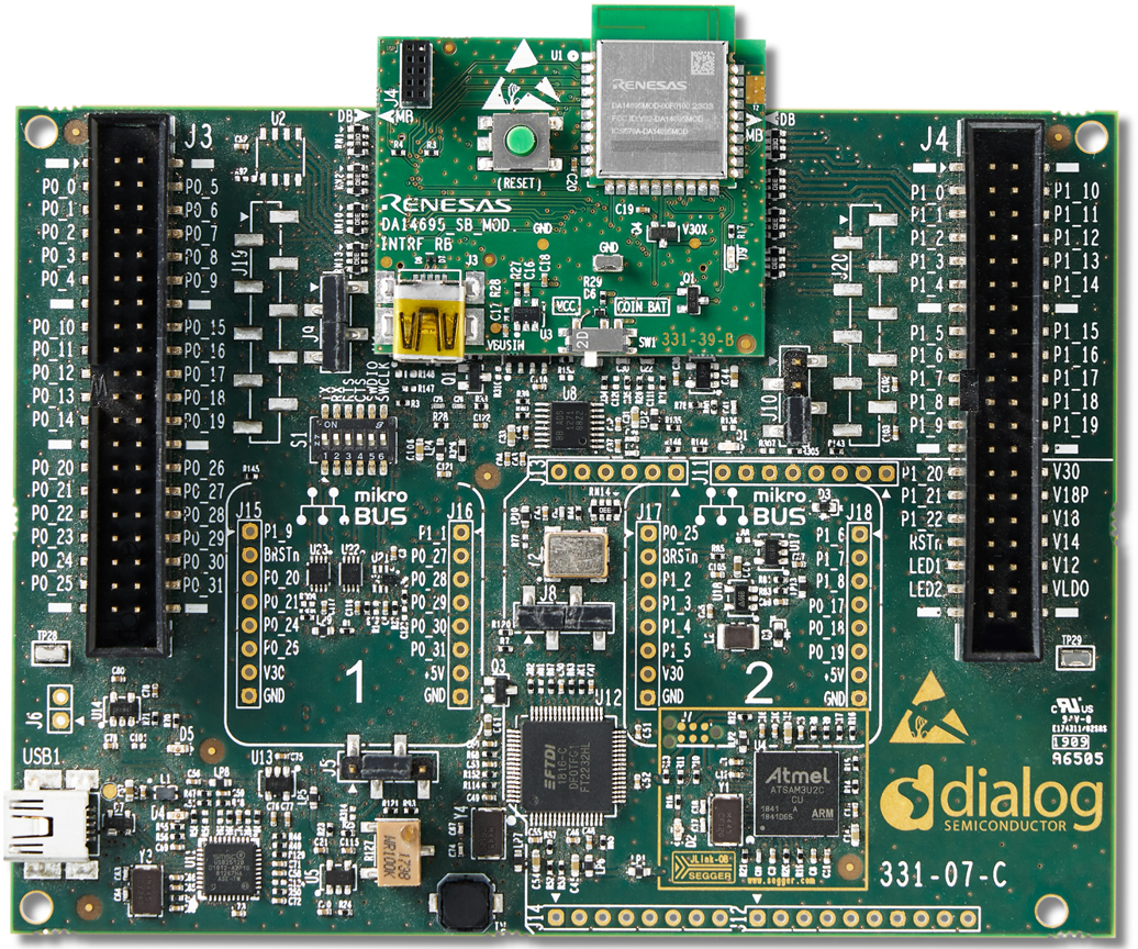
Figure 10 DA14695 Module development kit
The hardware setup to connect the DA14592 development kit:
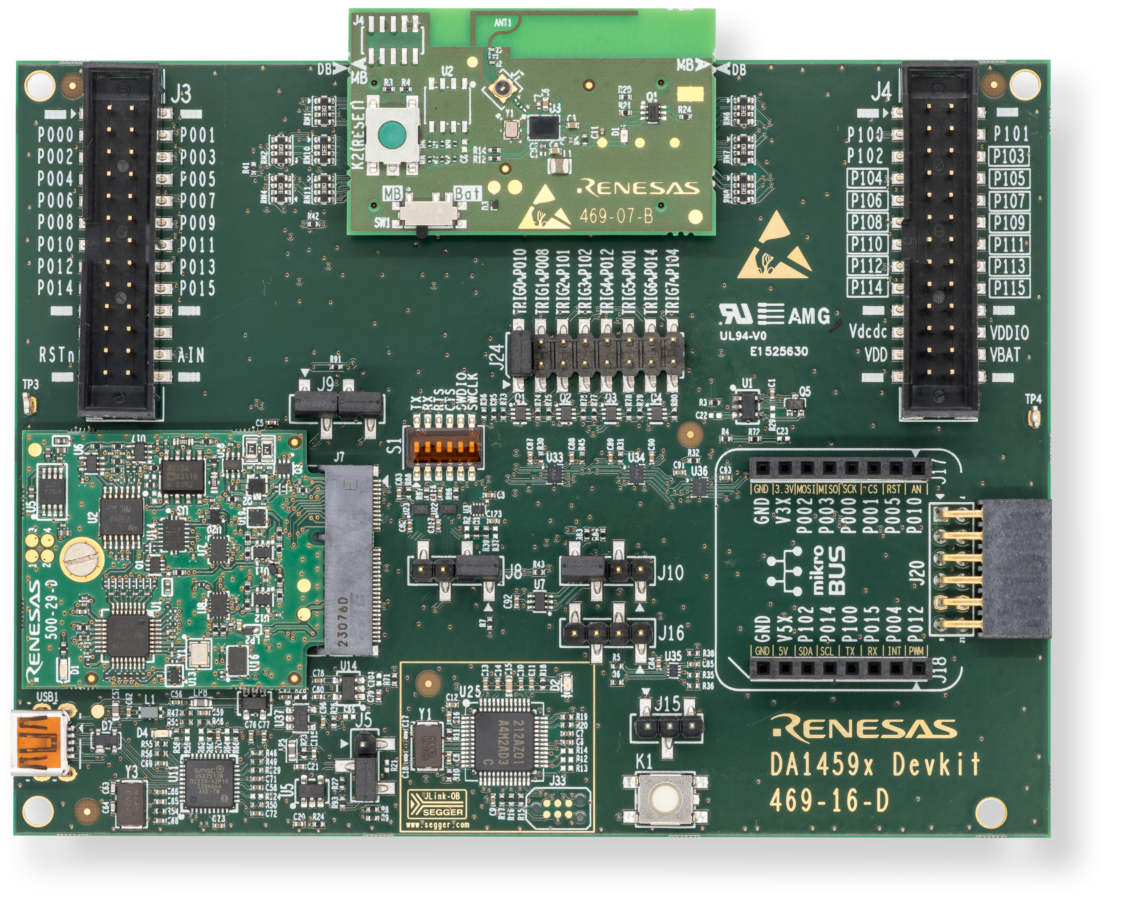
Figure 11 DA14592 development kit
The hardware setup to connect the DA14594 development kit:
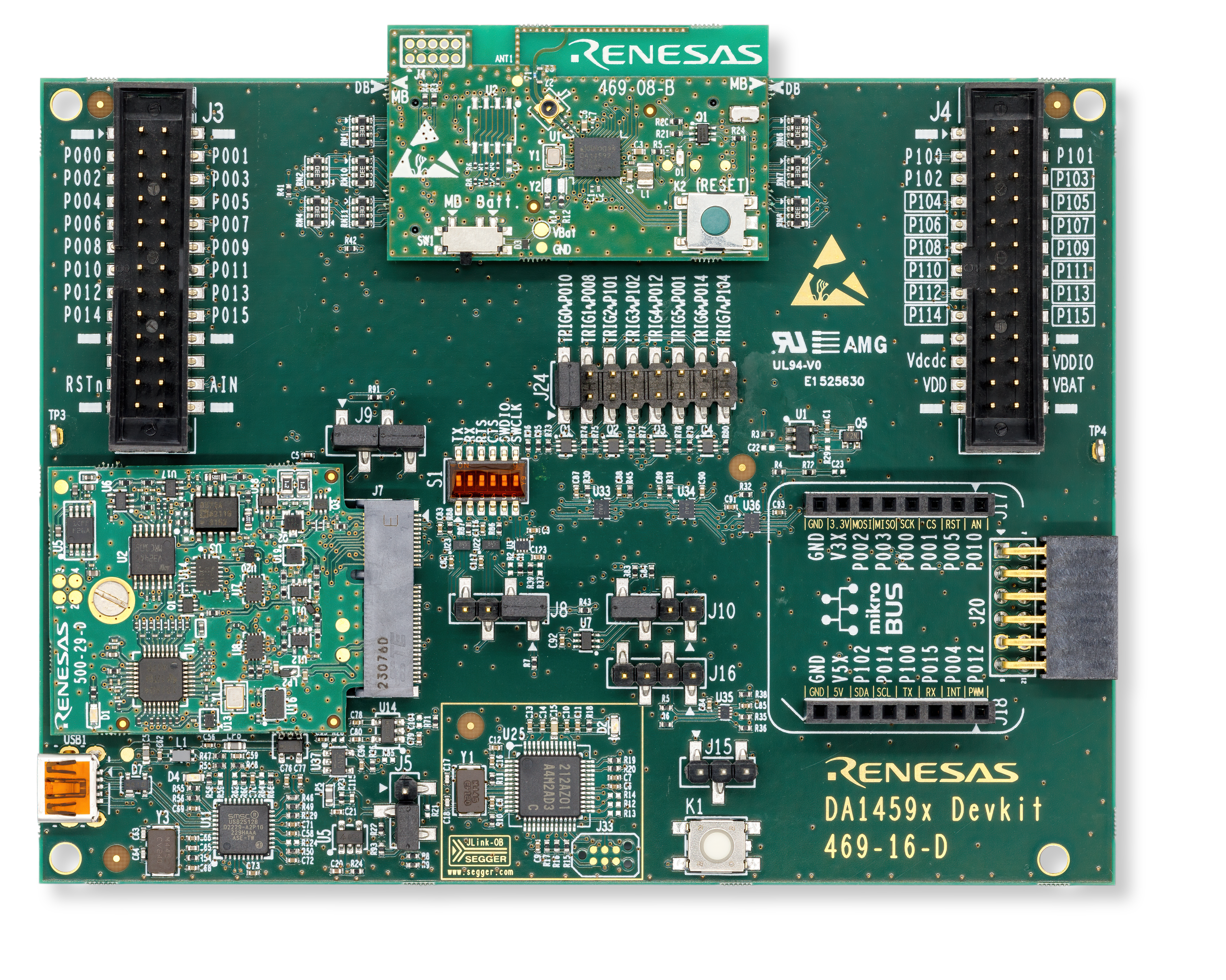
Figure 12 DA14594 development kit
1.3. How to use the tool
The firmware can either be selected from the online resources available via the tool or the user can browse through the hex or binary file from PC.
“Download online firmware” allows the user to take the binary from online resources. Some of the examples that are listed now are as shown in the figure below. As and when more software examples are added in the website the list can get updated by going to File -> Refresh online resources option in the tool.
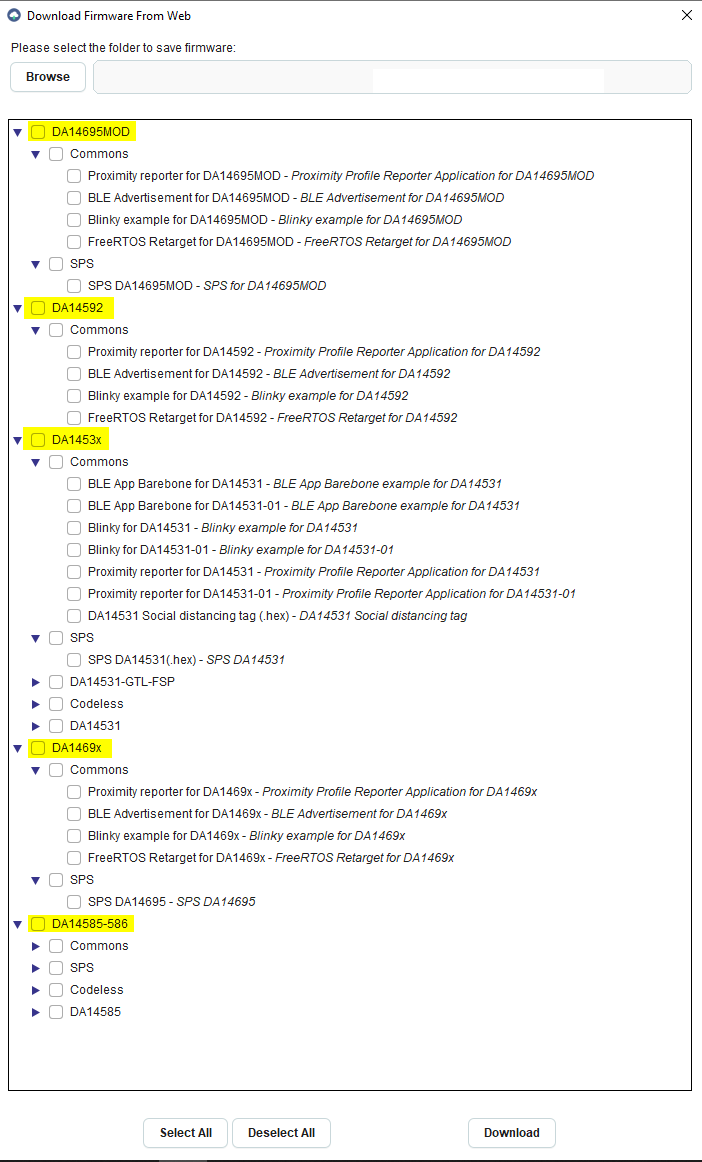
Figure 13 Renesas SmartBond™ Flash Programmer Tool
Select the firmware to be programmed to Flash and then click “Download” button. The message log would look something like this,
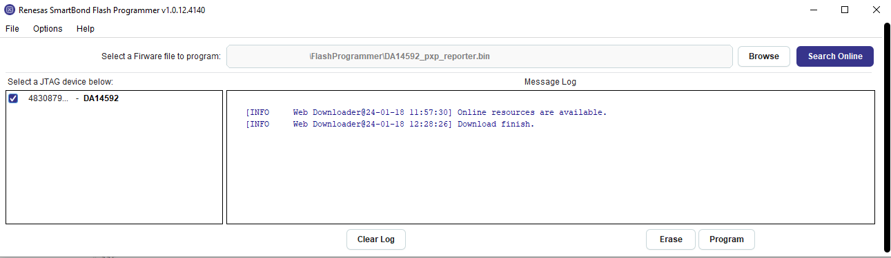
Figure 14 Selecting the firmware to program into flash
Select the JTAG serial number of the connected device and click on “Program” to program the Flash device. The message log would look something like this,
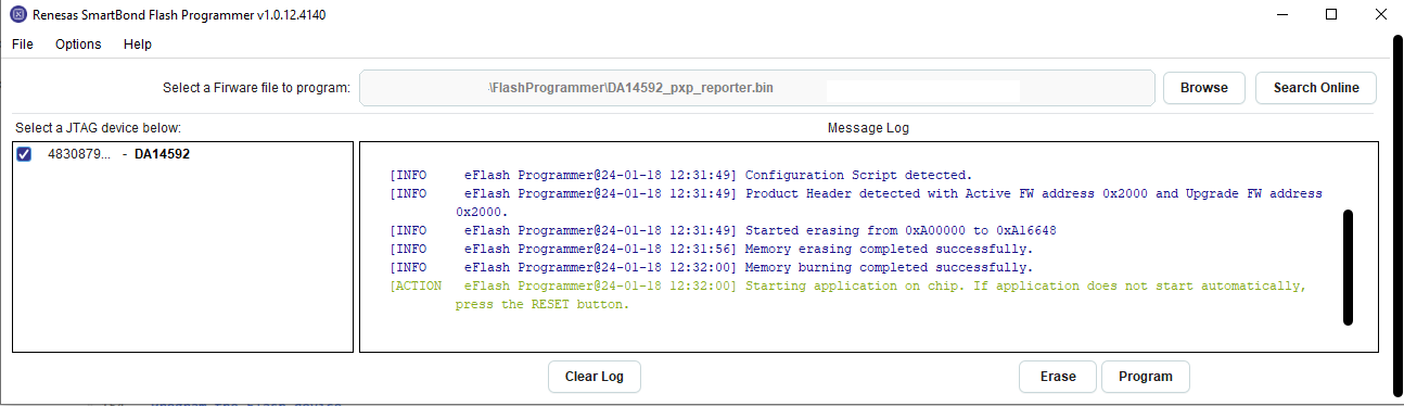
Figure 15 Program the Flash device
To erase the Flash, select the JTAG serial number of the connected device and select “Erase”. The message log would look something like this,
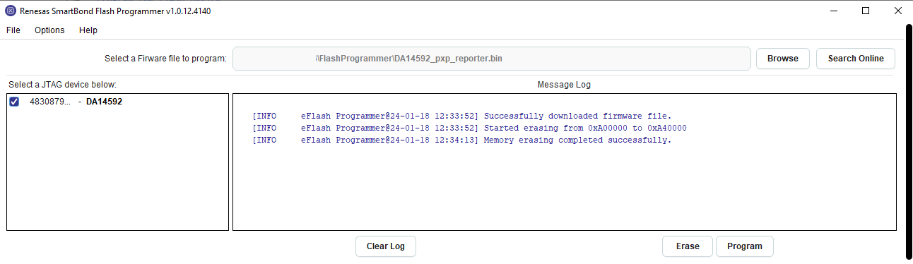
Figure 16 Erase the Flash device
The list of software examples and applications on the DA1453x and DA1458x based on the SDK6 can be found in SDK6 GitHub repo
The list of software examples and applications on the DA1469x based on the SDK10 can be found in SDK10 GitHub repo
The list of software examples and applications on the DA1459x based on the SDK10 can be found in SDK10_DA1459x GitHub repo