3. Pairing and bonding
This section provides an overview of activities in each pairing phase, focusing on the LE Legacy Pairing with Passkey Entry (PIN) use case. In LE Legacy Pairing, none of the methods safeguard against passive eavesdropping due to the use of predictable or easily established values for Temporary Key (TK) during pairing. However, if pairing information is distributed without an eavesdropper, all methods ensure confidentiality.
You can take a higher level look on the activities that take place during each pairing phase in the following figure:
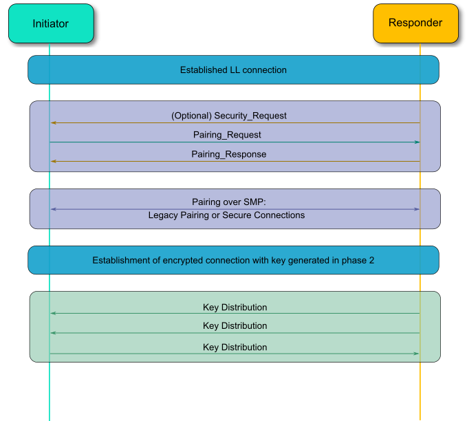
Figure 4 BLE pairing phases
3.1. Pairing
3.1.1. Pairing Phase 1: Feature exchange
The first step that has to be performed is to establish a connection between the devices. This can either be performed in band as usual or out of band. The Initiator then starts the Pairing Feature Exchange process by sending a Pairing Request. The responding device completes the Pairing Feature Exchange by responding with a Pairing Response command. It is also possible for the slave to initiate the pairing procedure by sending a Security Request to the master. In that case, the master will either start the pairing by initiating the same procedure as before, or it will reject it.
All Security Manager Protocol commands are sent over the Security Manager Channel which is an L2CAP fixed channel with CID 0x0006. Below you can see the general format of a Security Manager Protocol Packet.

Figure 5 Security Manager Protocol packet
The Pairing Request packet is composed of the following fields:
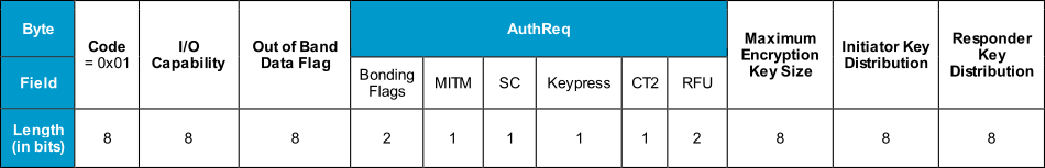
Figure 6 Pairing Request packet
Code: This distinguishes the command that is being used for the Security Manager Protocol and is 0x01 for the Pairing Request.
I/O Capability: This defines the I/O capabilities of the device as discussed in the previous section.
OOB data field: This field indicates if Out of Band data are already available to initiate an Out of Band pairing.
AuthReq: An 8-bit field that indicates the requested security properties.
Bonding Flags: A 2-bit field that shows the type of bonding being requested. Currently it can only be set to “Bonding” or “No Bonding”.
MITM: If the device is requesting MITM protection, this bit field has to be set. This enables authentication of the device.
SC: Stands for Secure Connections, and is set if the Secure Connections feature is supported. If LE Secure Connections pairing is supported by the device, then the SC field must be set to 1, otherwise it must be set to 0. If both devices support LE Secure Connections pairing, then LE Secure Connections pairing must be used, otherwise LE Legacy pairing will be used.
Keypress: Used only in the Passkey Entry protocol and it will be ignored by other protocols. When this field is set, keypress notifications will be used when entering the PIN. This will exchange the passkey one bit at a time, which is an important enhancement in Bluetooth 4.2 over the previous entry model (Bluetooth 4.1 or older), where the whole passkey is exchanged in a single confirm operation. This has enhanced the passkey exchange mechanism and now it is more difficult to predict the passkey in a MITM attack.
CT2: Indicates that a security function, called h7, is available for the encryption process.
RFU: Reserved for future use.
Maximum Encryption Key Size: Since different devices have distinct processing abilities, this byte indicates the maximum key size that the device can handle.It can be in the range of 7 to 16 octets.
Initiator Key Distribution: This field indicates which keys the initiator wants to generate and distribute in the subsequent phases.
Responder Key Distribution: Similar to the above, this field indicates which keys the initiator is requesting the responder to generate and distribute.
The Responder in turn will initiate a Pairing Response message, which is similar to the Pairing Request message. On success, the devices will start the Pairing Phase 2, in order to generate the Short Term Key and encrypt the link.
3.1.2. Pairing Phase 2: Short Term Key Generation
After a successful Pairing Feature Exchange, the two devices will start encrypting the link. In the Passkey Entry pairing method, a six-digit random number will be displayed on one device and the other device would have to input it. This passkey will be used as a Temporary Key (TK). If the Just Works association model will be used, then the TK will be set to zero.
There are also two more random numbers created, the Mrand on the master’s side, and the Srand on the slave’s side. Both of these are used to create a confirmation hash that each side has to validate.
- All of the LE legacy pairing methods use and generate two keys:
Temporary Key (TK), which is a 128-bit temporary key used in the pairing process which is used to generate the Short Term Key.
Short Term Key (STK) is a 128-bit temporary key used to encrypt a connection following pairing.
The procedure for LE legacy pairing with Passkey entry is depicted in the next figure:

Figure 7 Successful pairing in Legacy pairing with Passkey Entry
Using the random number that a device has generated, either Mrand or Srand, the confirmation hashes Mconfirm and Sconfirm will be calculated on each side.
These hashes are produced with the following fields:
Temporary Key
Random value, either Mrand or Srand
Pairing Request command
Pairing Response command
Initiating device address type
Initiating device address
Responding device address type
Responding device address
The devices exchange the calculated hashes using the Pairing Confirm commands. Then the master sends its random number, Mrand, with the Pairing Random command. The slave confirms the value using the Mrand, and then sends its own random number, Srand, to the master for confirmation.
If the initiating device’s calculated Sconfirm value matches the received Sconfirm value from the responding device, the initiating device calculates the STK and tells the Controller to enable encryption. At this point, the link can now be encrypted with the Short Term Key (STK), which will be derived from the TK, the Mrand, and the Srand. Security is initiated by the Security Manager in the device in the master role, but the slave device may request the master device to initiate pairing or other security procedures.
3.1.3. Pairing Phase 3: Transport specific key distribution
Key generation
Key generation in Bluetooth LE is performed by the Host on each LE device. By performing key generation in the Host, the key generation algorithms can be upgraded without the need to change the Controller.
The purpose of the key generation procedure in BLE is to provide the following features:
Confidentiality of data and device authentication.
Authentication of unencrypted data.
Device Identity.
LE security uses the following keys and values for encryption, signing, and random addressing:
Identity Resolving Key (IRK) is a 128-bit key used to generate and resolve random addresses.
Connection Signature Resolving Key (CSRK) is a 128-bit key used to sign data and verify signatures on the receiving device.
Long Term Key (LTK) is a 128-bit key used to generate the contributory session key for an encrypted connection.
Encrypted Diversifier (EDIV) is a 16-bit stored value used to identify the LTK distributed during LE legacy pairing. A new EDIV is generated each time a unique LTK is distributed.
Random Number (Rand) is a 64-bit stored valued used to identify the LTK distributed during LE legacy pairing. A new Rand is generated each time a unique LTK is distributed.
Confidentiality and device authentication is accomplished by encrypting the link and setting the MITM option to use the suitable pairing process. Authentication of unencrypted data is achieved at the ATT layer by using the key called Connection Signature Resolving Key (CSRK). The sending device signs the data with a 12-octet signature after the Data PDU and the receiving device verifies the signature to authenticate the other end. The Identity Resolving Key (IRK) is the key used to support a privacy feature of the LE specification that allows a device to use a random address that can be resolved. The IRK, in combination with a random value, is used to identify the device. If someone can’t have access to IRK, it is impossible to identify if the random address belongs to the same device.
LE legacy pairing is using all the above keys and values, whereas LE Secure Connections is only using the IRK, CSRK, and LTK. The EDIV and Rand are used by the slave device to establish a previously shared LTK in order to start an encrypted connection with a previously paired master device. The keys that will be distributed have been requested by each device during the Pairing Feature Exchange phase in the Initiator Key Distribution and Responder Key Distribution fields. You can see the field below:

Figure 8 LE key distribution format
The initiating device indicates to the responding device which transport specific keys it would like to send to the responding device and which keys it would like the responding device to send to the initiator. The responding device replies with the keys that the initiating device shall send and the keys that the responding device shall send. In the key distribution phase, the slave gives keys to the master so a reconnection can be encrypted, its random addresses can be resolved, or the master device can verify signed data from the slave.
The master may also provide keys to the slave device so a reconnection can be encrypted if the roles are reversed, the master’s random addresses can be resolved, or the slave can verify signed data from the master. In LE legacy pairing:
If the EncKey bit is set, then the device will generate/request the LTK using the Encryption Information command, followed by EDIV and Rand using the Master Identification command.
If the IdKey bit is set, then the device will generate/request the IRK using the Identity Information command, followed by its public device or static random address using the Identity Address Information command.
If the SignKey bit is set, then the device shall distribute the CSRK using the signing information command.
The IRK and CSRK will be explained in detail in the next tutorial. To distribute the LTK and other keys in Pairing Phase 3, an encrypted session using the STK must have been established. A device may request encrypted session setup to use the LTK, EDIV, and Rand values distributed by the slave device when the key distribution phase has completed; however, this does not provide any additional security benefit. If an attacker has established the distributed LTK value then performing encrypted session setup to use the distributed values does not provide any protection against that attacker.

Figure 9 Transport specific key distribution phase
3.2. Bonding
Bonding allows two connected devices to exchange and store security and identity information to create a trusted relationship. There are two modes for bonding, non-bondable mode and bondable mode, as we saw earlier in the pairing process. Bonding may only occur between two devices in bondable mode. When a bond has been created, each device stores the distributed peer keys and uses this information in next connections requests, and in this fashion the pairing process can be skipped, which results in energy savings and reduces the time a user must wait to operate their device.
The LTKs are stored in a security database and they are identified by the EDIV and Rand values. When a bond has been performed, every subsequent reconnection will use the LTK that has been distributed to encrypt the link.

Figure 10 The bonding procedure