5. Running The Demonstration Example
This section describes the steps required to prepare the Pro DevKit and other tools to successfully run the example code. A serial terminal and optionally a frequency meter or an oscilloscope are required for testing and verifying the code. For information on configuring a serial terminal, as well as a Pro DevKit, read the Starting a Project tutorial.
5.1. Measuring the LP Clock Frequency
This demonstration example gives the developer the ability to measure the selected lp clock by using either a frequency meter or an
oscilloscope. The lp clock pulses can be selected from P3.0 pin on Pro DevKit, which by default is disabled. To do so,
TEST_LP_CLOCK_OUTPUT in main.c should be set to ‘1’. Please note that this feature is intended only
for debugging purposes. Fig. 11 illustrates the frequency of the selected XTAL32K lp clock, as measured using a digital
frequency meter.
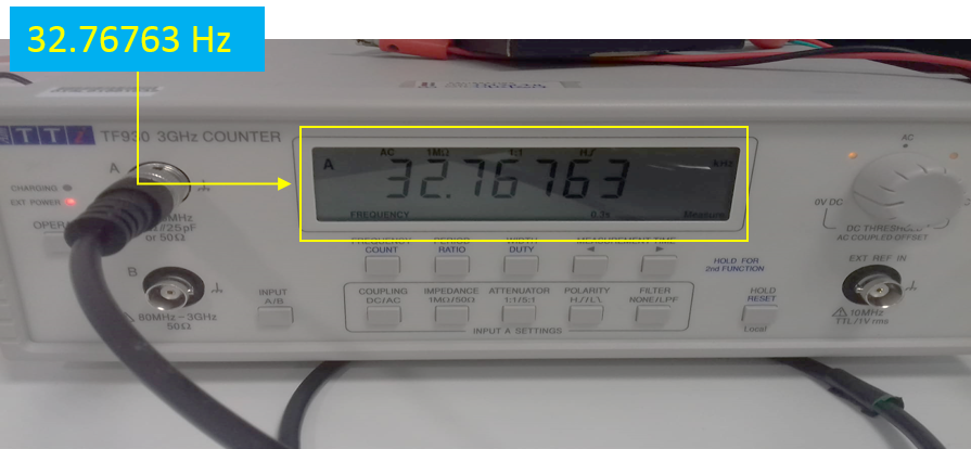
Fig. 11 Measuring the LP Clock Period
Warning
In order for the RTC measurements to be as accurate as possible, the measured frequency should be as close as possible to the expected one (for the external crystal, this is 32768 Hz). It is possible to change the pin on which the lp clock is measured, however, pins P1.0, P1.5, and P1.7 might affect radio performance if toggled while there is RF activity. Therefore, it is recommended to use them at low speed and not while radio is active.
5.2. Configuring The Demo Code
- Establish a connection between the target device and your PC through the USB2(DBG) port of the motherboard. This port is used both for powering and communicating with the DA1468x SoC. For this demonstration, a Pro DevKit is used.
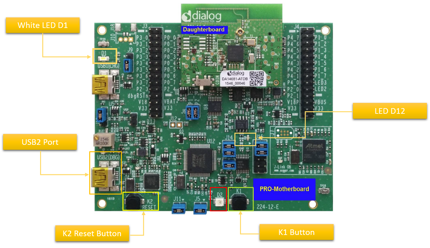
Fig. 12 DA1468x Pro DevKit
- Import and then make a copy of the freertos_retarget sample code found in the SDK of the DA1468x family of devices.
Note
It is essential to import the folder named scripts to perform various operations (including building, debugging, and downloading)
- In the target application, add/modify all the required code blocks as illustrated in the Code Overview section.
Note
It is possible for the defined macros not to be taken into consideration instantly. Hence, resulting in errors during compile time. If this is the case, the easiest way to deal with the issue is to: right-click on the application folder, select Index > Rebuild and then Index > Freshen All Files.
- In
sw_rtc_task.c, declare time parameters of your choice. These values will be the starting point for all of the subsequent RTC operations.
 /*
  * Declare date/time with preferred values.
  */
__RETAINED_RW sw_rtc_date_time_t date_time = {
        /* Declare all the info related to date.
         *
         * \note: The weekday is calculated automatically by the code.
         *
         * \note: The code performs sanity checks to identify values that are out of the allowable boundaries.
         *        For any invalid value, the code gets stuck in assertions!
         *
         */
        .date = {
                .year       = 2018,
                .month      = 8,
                .month_date = 6,
        },
        /*
         * Declare all the info related to time.
         *
         * \note: maximum time resolution is microseconds (us) */
        .time = {
                .hour = 0,
                .min  = 0,
                .sec  = 0,
        }
};
- Optionally, enable/disable debugging messages on the serial console (enabled by default):
#define SW_RTC_DBG_MESSAGES_CONSOLE 1
- In
alert_task.c, declare alert parameters of your choice:
/*
 * Declare parameters for the alert events.
 *
 * \note: There are three distinct alert classes which can be enabled-disabled-configured individually.
 *
 */
__RETAINED_RW time_alert_t my_alert = {
        .hour     = 4,   // Set alerts expressed in hours   (every x hours).
        .min      = 2,   // Set alerts expressed in minutes (every x minutes).
        .sec      = 5,   // Set alerts expressed in seconds (every x seconds).

        .repeat_h = false,  // If set to false, alerts (expressed in hours)   are triggered only once.
        .repeat_m = true,   // If set to false, alerts (expressed in seconds) are triggered only once.
        .repeat_s = false,  // If set to false, alerts (expressed in seconds) are triggered only once.
};
- Optionally, enable debugging messages on the serial console (enabled by default):
#define TIME_ALERT_DBG_MESSAGES_CONSOLE 1
- Users may also enable the breath timer and the white LED1 of the chip (disabled by default):
#define TIME_ALERT_BREATH_TIMER_EN 0
- Build the project in either Debug_QSPI or Release_QSPI mode and burn the generated image to the chip (either via the serial or jtag port).
- Press the K2 button on Pro DevKit to reset the device. This is required in order for the chip to start executing its firmware.
5.3. Verifying The Demo Code
- Press the K1 button on Pro DevKit. If enabled, a debugging message is displayed on the console indicating the current date and time.
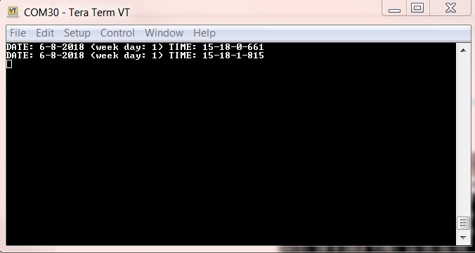
Fig. 13 Debugging Messages Indicating the Current Date and Time.
- Upon an alert event and given that debugging messages have been enabled, a message will be displayed on the serial console indicating the source of the alert. If breath timer has also been enabled, then the white LED1 on Pro DevKit will start blinking. At any time, it can be disabled by pressing the K1 button.
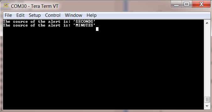
Fig. 14 Debugging Messages Indicating the Alert Source