4. Running The Demonstration Example
This section describes the steps required to prepare the Pro DevKit and other tools to successfully run the example code. A serial terminal, a breadboard, a few jumper wires, a potentiometer, and a coin cell battery are required for testing and verifying the code. If you are not familiar with the recommended process on how to clone a project or configure a serial terminal, read the Starting a Project tutorial.
4.1. Verifying with a Serial Terminal
- Establish a connection between the target device and your PC through the USB2(DBG) port of the motherboard. This port is used both for powering and communicating to the DA1468x SoC. For this tutorial a Pro DevKit is used.
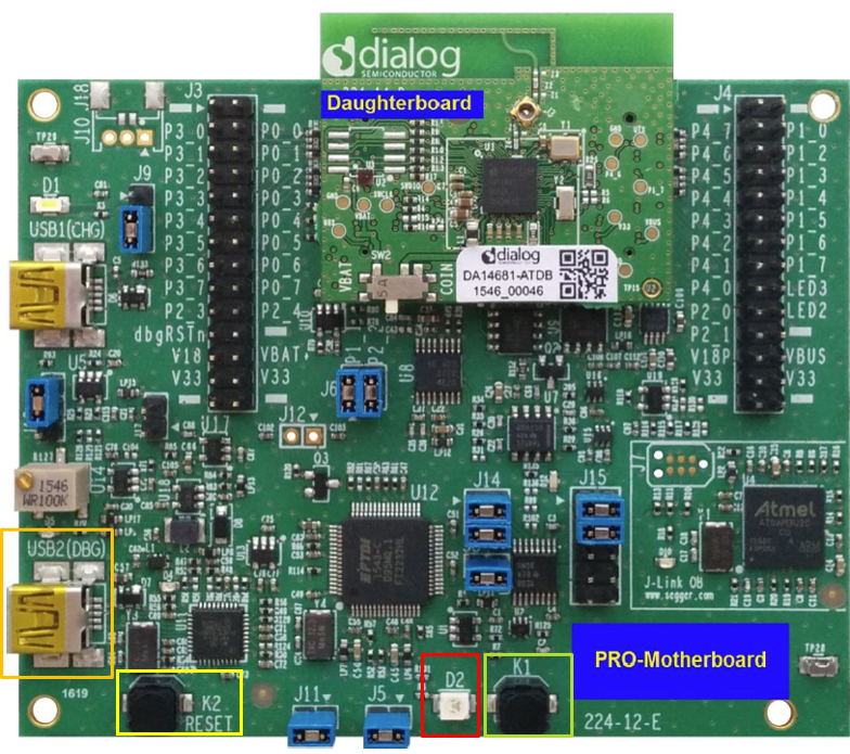
Fig. 14 DA1468x Pro DevKit
- Import and then make a copy of the freertos_retarget sample code found in the SDK of the DA1468x family of devices.
Note
It is essential to import the folder named scripts to perform various operations (including building, debugging, and downloading).
- In the newly created project, create a new
platform_devices.hheader file under the project’s/configfolder. To do this:- Right-click on the
/sdk/adapters/include/platform_devices.hheader file (1) and select Copy (2).
- Right-click on the
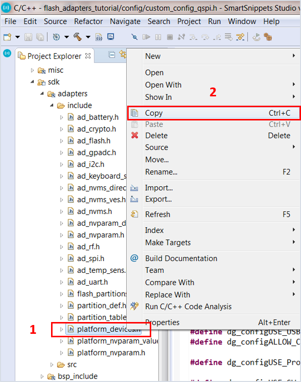
Fig. 15 Creating platform_devices.h Header File, Step 1
- Right-click on the
/configfolder (3) and select Paste (4).
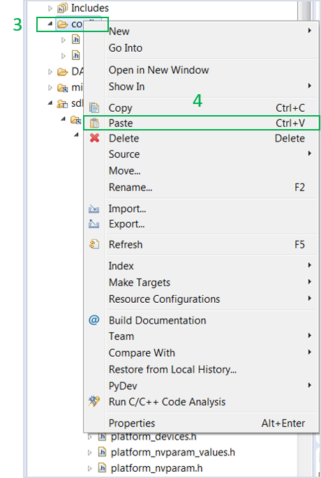
Fig. 16 Creating platform_devices.h Header File, Step 2
Note
If a new platform_devices.h file is not created in the /config directory,
the application will inherit the default macro definitions from /sdk/adapters/include/platform_devices.h.
- In the target application, add/modify all the required code blocks as illustrated in the Code Overview section.
Note
It is possible for the defined macros not to be taken into consideration instantly. Hence, resulting in errors during compile time. If this is the case, the easiest way to deal with the issue is to: right-click on the application folder, select Index > Rebuild and then Index > Freshen All Files.
- Build the project either in Debug_QSPI or Release_QSPI mode and burn the generated image to the chip.
- Insert the coin cell battery (either rechargeable or non-rechargeable) in the daughterboard’s battery holder.
- For this demonstration, a typical CR2023 non-rechargeable coin cell battery has been selected. The battery is placed at the bottom of the daughterboard in the dedicated battery holder as illustrated in Fig. 17. The battery is inserted by first sliding it under the metallic clip of the battery holder. Extra attention is needed when removing the coin cell battery from its holder, if this is not done properly then the plastic battery holder can be subject to breaking.
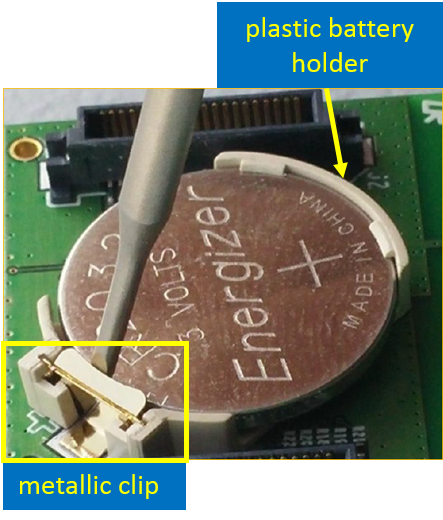
Fig. 17 Rear View of the DA1468x Daughterboard
- Select the power supply source through switch SW2. Power supply selection is available between the motherboard and the coin cell battery, thus allowing the daughterboard to operate as a standalone device once programmed. For this tutorial, the position of the SW2 switch does not matter.
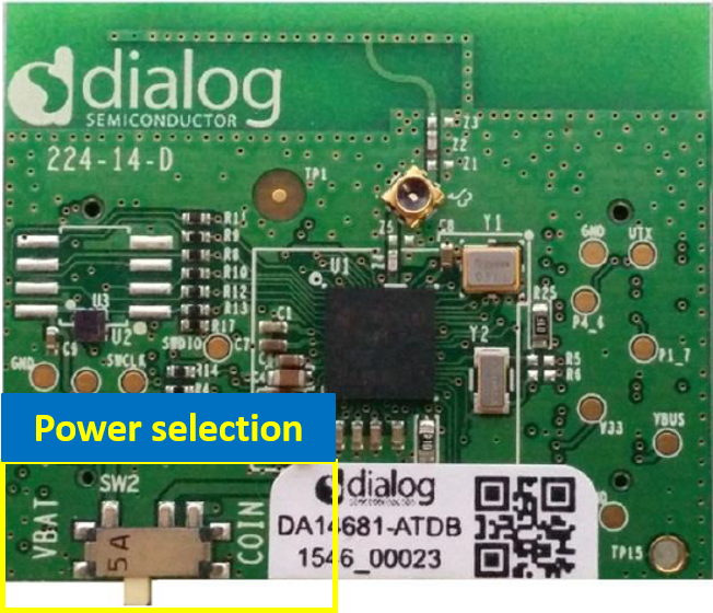
Fig. 18 Power Supply Selection
- Connect the potentiometer to the Pro DevKit as illustrated in Fig. 19. For this demonstration, a simple 3-terminal potmeter has been selected. Two terminals are connected to the main power source, that is 3.3 V and GND, and the third to the selected ADC pin on Pro DevKit, that is P1_2.
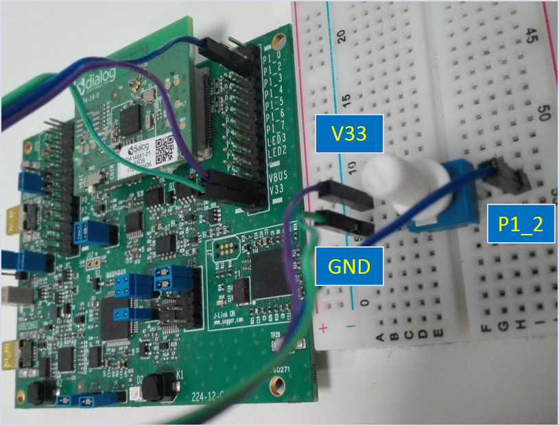
Fig. 19 Snapshot of the Potmeter Connected to Pro DevKit
- Open a serial terminal (115200, 8-N-1) and press the K2 button on Pro DevKit. This step starts the chip executing its firmware.
- Change the input voltage level of the P1_2 pin (set as a GPADC pin) by rotating the potentiometer position both right and left. Observe the resulting analog-to-digital measurements on the console (1). Results should be updated every 1 second.
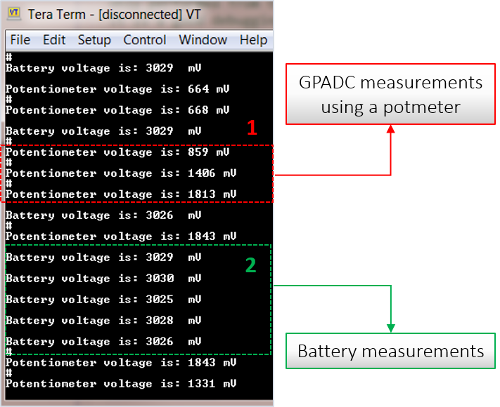
Fig. 20 Debugging Messages for the Various Analog-to-Digital Operations
- Press the K1 button on Pro DevKit. A battery measurement is triggered and the result of the analog-to-digital conversion is printed out on the console (2).