NFC IoT Tuner-7.1.0-df379d22 User Manual
This is the online user manual for the software “NFC IoT Tuner” version 7.1.0. NFC IoT Tuner can be used to generate configuration data for the PTX105R. The software can be used without any additional hardware attached. A part of the NFC IoT Tuner software are test applications which can be started from the NFC IoT Tuner user interface. These test applications may require hardware access (USB ports for example).
This user manual is provided in English only. For assistance in other languages please contact your local Renesas Electronics Corp. representative.
Features
The software supports the following platforms and operating systems:
Windows 11 x86 64-bit
Ubuntu 22.04 LTS x86 64-bit
This document is valid for all these platforms, platforms specific information is explicitly highlighted.
Current NFC IoT Tuner version supports following hardware:
WS004-NFCShield-PoCZ PTX105R Arduino Shield Rev A
Panthronics Eval_Board_PTX105R v1.0
PTX100R EB v1.4
PTX130R-EB-ST v1.1
The main application features are:
Power configuration
NFC polling configuration
IOT discovery application
NDEF read/write application
HCE T4T application
Q-measurement application
Temperature calibration
Installation Notes
NFC IoT Tuner release package is distributed as a zip archive. To extract the content of the package open the Windows explorer, right-click file named NFC_IoT_Tuner_v7.1.0.zip and select Extract All… from the list. In the windows that pops up press the Extract button and the content of the archive will be extracted to a specified folder.
There should be following content present in the archive:
LINUX-x86-64Bit folder : The application for Ubuntu 21.10 (x86) 64-bit (minimal installation)
WINDOWS-x86-64Bit zip archive : The application for Windows 10 (x86) 64-bit
Installation on Linux
An AppImage package can start a NFC IoT Tuner application without any installation on a LINUX distribution.
download the NFC IoT Tuner from the customer support portal
extract the zip archive
set the execute flag of the AppImage file
start the AppImage file
# starting first time
mkdir my_appimage
unzip <zip archive> -d my_appimage
cd my_appimage
chmod +x <AppImage file>
./<AppImage file>
# starting next time
./<AppImage file>
Starting the AppImage for the first time you must agree to displayed license terms.
Installation on Windows
The following step-by-step instruction will guide you through the software installation procedure.
Double-click the installer executable in the Windows Explorer
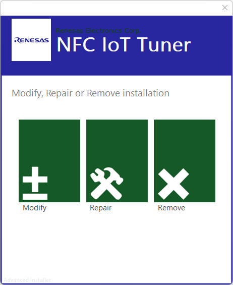
In case a previous version of NFC IoT Tuner is installed on your system it can be required to uninstall that version first, if you don’t see a windows as shown in the figure below skip the next step and proceed with step 5
Press the Remove button and in the confirmation page press again the Remove button
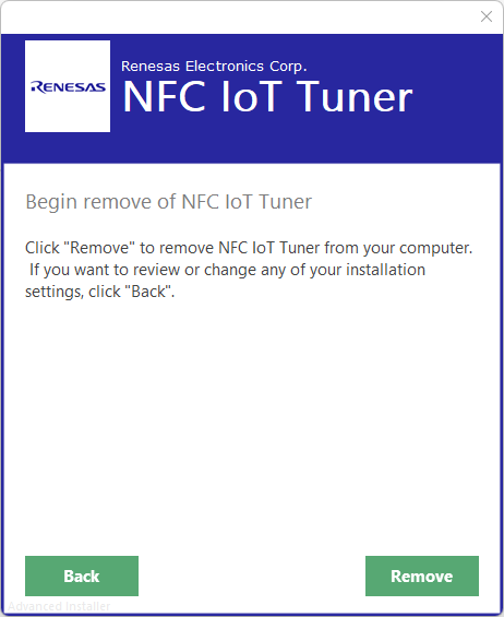
Once the removal operation succeeded confirm by pressing the Finish button and re-start with step 1
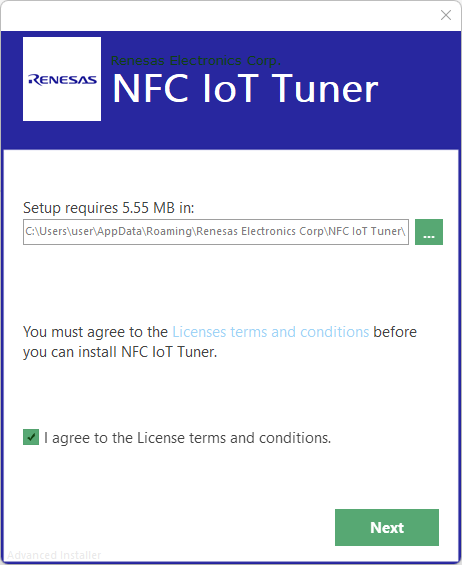
Click the box left to the text “I agree to the License terms and conditions” as shown in the figure below and press the Next button afterwards
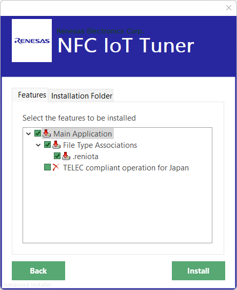
Press the INSTALL button to start the installation. You might optionally exclude the file association feature from the installation by clicking on the “File Type Associations” checkbox. In case the product shall be used for Japanese market enable the feature “TELEC compliant operation for Japan” by clicking on the corresponding checkbox (for compliance reasons certain features will not be available when using that option).
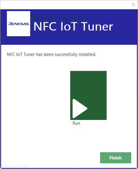
Press the Run button to start the NFC IoT Tuner application, the installer windows will close automatically
Graphical User Interface
To start NFC IoT Tuner on Windows, double-click the shortcut called “NFC IoT Tuner” on your desktop. A user interfaces as shown in the figure below will be displayed.
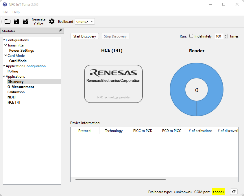
The menu bar offers access to different operations such as loading a configuration from a file or opening the offline user manual. The following sections explain the specific operations in more detail.
Under the “Modules” it’s possible to choose different configuration and measurement views.
Toolbar
The application toolbar is located right below the menu bar. Using the toolbar buttons provides quick access to the actions available via the File and Edit menus. In addition, the toolbar allows configuring the serial port used for all features of the application which require hardware access.
The screenshot below shows the content of the toolbar including a serial port selection box for the “Evalboard” device. Note that depending on the NFC IoT Tuner version the supported devices and therefore the label beside the drop-down serial port selection can differ. It will refer to an equally named Renesas Electronics Corp. hardware device. In case operation of multiple devices is supported for a NFC IoT Tuner version there will be multiple drop-down serial port selections available.

To select the serial port for a connected PTX device, click the drop-down list to select the matching port identifier. The serial port is opened/closed every time access to a PTX device is required.
Settings … configuration view
In the File menu click the Settings … entry to open the application settings dialog window.

Set shutdown temperature
The NFC SDK uses the shutdown temperature, a chip-specific binary value, which can be measured using the Calibration application.
It is possible here to override the default value by checking the checkbox and specifying the number in the Setting field. If the checkbox is unchecked, the application will use the default configuration.
Changes made to this block become effective on the next application start.
Transmitter - Power Settings configuration view
Under Modules select the Configurations/Transmitter/Power Settings entry to open the transmitter configuration view.
This view allows selection of the wave amplitude for the transmission power. The slider control called “CW” (Continuous Wave) can be used to set the sine wave amplitude for the CW wavebank. The CW wavebank is a hardware unit responsible for generating a sine wave signal on the power amplifier output stage of the device.
Card Mode configuration view
Under Modules select the Card Mode/Card Mode entry to open the card mode configuration view.
This view allows selection of the wave amplitude for the transmission power. The slider control called “CM” (Card Mode) can be used to set the sine wave amplitude for the CM wavebank. The CM wavebank is a hardware unit responsible for generating a sine wave signal on the power amplifier output stage of the device.
Settings configurable in this view are used in case the application polling configuration “Card mode (HCE T4T) is enabled.
Applications
Polling application configuration view
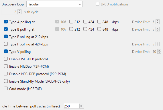
Under Modules select the Application configuration -> Polling entry. In the window pane a screen as shown in the figure below should appear.
 {style=”width:50%;border:1px solid black;”}
Use this module to generate the initialization code for the discovery initialization of the SDK.
The discovery loop setting allows to configure the general polling loop behavior. Setting Regular will configure the NFC to poll for the selected technologies in an interval as defined by the Idle time between polling setting. Setting Reduced-Power will let the NFC perform LPCD polling as defined in the LPCD Settings view. Once an object in proximity has been detected by LPCD the NFC will switch to regular polling. Setting Reduced-Power every n-th cycle will perform LPCD polling but will cause the NFC do to a regular polling every n-th time. It is recommended if a reduced power mode is selected that also the Stand-By mode should be enabled.
Press Copy to clipboard to copy the generated code to clipboard.
Configuration from this view is used by [Discovery] application, described below.
Type F polling bitrates are mutually exclusive, so it’s possible to choose either 212kbps or 424kbps, but not both.
For Type A and B polling, multiple communication speeds are available. By default, both types are configured to communicate at 106kbps. Multiple speeds can be selected for each type but the NFC is responsible to select the highest speed supported by the card.
Checking the LPCD Notifications checkbox will lead to a periodical request of the LPCD notification counter in the Discovery Application and display the result in the status bar. This shows the number of wake-ups happened before a successful activation. This information is useful to prove if the LPCD settings are configured correctly. The counter stops counting at 255. This feature works with an Idle Time value greater than 0 only.
Discovery application view
Under Modules select the Measurements -> Discovery entry. In the window pane a screen as shown in the figure below should appear.
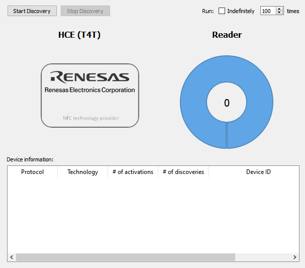
Use this module to start IOT discovery loop. “Start Discovery” will start the discovery loop and “Stop Discovery” will stop the discovery loop. The discovery loop may be combined with card emulation, that can be enabled in the polling configuration.
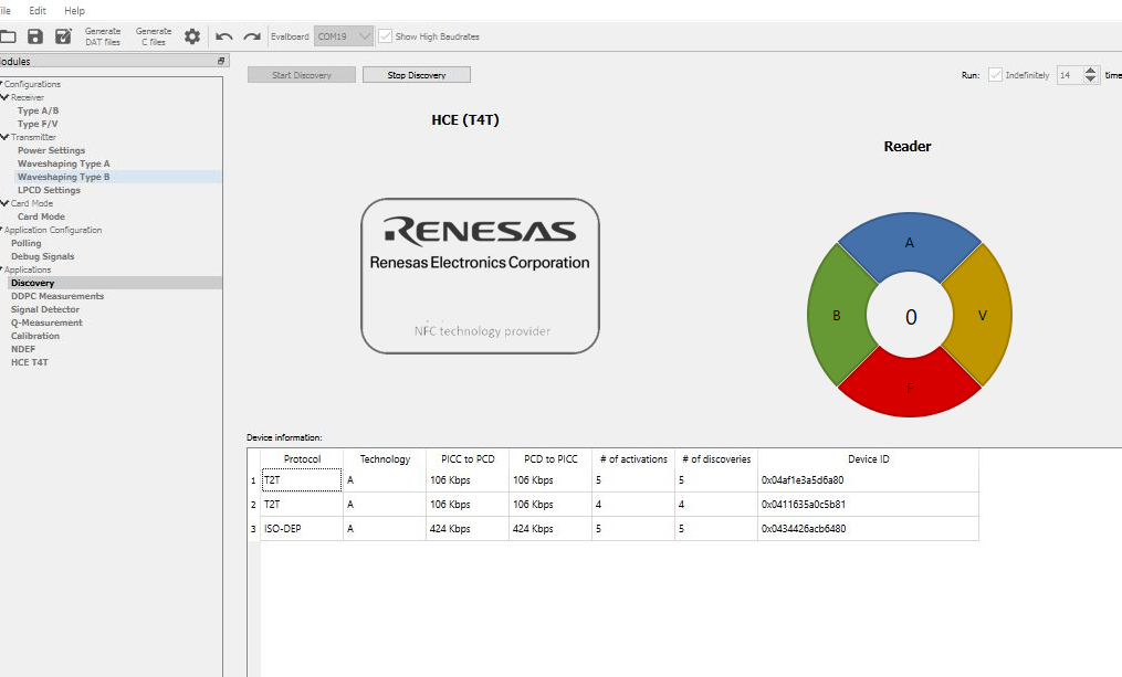
While discovery is active the view will display information on the PICC’s detected- their technology, protocol and unique ID’s.
Pie chart will display the type of tags for which discovery is enabled.
If the card uses random generated ID’s, then each detection will create new line in detection table!
If the Card emulation (Card mode) is enabled, the card symbol will be shown in blue, otherwise gray. Also, the card size will change dynamically during communication to indicate activity.
Run loop x times feature allows to either run discovery for a certain number of discoveries or indefinitely. Only completed discoveries will be counted as a single discovery. If no cards are detected, it’s not counted as completed discovery loop. For every completed loop first 1 or more PICC’s are discovered and # of discoveries in statistics table are updated, discovered PICC or first one in case of multiple PICC’s is activated, data is read and, for selected PICC, # of activations is updated in statistics table. Afterwards polling loop is restarted.
This application uses a serial port connected which can be selected in the toolbar. Please connect the hardware to the host system and press the Start Discovery button afterwards.
Temperature and current limit violation
Running the Discovery application enables the safety features of the NFC.
In case on of the following events happen the application will stop autonomously:
Current limit violation
Shutdown temperature reached
In case the driver current is limited by the overcurrent protection block (but not yet reached the overcurrent limit) the user is informed by a blinking red status bar text “Current limiting active”.
Q-Measurement application view
Please note that this application works independently from the Configuration views (means that any configuration made in these views has no effect to the measurement).
Under Modules select the Q-Measurement entry. In the windowpane, a screen as shown in the figure below should appear.
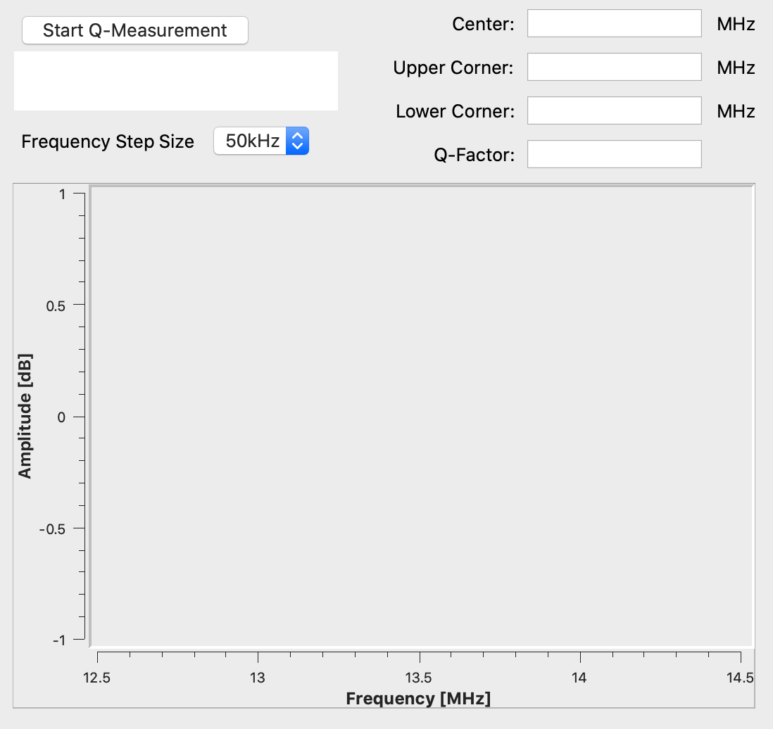
The application will trigger measurements for the frequency range between 12.46MHz and 14.76 MHz. Depending on the chosen frequency step width the application may run for some minutes.
When all measurements are finished, the following results will be displayed:
Center frequency
Lower corner frequency
Upper corner frequency
Q-Factor
In case the measurement fails a message box will display the reason for the failure. The measurement may sweep all frequencies successfully, but the maximum amplitude cannot be determined. In this case the error message “Could not find correct frequency responses and calculate Q-factor!” will be shown.
Select Poller device serial port connection in applications toolbar.
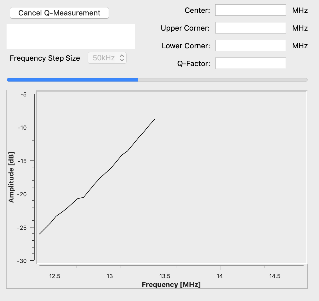
Connect the hardware to the host system and press the Start Q-Measurement button afterwards.
The Q-Measurement will start and display its current progress is shown at the progress bar. During the measurement for every single frequency measured the plot in the bottom area of the Q-Measurement view will be updated. A running measurement can be aborted by pressing the Cancel Q-Measurement button.
Temperature Calibration application view
Under Modules select the Temperature Calibration entry. In the windowpane, a screen as shown in the figure below should appear.
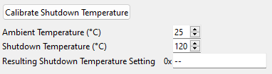
Shutdown temperature calibration is used to retrieve the chip shutdown temperature value used by NFC SDK. This value is a binary number for the chip only.
The Ambient Temperature and the Shutdown Temperature are the input parameters (in Celsius) to be adjusted according to user requirements. Start Temperature Calibration will start the process, which takes about a second to finish. If the process has been completed successfully, the resulting chip-specific temperature value can be read out from the Resulting Shutdown Temperature Setting entry. This value may optionally be set in the user settings dialog to override the default configuration (E8).
Please note, changes in the default shutdown temperature settings will become effective after restarting the application
PTX105R Arduino Shield for Arduino Uno R4
In order to use the PTX105R Arduino shield for the Arduino Uno R4 with the application, the PTX Tunneling Library is required. The example sketch PTX105R_Tunneling.ino must be downloaded to the Arduino board using the Arduino IDE. In NFC IoT Tuner Settings -> Enable tunneling mode must be disabled.
License information
The End-User License Agreement (“EULA”) for this software is shown when running the installation of the software. Besides that the EULA can be found next to the application’s executables in the folder specified by the user when installing.
This software prominently states any usage of 3rd-party open source libraries in the application’s about box (Help | About).
This program uses Qt cross-platform application and UI framework licensed under LPGL. On each supported platform this program dynamically links to the Qt libraries which has been build from the unmodified Qt Source Code as provided by the Qt Company (git://code.qt.io/qt/qt5.git). Qt’s license provisions require to provide a written offer with instructions on how to get the source code. In case you have any trouble downloading the Qt Source Code from the official links provided above, makes hereby a written offer to provide such source code to you. To make a Qt source code request, send email to the following address: mailto:.
Qt’s license provisions require to notify about LGPL licensed software is used by this program. The full text of the LGPL licenses can be obtained from the application’s installation folder.
nlohmann_json
This software uses the nlohmann_json library licensed under the MIT License as listed below.
MIT License
Copyright (c) 2013-2022 Niels Lohmann
Permission is hereby granted, free of charge, to any person obtaining a copy of this software and associated documentation files (the “Software”), to deal in the Software without restriction, including without limitation the rights to use, copy, modify, merge, publish, distribute, sublicense, and/or sell copies of the Software, and to permit persons to whom the Software is furnished to do so, subject to the following conditions:
The above copyright notice and this permission notice shall be included in all copies or substantial portions of the Software.
THE SOFTWARE IS PROVIDED “AS IS”, WITHOUT WARRANTY OF ANY KIND, EXPRESS OR IMPLIED, INCLUDING BUT NOT LIMITED TO THE WARRANTIES OF MERCHANTABILITY, FITNESS FOR A PARTICULAR PURPOSE AND NONINFRINGEMENT. IN NO EVENT SHALL THE AUTHORS OR COPYRIGHT HOLDERS BE LIABLE FOR ANY CLAIM, DAMAGES OR OTHER LIABILITY, WHETHER IN AN ACTION OF CONTRACT, TORT OR OTHERWISE, ARISING FROM, OUT OF OR IN CONNECTION WITH THE SOFTWARE OR THE USE OR OTHER DEALINGS IN THE SOFTWARE.