3. Analyzing The Demonstration Example
This section analyzes an application example which demonstrates using the GPADC adapters. The example is based on the freertos_retarget sample code found in the SDK. It adds one additional freeRTOS task which is responsible for performing analog-to-digital measurements on a dedicated pin on Pro DevKit (P0_25). The code also enables the wake-up timer for handling external events. Both synchronous and asynchronous GPADC operations are demonstrated.
3.1. Application Structure
The key goal of this demonstration is for the device to perform a few GPADC operations following an event. For demonstration purposes the K1 button on the Pro DevKit has been configured as a wake-up pin. For more detailed information on how to configure and set a pin for handling external events, read the External Interruption tutorial. At each external event, produced at every K1 button press, a dedicated callback function named
wkup_cb()is triggered. In this function, a freeRTOS signal namedsignal_potis sent towards theprvGPADCTask_POTapplication task to unblock its execution.
Depending on the value of the
POT_ASYNC_ENmacro, a synchronous or an asynchronous GPADC operation is performed. At the end of the measurement, the raw ADC value is converted into millivolt (mV) and a debugging message with the converted data is sent to the serial console.
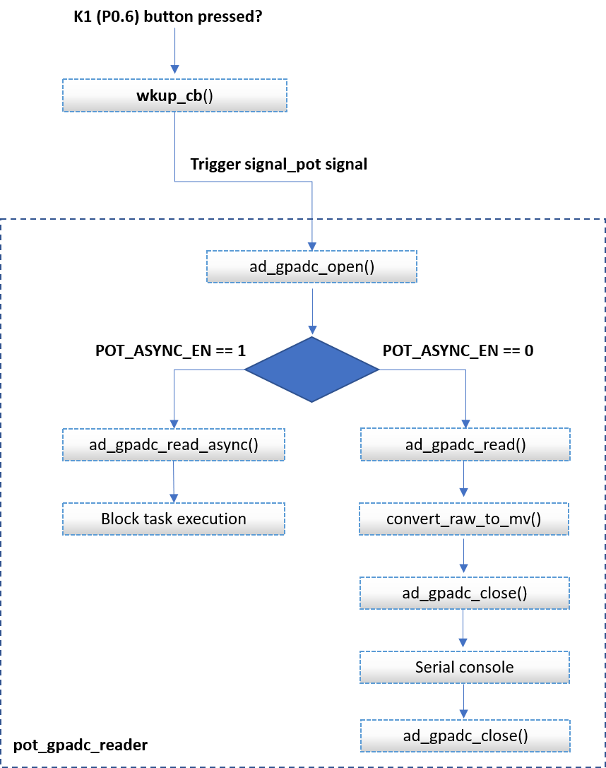
Figure 5 GPADC Conversions SW FSM - Main Execution Path
It is essential that developers must not call asynchronous related APIs without guaranteeing that the previous asynchronous transaction is finished. To ensure this, after triggering an asynchronous GPADC operation, the calling task blocks its execution until the arrival of a freeRTOS signal, indicating the end of the current GPADC operation.
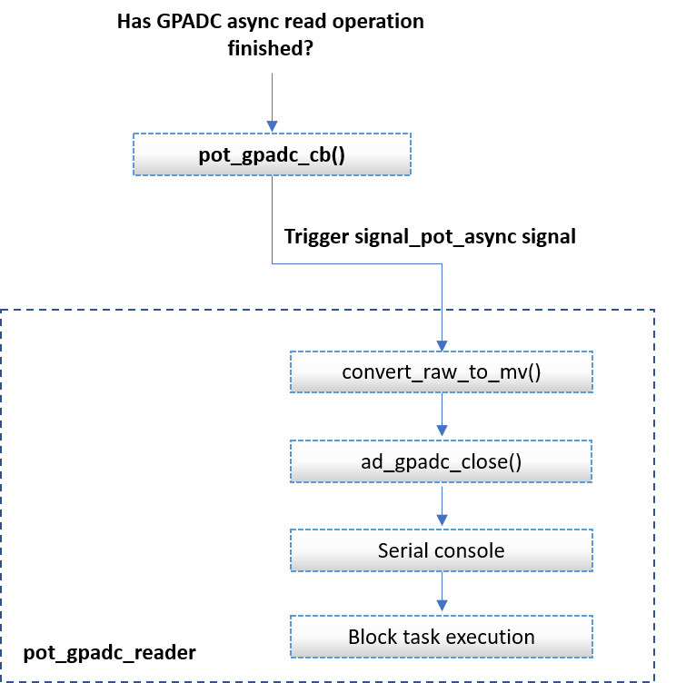
Figure 6 GPADC Async Conversions SW FSM - Callback Function Execution Path