4. Running The Demonstration Example
This section describes the steps required to prepare the Pro DevKit and other tools to successfully run an example code that is based on freertos_retarget sample code found in the SDK (demonstrates using the UART functionality).
To make things more interesting, let’s give some extra functionality to the device making the LED D2 on Pro DevKit to toggle after pressing a push button. The Wakeup controller can be programmed to wake up the DA1468x family of devices from a power-down mode after a pre-programmed number of GPIO events. In summary, this module consists of an event counter and a timer that counts every 1 ms. If the event counter reaches its pre-defined value, the counter is reset and an interrupt is generated. Each of the GPIO inputs can be selected to generate an interrupt event. As far as the timer is concerned, this hardware block can add a delay until an event (Key Hit) is being considered valid. This feature works as follow: upon an event the timer starts counting-down from its pre-defined value and, if it reaches zero and the Key hit is still valid, then the event counter is incremented. This feature is useful when using mechanical parts to trigger the controller by eliminating debouncing issues.
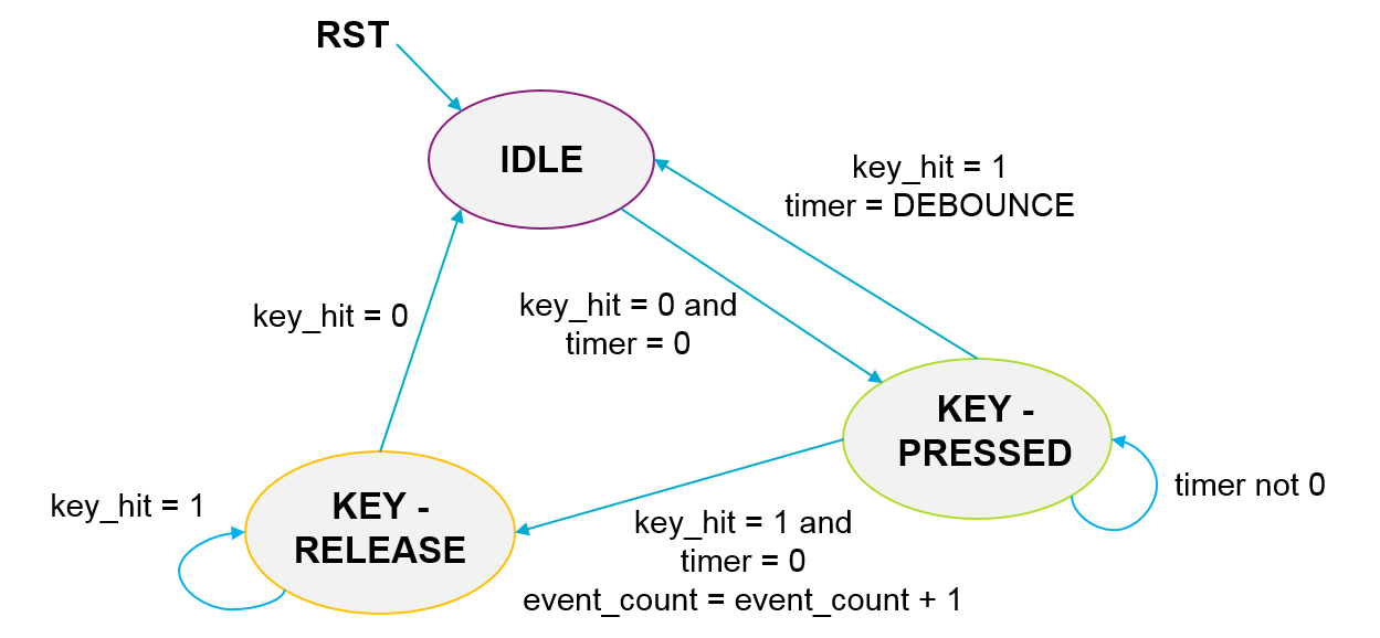
Fig. 16 Event Counter State Machine for the Wake-Up Interrupt Generator
Note
The event counter is edge sensitive. After detecting an active edge, a reverse edge must be detected first before it goes back to the IDLE state and from there starts waiting for a new active edge.
Note
The Wakeup controller can be used even when the system is set to always active.
There are two main methods to verify the correct behavior of the demonstrated code. The first method is to use a Serial Terminal and the second is to use the SmartSnippets Toolbox.
4.1. Verifying with a Serial Terminal
- Establish a connection between the target device and your PC through the USB2(DBG) port of the motherboard. This port is used both for powering and communicating to the DA1468x SoC. For this tutorial a Pro DevKit is used. Ensure the jumper settings are set as displayed in the following figure:
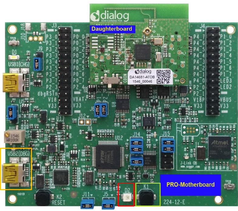
Fig. 17 The ProDev Kit (Motherboard and Daughterboard)

Fig. 18 General Purpose LED and BUTTON Schematics
| DA1468x Pin Name | Signal Name | Multiplexed with Functions |
|---|---|---|
| P1_5 | RTS | D2 LED, through J5 |
| P1_6 | CTS | K1 push button, through jumper J8 |
- Import and then make a copy of the freertos_retarget sample code found in the SDK of the DA1468x family of devices.
Note
It is essential to import the folder named scripts to perform various operations (including building, debugging, and downloading)
- In the target application, add/modify all the required code blocks as illustrated in the Code Overview section.
- Build the project either in Debug_QSPI or Release_QSPI mode and burn the generated image to the chip.
- Press the K2 button on Pro DevKit to start the chip executing its firmware.
- Select a serial console and open it. In this tutorial we have selected Tera Term which is a free and easy-to-use serial terminal. Follow the steps in the following figures to successfully establish a connection via the USB port. If you connect the device it is automatically displayed as an option (2).
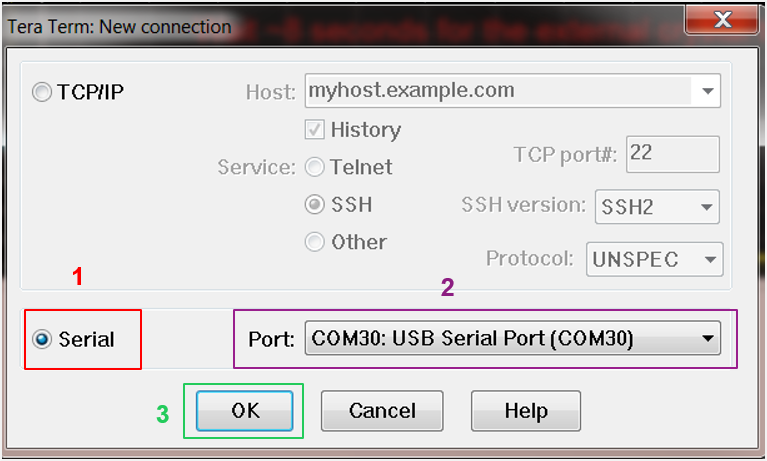
Fig. 19 Select the Serial Port to which the Development Kit is Connected
In the displayed window, select the UART parameters:
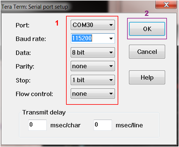
Fig. 20 Configure the Serial Port with the Correct Settings
After successfully setting the serial port you should see the special character ‘#’ displayed on the console.
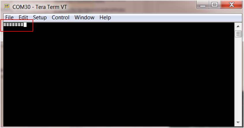
Fig. 21 The Special Character ‘#’ is Displayed on the Screen
- Press and release the K1 button on Pro DevKit three times. LED D2 on Pro DevKit should be turned on. For as long as LED D2 is active, the device is not allowed to enter sleep. Press and release the K1 button on Pro DevKit three times again. LED D2 should be turned off and the device should enter sleep.
Note
The number of events required for the led to toggle is configured through hw_wkup_set_counter_threshold API in init_wkup
routine.
4.2. Verifying with SmartSnippets Toolbox
- With the system up and running, open the SmartSnippets Toolbox and execute the following steps:
- (Optional) Select New to create a new project (1). In the New Project window, enter a name for the project (2). This step is optional if a project has already been created.
- Choose an available project (4).
- Choose a communication interface (3) and a port (5).
- Select the family of devices to use (6).
- Open the selected project (7).
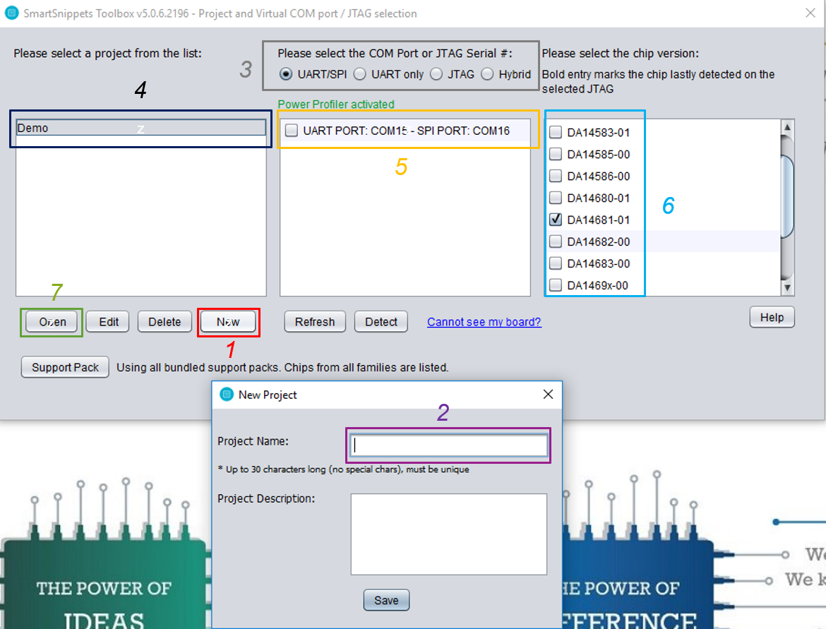
Fig. 22 Opening a Project in the SmartSnippets Toolbox
- Start power profile monitoring:
- Switch to the Power Profiler window (1).
- Initialize Power Profiler (2).
- Start Power Profiler (3).
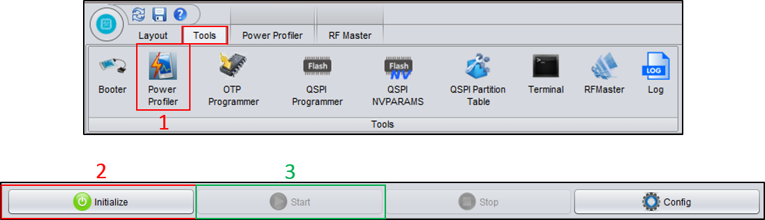
Fig. 23 Initializing Power Profiler
The following video shows how to use the Power Profiler.
Presentation of the SmartSnippets Toolbox
- Press the K2 button on Pro Dev Kit to reset the device. It should enter sleep approximately 8 seconds after a power-up event.
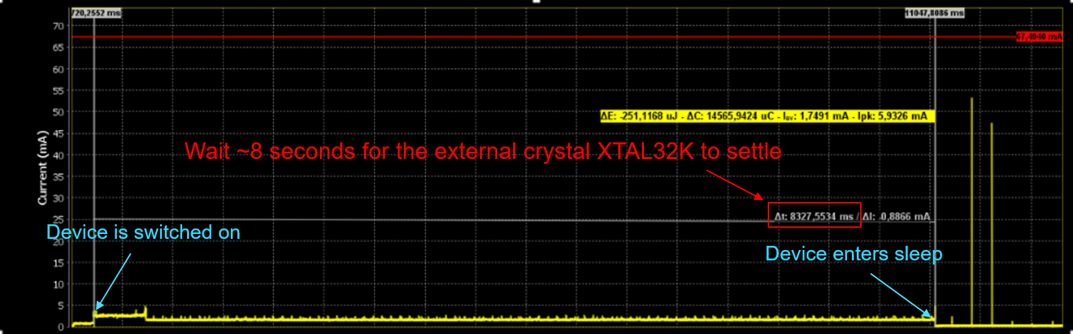
Fig. 24 Verifying the Correct Functionality of the Device before and after Entering Sleep
- After the passage of 8 seconds the device should wake up every 200ms (LED D2 is turned off).
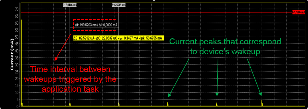
Fig. 25 Verifying the Correct Functionality of the Device between Wake-Ups
Press and release the K1 button on Pro DevKit three times. Verify the increased power consumption while the device is in active mode (LED D2 on).
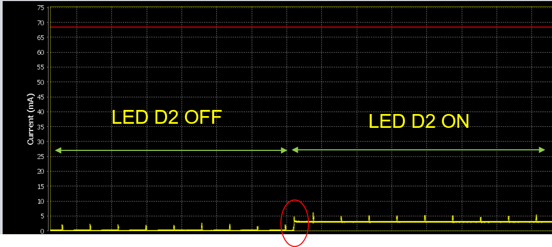
Fig. 26 Verifying the Power Consumption while in Active and Sleep Mode