7. SPI Flash
The following section details how to use the DA1453x Serial Peripheral Interface (SPI) to read/write a serial flash memory. Both the PRO and USB development kits contain a serial flash memory and we will use this to demonstate how to use the SPI flash functionality provided with SDK6.
Note
You must have created a modified version of the empty_peripheral_template example project, as described in the Initial Project chapter, before proceeding!
7.1. SPI Flash Memory Layout
Before using the SPI flash it is important to remember that, depending upon the operating mode, the SDK will use some of the flash. These areas should not be written to or erased by the user application. The SPI flash used on the DA14531 DEVKT-P and USB DEVKT is the Macronix MX25R2035 and on DA1453x DEVKT-P and USB DEVKT is the Renesas AT25DF021A-MAHN-T . These two are a 2Mb (256KByte) device.
- The areas used by the SDK6 are detailed in the following table:
Table 1 Flash Memory Layout Flash Address
Size
Description
0x0000 0000
Up to 48kB
If the application code is stored in flash then it is located here.
0x0000 BD80
Up to 74kB
Available for user data storage.
0x0001 E000
Up to 8kB
If the bonding table is located in flash then it is stored here. The size of the table is defined in app_bond_db.h.
0x0003 FFFF
Up to 128kB
Available for user data storage.
7.2. Hardware Configuration:
To use the onboard DA14531 or DA1453x DEVKT-P you need to connect the following pins over J1 on the Mother board:

Figure 10 J1 layout pins structure
7.3. SDK6 and SPI Flash Driver
The following section provides step-by-step instructions showing how to update the modified empty_peripheral_template example project you created in the Initial Project chapter to interface with a SPI Flash using the driver provided with SDK6.
7.3.1. Adding the SPI Flash Driver
The SPI flash driver is implemented in two files (spi_531.c and spi_flash.c) and these have already been added to the empty_peripheral_template example project.
7.3.2. Initializing the SPI Flash Driver
The SPI flash used on the PRO and USB development kits is the Macronix MX25R2035. We need to tell the flash driver that this is the flash we are using and also define the SPI configuration that should be used when communicating with it. This configuration is contained within two data structures that need to be added to the user_periph_setup.c file (just after the UART configuration - uart_cfg):
/* Default SPI configuration */
static const spi_cfg_t spi_cfg = {
    .spi_ms = SPI_MS_MODE_MASTER,
    .spi_cp = SPI_CP_MODE_0,
    .spi_speed = SPI_SPEED_MODE_4MHz,
    .spi_wsz = SPI_MODE_8BIT,
    .spi_cs = SPI_CS_0,
    .cs_pad.port = SPI_EN_PORT,
    .cs_pad.pin = SPI_EN_PIN,
#if defined (__DA14531__)
    .spi_capture = SPI_MASTER_EDGE_CAPTURE,
#endif
};

/* SPI flash configuration - assumes use of a Macronix MXR2035F as this is
   present on the DA145xx PRO development kit */
static const spi_flash_cfg_t spi_flash_cfg = {
    .dev_index = MX25R2035F_DEV_INDEX,
    .jedec_id  = MX25V2035F_JEDEC_ID,
    .chip_size = MX25V2035F_CHIP_SIZE,
};
To use the above data structures the following header files must be included in user_periph_setup.c:
#include "spi.h"
#include "spi_flash.h"
Finally we can initialize the flash driver using the above configuration by adding the following to the periph_setup function (just before set_pad_functions):
// Initialize interface to SPI flash so we can use it from within the application
spi_flash_configure_env(&spi_flash_cfg);
spi_initialize(&spi_cfg);
7.3.3. Disabling HW Reset
On the DA14531 and DA1453x DEVKTs P0_0 is used as the SPI MOSI (data out) signal. This pin is also the hardware reset input to the DA1453x and so before it can be used as SPI MOSI the reset functionality must be disabled. This can be accomplished by adding the following code to the start of user_on_init contained within empty_peripheral_template.c
// Disable HW RST on P0_0 so it can be used as SPI MOSI.
GPIO_Disable_HW_Reset();
7.3.4. Erasing SPI flash
Now that the driver and GPIO pins have been initialized we can perform various actions such as erasing, writing and reading the flash memory. We will perform these actions from within the user_on_init function contained within user_empty_peripheral_template.c and so need to add the SPI flash driver header to this file as follows:
#include "spi_flash.h"
Now, within the user_on_init function, add the following code to erase the flash sector that starts at address 0x20000:
int8_t ret;
ret = spi_flash_block_erase(0x20000, SPI_FLASH_OP_SE);
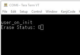
arch_printf("\n\rErase Status: %d", ret);
Note
If you want to erase more that one sector then it is strongly recommend that the watchdog is reloaded between each erase to ensure that it does not expire! This can be acheived by adding a call to wdg_reload(WATCHDOG_DEFAULT_PERIOD); after each sector erase operation.
When you build the project and run on your target you should see the following message being output via the serial debug port:
7.3.5. Writing to SPI Flash
Now that the flash sector has been erased we can write some data to it. To do this add the following code to the user_on_init function just after the code you added to erase the flash:
uint16_t bytes_written;
uint8_t data[8] = { 0, 1, 2, 3, 4, 5, 6, 7 };
ret = spi_flash_write_data(&data[0], 0x20000, sizeof(data), &bytes_written);
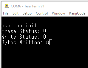
arch_printf("\n\rWrite Status: %d", ret);
arch_printf("\n\rBytes Written: %d", bytes_written);
When you rebuild the project and run it on your target you should see the following message being output via the serial debug port:
7.3.6. Reading from SPI Flash
Finally we can read back the data written in the following step by adding the following code to the user_on_init function just after the code you added to write to the flash:
uint16_t bytes_read;
uint8_t data_read[8] = { 0 };
ret = spi_flash_read_data(&data_read[0], 0x20000, sizeof(data_read), &bytes_read);
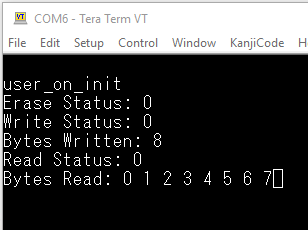
arch_printf("\n\rRead Status: %d", ret);
arch_printf("\n\rBytes Read:");
while (bytes_read) {
arch_printf(" %d", data_read[sizeof(data_read) - bytes_read]);
bytes_read--;
}
When you rebuild the project and run it on your target you should see the following message being output via the serial debug port:
7.4. Sleep Mode
After booting from flash the memory is left in its active state, allowing us to perform the read, write and erase operation described above. In order to reduce current consumption to a minimum the flash memory can be put into sleep mode by calling the spi_flash_power_down function. Once the flash has entered sleep mode the spi_flash_release_from_powerdown must be called to wake it before performing further read, write or erase operations.
7.5. Re-enabling HW Reset
Once all flash operations are complete the reset functionality of pin P0_0 can be restored, allowing switch SW1 on the development kit board to reset the DA14531. To do this add the following to the end of the user_on_init function:
// Re-enable HW reset input (must be disabled if/when further operations on
// external flash are performed) - must set as input first!
GPIO_ConfigurePin(SPI_DO_PORT, SPI_DO_PIN, INPUT_PULLDOWN, PID_GPIO, false);
GPIO_Enable_HW_Reset();
7.6. Putting it all Together
Once all of the above modifications have been made your user_on_init function should look like the one shown below:
void user_on_init(void)
{
    arch_printf("\n\r%s", __FUNCTION__);

    default_app_on_init();

    // Disable HW RST on P0_0 so it can be used as SPI MOSI.
    GPIO_Disable_HW_Reset();

    int8_t ret;
    ret = spi_flash_block_erase(0x20000, SPI_FLASH_OP_SE);
    arch_printf("\n\rErase Status: %d", ret);

    uint16_t bytes_written;
    uint8_t data[8] = { 0, 1, 2, 3, 4, 5, 6, 7 };

    ret = spi_flash_write_data(&data[0], 0x20000, sizeof(data), &bytes_written);
    arch_printf("\n\rWrite Status: %d", ret);
    arch_printf("\n\rBytes Written: %d", bytes_written);

    uint16_t bytes_read;
    uint8_t data_read[8] = { 0 };

    ret = spi_flash_read_data(&data_read[0], 0x20000, sizeof(data_read), &bytes_read);
    arch_printf("\n\rRead Status: %d", ret);
    arch_printf("\n\rBytes Read:");
    while (bytes_read) {
        arch_printf(" %d", data_read[sizeof(data_read) - bytes_read]);
        bytes_read--;
    }

    // Reduce power consumption by putting flash into sleep mode */
    spi_flash_power_down();

    // Re-enable HW reset input (must be disabled if/when further operation on
    // external flash are performed) - must set as input first!
    GPIO_ConfigurePin(SPI_DO_PORT, SPI_DO_PIN, INPUT_PULLDOWN, PID_GPIO, false);
    GPIO_Enable_HW_Reset();
}
Warning
Hardware reset is enabled immediately after changing P0_0 to input with pulldown. This works when built in development mode, but can cause repeated hardware resets when built for production. In production builds (CFG_DEVELOPMENT_DEBUG macro disabled), the pin may not reach a stable low level before the hardware reset logic is enabled. To ensures the pin reaches a stable low state before hardware reset is activated use:
Short delay: app_easy_timer(3, GPIO_Enable_HW_Reset);
instead of :
GPIO_Enable_HW_Reset();