Utilizing the Power Measurement Module (PMM2) and SmartSnippets™ Toolbox:
Users can initiate the data capturing process using the buttons under the Control tab located on the right side of the Power Profiler tool.
For PMM2 devices, charts are presented as docking frames, offering flexibility in management. Users can close them, resize them, or move them as needed.
Additionally, users can drag the docking frames outside the Toolbox tool to externalize them, enhancing visibility and usability.
For more detailed instructions, users can refer to the documentation provided at the specified link.
Using an External Power Analyzer:
This method is recommended for obtaining highly accurate power consumption measurements, particularly for ultra-low currents observed during the sleep phase of the device.
External power analyzers offer enhanced precision and sensitivity, ensuring reliable data capture even in scenarios involving minimal power consumption.
By employing an external power analyzer, users can achieve more accurate and reliable measurements, crucial for optimizing power efficiency and performance.
DA14592 DEVKIT-PRO and DA14594 DEVKIT-PRO
The DA14592 DEVKIT-PRO and DA14594 DEVKIT-PRO share the same motherboard. The only difference between these two development kits lies in their respective daughterboards. What applies to the DA14592 is equally applicable to the DA14594.
For clarity, this tutorial is using the DA14592 Dev Kit as an example.
This tutorial is based on the functionality of PMM2
In this user manual, we rely on the DA14592 DEVKT-P motherboard paired with its daughter board as our chosen hardware platform for testing. Our standard software framework, DA14592’s SDK10, remains consistent throughout this manual. This chapter will outline hardware configurations and necessary adjustments within the SDK. These modifications are crucial for seamless integration and optimal performance.
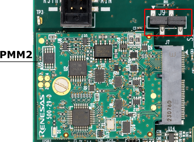
First difference comparing to older devkits on DA14592 DEVKT-P mother board is the power measurement module (pmm2) , which is an external add-on board connected via J7. It is expected that with PMM2 the measurements would be accurate down to 1uA. Header J9 is the PMM2 configuration header , In order to enable it , mount both jumpers 1-2 , 3-4 like the figure below:
Figure 1 As can be seen both jumpers needed to be closed like the figure
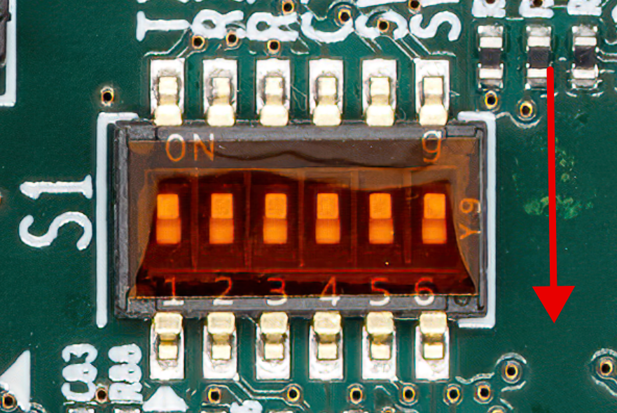
Dip Switches position while doing measurements
Ensure that the DIP switches on S1, which control the chip’s UART and SWD pins, are set to the “off” position. This configuration is crucial for preventing leakages of several uA. This is only necessary while doing the measurement , As you already know while downloading the firmware`s binary into flash, SWDIO and SWCLK should be set ON.
In order to start the measurement , first we need to perform a calibration to verifying and adjusting the accuracy of the instrument’s readings by comparing them to known standards or reference measurements.
Disconnect the daughterboard from the motherboard.
Connect the motherboard to the computer by cable
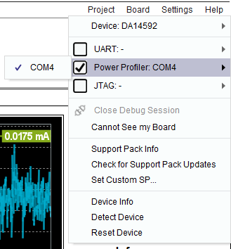
From top right corner select Board. From the opened menu , select DA14592 as your device
Enable the Powerprofiler from the menu.
Figure 3 Choose DA14592 DEVKT-P and enable Powerprofiler
By Selecting Offset Calibration the calibration session will start . At the end of calibration process , Avg CH1 (Low) Current (A) and Avg CH1 (High) Current (A) values should match with the values you are seeing in Configuration Dialog window (CH1CalibrationOffset(A) and CH2CalibrationOffset(A)).
Remember , whenever you close the toolbox every setting will change to default and you need to do the process again.
Note
It’s important not to set a trigger level (Control / Auto Trigger) as doing so will prevent offset calibration from functioning correctly. Although it will start and stop, both values will ultimately become 0.000000.