1. Example description
This example shows how to acquire data from an I2C accelerometer and send the measurements with BLE notifications using a DA14531 or DA14585/586 device. This example project also interfaces with an Evothings app which displays the orientation of the sensor, or you could use a BLE Scanner app to read out the measurements.
An I2C sensor is not necessary to run this example.
Defining NO_SENSOR in ADXL345.h disables reading of the sensor.
The application will send an incrementing number over BLE in this case.
The example can be downloaded from Here
2. HW and SW configuration
2.1. Hardware configuration
This example runs on the DA14531 or DA14585/DA14586 Bluetooth Smart SoC devices.
The DA145xx Pro Development Kit is needed for this example.
Follow the hardware configuration according to your daughterboard, DA14531 or DA14585/DA14586.
Hardware configuration for DA14531 devices
Connect the USB1 connector of the DA145xx Pro Development Kit to the host computer.
Connect the positive rail of your breadboard to pin V3 of the development board and the negative rail to any ground pin of the development board (the ones marked with a dash). Power up the sensor by connecting the 3.3V pin of the ADXL345 to your positive rail and the GND pin of the sensor to your negative rail.
Tie high the SDO and CS pins of the sensor to your positive rail. This enables the sensor to operate in I2C mode and adjusts the I2C sensor address to match the one defined in the project.
Connect the SCL pin of the ADXL345 to pin P23 of the development board.
Connect the SDA pin of the ADXL345 to pin P21 of the development board.
Hardware configuration for DA14585/DA14586 devices
Connect the USB1 connector of the DA145xx Pro Development Kit to the host computer.
Connect the positive rail of your breadboard to pin V3 of the development board and the negative rail to any ground pin of the development board (the ones marked with a dash). Power up the sensor by connecting the 3.3V pin of the ADXL345 to your positive rail and the GND pin of the sensor to your negative rail.
Tie high the SDO and CS pins of the sensor to your positive rail. This enables the sensor to operate in I2C mode and adjusts the I2C sensor address to match the one defined in the project.
Connect the SCL pin of the ADXL345 to pin P13 of the development board.
Connect the SDA pin of the ADXL345 to pin P11 of the development board.
2.2. Software configuration
This example requires:
SDK v6.0.14 or later
SEGGER’s J-Link tools should be downloaded and installed.
An application like LightBlue Explorer should be used to act as a BLE Scanner and view the received measurement values. It can be found on Google Play or on the App Store.
3. How to run the example
For initial setup of the example please refer to this section of the dialog support portal.
3.1. Compile and run
Start Keil µVision.
Optionally, change the parameters in ADXL345.h
Select the DA14531, DA14585 or DA14586 device in the box shown below

Compile and run the project.
3.2. Connecting to the device
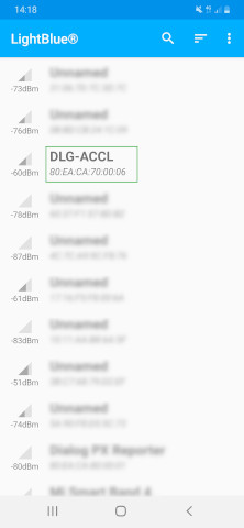
Open the BLE scanner app and look for DLG-ACCL
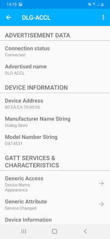
Connect to the device. Lightblue will list all the available services.
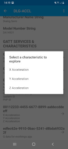
Select the characteristic you wish to explore, like the X acceleration data.
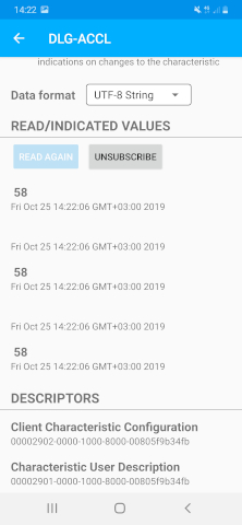
Subscribe to notifications and select the UTF-8 String data representation. You will be now ready to receive live the X acceleration (in milli g).
4. Known Limitations
There are no known limitations for this example. But you can check and refer to the following application note for known hardware limitations for DA1458x devices or known hardware limitations for DA14531 devices.
Dialog Software Forum link.
You can also refer to the DA14585/DA14586 Getting Started Guide with the PRO-Development Kit or the DA14531 Getting Started guide.
5. License
Copyright (c) 2021 Dialog Semiconductor. All rights reserved.
This software (“Software”) is owned by Dialog Semiconductor. By using this Software you agree that Dialog Semiconductor retains all intellectual property and proprietary rights in and to this Software and any use, reproduction, disclosure or distribution of the Software without express written permission or a license agreement from Dialog Semiconductor is strictly prohibited. This Software is solely for use on or in conjunction with Dialog Semiconductor products.
EXCEPT AS OTHERWISE PROVIDED IN A LICENSE AGREEMENT BETWEEN THE PARTIES OR AS REQUIRED BY LAW, THE SOFTWARE IS PROVIDED “AS IS”, WITHOUT WARRANTY OF ANY KIND, EXPRESS OR IMPLIED, INCLUDING BUT NOT LIMITED TO THE WARRANTIES OF MERCHANTABILITY, FITNESS FOR A PARTICULAR PURPOSE AND NON-INFRINGEMENT. EXCEPT AS OTHERWISE PROVIDED IN A LICENSE AGREEMENT BETWEEN THE PARTIES OR BY LAW, IN NO EVENT SHALL DIALOG SEMICONDUCTOR BE LIABLE FOR ANY DIRECT, SPECIAL, INDIRECT, INCIDENTAL, OR CONSEQUENTIAL DAMAGES, OR ANY DAMAGES WHATSOEVER RESULTING FROM LOSS OF USE, DATA OR PROFITS, WHETHER IN AN ACTION OF CONTRACT, NEGLIGENCE OR OTHER TORTIOUS ACTION, ARISING OUT OF OR IN CONNECTION WITH THE USE OR PERFORMANCE OF THE SOFTWARE.