1. Example description
This example shows how to:
Use a button to switch between advertising methods.
Sleep or wake up after pressing a button for 3 seconds.
Use timer callbacks to switch between advertising methods.
Use timer callbacks to go to sleep or wake up.
The expected result of the example can be verified by:
Connecting a serial terminal on the work station to the MB (Mother Board) using UART.
The status of the LED.
Note The example can be downloaded from Here.
2. HW and SW configuration
Hardware configuration
This example runs on the BLE Smart SoC (System on Chip) devices:
DA14585/DA14586 or DA14531 daughter board + DA145xxDEVKT-P PRO-Motherboard.
DA14585/DA14586 basic development kit.
The user manuals for the development kits can be found:
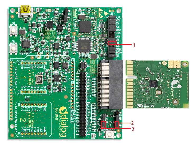
Hardware configuration DA14531 using DA145xxDEVKT-P PRO-Motherboard
UART TX: connect P21 on J2 to UTX pin 17 on J1 as shown in the image below (the blue line).
LED jumper on J8 is configured to P0_9 (red box 2).
Button jumper on J19 is configured from SW2 pin to P3_1 (red box 1)
To clarify the J19 configuration from up (see arrow on MB): pin, jumper, jumper, pin, pin.
Connect the DA145xxDEVKT-P PRO-Motherboard to the working station through USB1 connector.
The image below shows the Motherboard with jumper (wire) configuration for the DA14531.

Hardware configuration DA14585 using the DA145xxDEVKT-P PRO-Motherboard
UART TX jumper on P0_4, located on J1 (red box 1).
LED jumper is configured to P1_0, located on J8 (red box 3).
Button jumper is configured from SW3 pin to P1_1, located on J19 (red box 2).
Connect the DA145xxDEVKT-P PRO-Motherboard to the working station through USB1 connector.
The image below shows the Motherboard with jumper configuration for the DA14585
Hardware configuration DA14585 using the basic dev kit
UART TX/RX jumper on P0_4/P0_5, located on J4.
LED jumper is configured to P10, located on J9.
An active-low switch should be connected to P1_1, located on J4, as displayed in the following schematic.
Connect the basic dev kit to the working station through USB1 connector.

Software configuration This example requires:
Keil5.
SEGGER’s J-Link tools should be downloaded and installed.
Serial Terminal software. For example Tera Term or PuTTY.
3. How to run the example
3.1. Setup
Before launching the Keil project, make sure to link the SDK and project environment using the Python linker script dlg_make_keil_vx.xxx. More information Here.
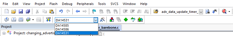
Start Keil using the
changing_advertising.uvprojxKeil project file.Expand the dialog shown in the red box in the image below.

Select your device: DA14531, DA14586 or DA14585.
Open a serial terminal on the work station using for example Tera Term/PuTTY with the following parameters:
- baud rate: 115200
- data: 8 bits
- stop: 1 bit
- parity: None
- flow  control: none
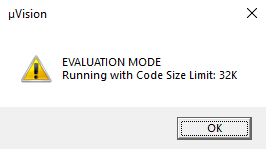
Compile (F7) and launch (ctrl + F5) the example.
If the warning shown below pops up press OK.
4. GPIO identification
Make sure to read the correct identification according to your mother board and daughter board.
4.1. DA14585/DA14586 GPIO identification with DA145xxDEVKT-P PRO-Motherboard
Identify LED:
The LED controlled in this example is
D5and the color isorange.
Identify button:
SW3is used as button in this example
4.2. DA14531 GPIO identification with DA145xxDEVKT-P PRO-Motherboard
Identify LED:
The LED controlled in this example is
D5and the color isorange.
Identify button:
SW2is used as button in this example
4.3. DA14585/DA14586 GPIO identification with Basic Dev Kit
Identify LED:
The LED controlled in this example is
USRand the color isgreen.
Identify button:
The button connected (by the user) to P1_1 on J4
5. Expected Results button example
The changing advertising example is now running.
Make sure that the ADV_EXAMPLE and the ADV_BUTTON_EXAMPLE are both defined defined in user_config.h.
Make sure CFG_PRINTF is defined if UART messages are desired.
The LED status is toggle when the advertising is started. The LED state will toggle between advertising changes and will remain off during permanent sleep periods.
The image below describes the behavior.

6. Expected Results timer example
The changing advertising example is now running.
Make sure ADV_EXAMPLE is defined in user_config.h (if only the ADV_EXAMPLE definition is enabled the demo will change the advertising state via timer).
Make sure that ADV_BUTTON_EXAMPLE is not defined.
Make sure CFG_PRINTF is defined if UART messages are desired.
The LED status is toggle when the advertising is started. The LED is set inactive when the system is going to sleep.
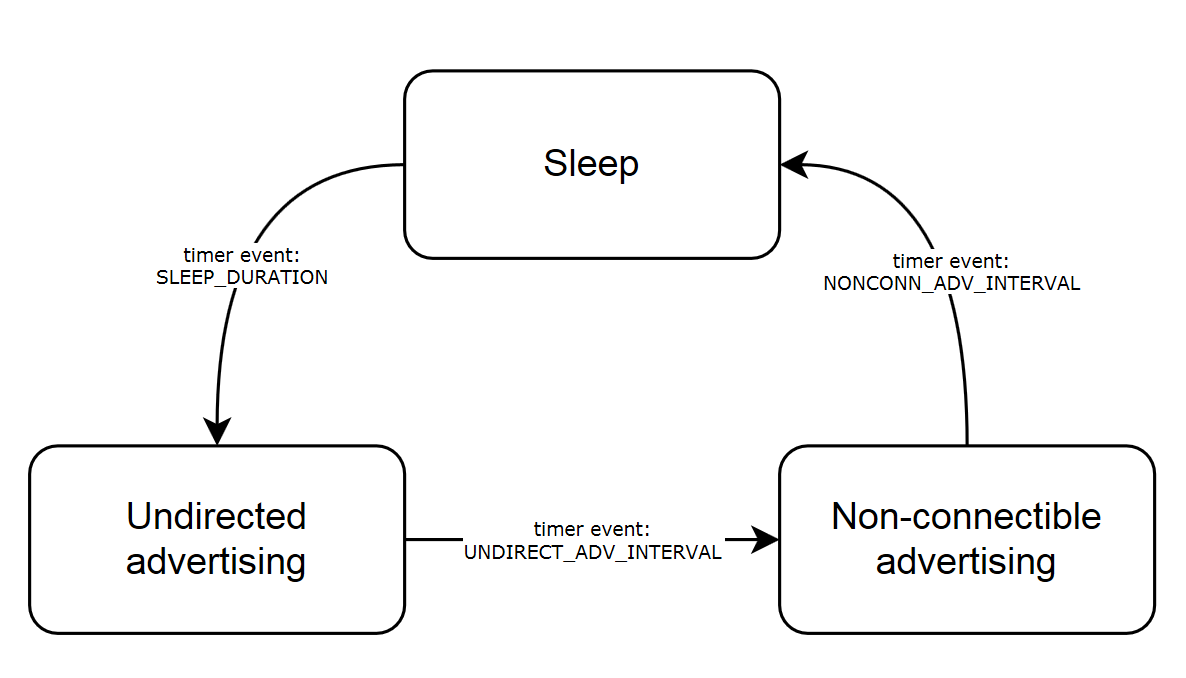
The image below describes the behavior.
7. Optional software configurations
The following parameters can be configured in user_barebone.h
Set UNDIRECT_ADV_INTERVAL to the desired value in milliseconds to configure the undirected advertising interval.
Set NONCONN_ADV_INTERVAL to the desired value in milliseconds to configure the non-connectible advertising interval.
Set UNDIRECT_ADV_DURATION to the desired value multiplied by 10 milliseconds to determine the duration of the undirected advertising in the timer based example.
Set NONCONN_ADV_DURATION to the desired value multiplied by 10 milliseconds to determine the duration of the non-connectible advertising in the timer based example.
Set SLEEP_DURATION to the desired value multiplied by 10 milliseconds to determine the sleep duration in the timer based example.
8. About this example
Starting point for this example is the BLE barebone project from SDK6. This provides the right framework for the advertising events used in this example.
Comparing to BLE barebone project from SDK6 some changes were made to user_barebone.c, these changes can be easily traced as they are marked with the ADV_EXAMPLE flag.
Minor changes were made to the user_peripheral_setup files to accommodate the button functionality and LED indication.
The user_callback_config.h has been slightly modified. Callback is added for non-connectible advertising.
The user_button.h and user_button.c were added. These files accommodate the button functionality used in this example.
9. Troubleshooting
Please check that the steps according to your daughter board (DA14531, DA14585 or DA14586) and mother board (basic dev kit or DA145xxDEVKT-P PRO-Motherboard) are followed correctly.
Try a different USB1 cable.
Try different jumper wire, if used.
If none of the steps described above help, please check the user manual according to your development kit.
10. License
Copyright (c) 2021 Dialog Semiconductor. All rights reserved.
This software (“Software”) is owned by Dialog Semiconductor. By using this Software you agree that Dialog Semiconductor retains all intellectual property and proprietary rights in and to this Software and any use, reproduction, disclosure or distribution of the Software without express written permission or a license agreement from Dialog Semiconductor is strictly prohibited. This Software is solely for use on or in conjunction with Dialog Semiconductor products.
EXCEPT AS OTHERWISE PROVIDED IN A LICENSE AGREEMENT BETWEEN THE PARTIES OR AS REQUIRED BY LAW, THE SOFTWARE IS PROVIDED “AS IS”, WITHOUT WARRANTY OF ANY KIND, EXPRESS OR IMPLIED, INCLUDING BUT NOT LIMITED TO THE WARRANTIES OF MERCHANTABILITY, FITNESS FOR A PARTICULAR PURPOSE AND NON-INFRINGEMENT. EXCEPT AS OTHERWISE PROVIDED IN A LICENSE AGREEMENT BETWEEN THE PARTIES OR BY LAW, IN NO EVENT SHALL DIALOG SEMICONDUCTOR BE LIABLE FOR ANY DIRECT, SPECIAL, INDIRECT, INCIDENTAL, OR CONSEQUENTIAL DAMAGES, OR ANY DAMAGES WHATSOEVER RESULTING FROM LOSS OF USE, DATA OR PROFITS, WHETHER IN AN ACTION OF CONTRACT, NEGLIGENCE OR OTHER TORTIOUS ACTION, ARISING OUT OF OR IN CONNECTION WITH THE USE OR PERFORMANCE OF THE SOFTWARE.