The wakeup_controller_demo uses both of existing buttons K1 and K2 on the DA1470x Development board for generating interrupts that can wake up the system.
The demo can be configured to wake up from:
Either the KEY_WAKEUP interrupt on K1 (WKUP_KEY_BLOCK_ENABLE set to 1).
Or the GPIO_WAKEUP interrupt on K2 (WKUP_GPIO_P1_BLOCK_ENABLE set to 1).
Or both KEY_WAKEUP and GPIO_WAKEUP on K1 and GPIO_WAKEUP interrupt on K2 (WKUP_KEY_BLOCK_ENABLE and WKUP_GPIO_P1_BLOCK_ENABLE both set to 1).
Note
The trigger polarity for the KEY_WAKEUP is controlled from the KEY_WKUP_TRIGGER_STATE definition. Set to 0 for a low pulse and 1 for high pulse as a trigger.
The trigger polarity for the GPIO_WAKEUP is controller from the GPIO_WKUP_TRIGGER_STATE definition. Set to 0 for a low pulse and 1 for high pulse as a trigger.
The wakeup controller circuitry for the GPIO_WAKEUP has the capability to be programmed to monitor edge or level sensitive triggers and latch them into a status register in order for the application be aware of the interrupt source.
If the trigger is edge or level sensitive can also be configured by the application via the GPIO_TRIGGER_SENSITIVITY definition. Set to 0 for a level sensitive and 1 for edge sensitive trigger.
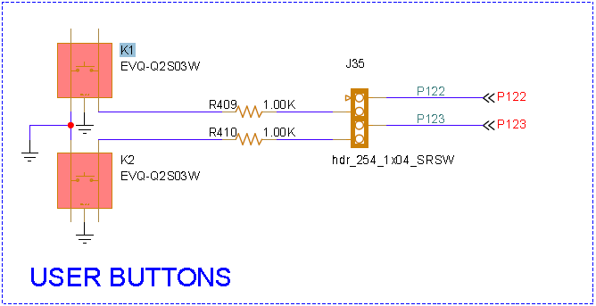
On the DA1470x Pro development kit the button K1 is mapped to the GPIO P1_22 and button K2 is mapped to the GPIO P1_23.
In order to detect an interrupt it is necessary to configure the GPIO as input pullup. As the board
schematic indicates both of the buttons are connecting the pins to the ground when the buttons are pressed in order to create a low pulse.
The configuration of the pins should be applied either directly in the prvSetupHardware() function or in the periph_init() function:
/* Configure the KEY1 push button on Pro DevKit */HW_GPIO_SET_PIN_FUNCTION(KEY1);HW_GPIO_PAD_LATCH_ENABLE(KEY1);/* Lock the mode of the target GPIO pin */HW_GPIO_PAD_LATCH_DISABLE(KEY1);/* Configure the KEY2 push button on Pro DevKit */HW_GPIO_SET_PIN_FUNCTION(KEY2);HW_GPIO_PAD_LATCH_ENABLE(KEY2);/* Lock the mode of the target GPIO pin */HW_GPIO_PAD_LATCH_DISABLE(KEY2);
Every interrupt source goes through the Power Domain Controller (PDC) block which is responsible for taking action right after waking up or before going to sleep.
In order to properly wake up from an interrupt source produced from the wakeup controller the corresponding entries should be programmed in the PDC in order for the controller to activate the corresponding master and power domain.
Note
The KEY_WAKEUP interrupt from the wakeup controller is multiplexed with the VBUS and the JTAG IRQ thus if only the WKUP_KEY_BLOCK_ENABLE is enabled no entries in the PDC are required from user code as long as the JTAG or the VBUS interrupts are enabled.
The next step is to initialize the Wake-Up Controller block and configure it to generate an interrupt on the configured edge. Then we need to register the callbacks which will handle the interrupts. There are two callback functions that each correspond to a different interrupt, the wkup_deb_interrupt_cb() corresponds to the the KEY_WAKEUP and the wkup_gpio_interrupt_cb() corresponds to the WAKEUP_GPIO interrupt.
The initialization of the wake up controller and registering the callbacks is done in the wkup_init() function which is invoked from the main() task of the demo.
/********************************* Custom wake up settings ************************************/wkup_configpin_wkup_conf={.debounce=10,.pin_wkup_state[HW_GPIO_PORT_1]=(KEY_WKUP_TRIGGER_ENABLED<<KEY1_PIN),.pin_gpio_state[HW_GPIO_PORT_1]=((KEY_WKUP_TRIGGER_ENABLED|GPIO_WKUP_TRIGGER_ENABLED)<<KEY1_PIN)|(GPIO_WKUP_TRIGGER_ENABLED<<KEY2_PIN),.pin_trigger[HW_GPIO_PORT_1]=(KEY_WKUP_TRIGGER_STATE<<KEY1_PIN)|(GPIO_WKUP_TRIGGER_STATE<<KEY2_PIN),.gpio_sense[HW_GPIO_PORT_1]=(GPIO_WKUP_TRIGGER_SENSITIVITY<<KEY1_PIN)|(GPIO_WKUP_TRIGGER_SENSITIVITY<<KEY2_PIN),};/********************************************************************************************/
/* Initialize the WKUP controller */staticvoidwkup_init(void){/* Initialize the WKUP controller */hw_wkup_init(&pin_wkup_conf);#if (WKUP_KEY_BLOCK_ENABLE)/* * Enable interrupts produced by the KEY block of the wakeup controller (debounce * circuitry) and register a callback function to hit following a KEY event. */hw_wkup_register_key_interrupt(wkup_deb_interrupt_cb,2);#endif#if (WKUP_GPIO_P1_BLOCK_ENABLE)/* * Enable interrupts produced by the GPIO block of the wakeup controller * and register a callback function to hit following a KEY event. */hw_wkup_register_gpio_p1_interrupt(wkup_gpio_interrupt_cb,1);#endif/* Enable interrupts of WKUP controller */hw_wkup_enable_key_irq();}
As already mentioned there are two callbacks, each handling a different interrupt, wkup_deb_interrupt_cb() triggered when the debounced interrupt source is triggered and wkup_gpio_interrupt_cb triggered when the gpio interrupt is triggered. In order to defer the handling of the interrupt inside the RTOS
we will generate a task notification from the interrupt handlers towards the extWakeUpTriggerTask.
The wkup_deb_interrupt_cb will clear the interrupt, will decide if the action is a button press or a release based on WKUP_TRIGGER_STATE definition and reconfigure the hardware for the next event. As soon as this is done it will notify the main task for the event.
voidwkup_deb_interrupt_cb(void){uint32_tevent=0;uint8_ttrigger=0;/* Clear the WKUP interrupt flag */hw_wkup_reset_key_interrupt();/* Mask the last bit from the enumeration, 0 stands for low 1 stands for high state */trigger=hw_wkup_get_trigger(KEY1_PORT,KEY1_PIN)&(1<<0);event=((trigger==KEY_WKUP_TRIGGER_STATE)?WKUP_KEY_PRESS_EVENT_NOTIF:WKUP_KEY_RELEASE_EVENT_NOTIF);pin_wkup_conf.pin_trigger[KEY1_PORT]=(!trigger<<KEY1_PIN)|(GPIO_WKUP_TRIGGER_STATE<<KEY2_PIN);hw_wkup_configure(&pin_wkup_conf);OS_TASK_NOTIFY_FROM_ISR(task_h,event,OS_NOTIFY_SET_BITS);}
The wkup_gpio_interrupt_cb will clear the interrupt, check the line state if it is high or low, clear the latched status and notify the main task for the event.
voidwkup_gpio_interrupt_cb(void){uint32_tstatus,event=0;/* Clear the WKUP interrupt flag */hw_wkup_reset_key_interrupt();/* Get the status and polarity of the selected port on last wakeup event. */status=hw_wkup_get_gpio_status(HW_GPIO_PORT_1);if(status&(1<<KEY1_PIN))event=(hw_wkup_get_trigger(KEY1_PORT,KEY1_PIN)&(1<<0))?WKUP_GPIO_P1_EVENT_NOTIF_HIGH:WKUP_GPIO_P1_EVENT_NOTIF_LOW;elseif(status&(1<<KEY2_PIN))event=(hw_wkup_get_trigger(KEY2_PORT,KEY2_PIN)&(1<<0))?WKUP_GPIO_P1_EVENT_NOTIF_HIGH:WKUP_GPIO_P1_EVENT_NOTIF_LOW;/* * This function MUST be called by any GPIO interrupt handler, * to clear the interrupt latch status. */hw_wkup_clear_gpio_status(HW_GPIO_PORT_1,status);OS_TASK_NOTIFY_FROM_ISR(task_h,event,OS_NOTIFY_SET_BITS);}
The notification send from the interrupt handlers will unblock the main task of the example extWakeUpTriggerTask and based on the task notification value it will print out the corresponding event.
staticOS_TASK_FUNCTION(extWakeUpTriggerTask,pvParameters){uint32_tulNotifiedValue;printf("Wake-up Controller Demonstration Sample Code.\n\r");#if dg_configUSE_WDOGint8_twakeup_task_wdog_id=-1;/* Register the Idle task first */wakeup_task_wdog_id=sys_watchdog_register(false);ASSERT_WARNING(wakeup_task_wdog_id!=-1);#endifwkup_init();for(;;){/* Notify watchdog on each loop */sys_watchdog_notify(wakeup_task_wdog_id);/* Suspend watchdog while blocking on ble_get_event() */sys_watchdog_suspend(wakeup_task_wdog_id);/* Wait for the external interruption notification */OS_TASK_NOTIFY_WAIT(0x0,OS_TASK_NOTIFY_ALL_BITS,&ulNotifiedValue,OS_TASK_NOTIFY_FOREVER);/* Trigger the watchdog notification */sys_watchdog_notify_and_resume(wakeup_task_wdog_id);/* Check the notification is the expected value */if(ulNotifiedValue&WKUP_KEY_PRESS_EVENT_NOTIF){printf("Key press occurred\n\r");}if(ulNotifiedValue&WKUP_KEY_RELEASE_EVENT_NOTIF){printf("Key release occurred\n\r");}if(ulNotifiedValue&WKUP_GPIO_P1_EVENT_NOTIF_LOW){printf("GPIO pulse low occurred\n\r");}if(ulNotifiedValue&WKUP_GPIO_P1_EVENT_NOTIF_HIGH){printf("GPIO pulse high occurred\n\r");}fflush(stdout);}}
Load the code on the the target development kit and start execution. Open a serial terminal of your choice with the following parameters:
115200 bps
8 bits
no flow control
1 stop bit
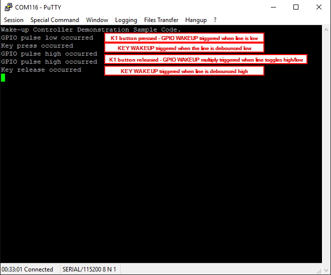
Depending on which functionality is enabled (WKUP_KEY_BLOCK_ENABLE or WKUP_GPIO_P1_BLOCK_ENABLE) and which button is pressed you should see the corresponding message printed on the terminal.
Pressing K1 button will trigger the KEY_WAKEUP interrupt, when the status of the line matches the KEY_WKUP_TRIGGER_STATE definition setting and GPIO_WAKEUP interrupt when the status of the line matches the GPIO_WKUP_TRIGGER_STATE definition setting.
Pressing K2 button will trigger only the GPIO_WAKEUP interrupt if the status of the line matches the GPIO_WKUP_TRIGGER_STATE definition setting.