4. Running The Demonstration Example
This section describes the steps required to prepare the Pro DevKit and other tools to successfully run the example code. A serial terminal, a breadboard, a few jumper wires are required for testing and verifying the code. If you are not familiar with the recommended process on how to clone a project or configure a serial terminal, read the Starting a Project tutorial.
4.1. Verifying with a Serial Terminal
Establish a connection between the target device and your PC through the USB1 port of the motherboard. This port is used both for powering and communicating to the DA1459x SoC. For this tutorial a Pro DevKit is used.
Import and then make a copy of the freertos_retarget sample code found in the SDK of the DA1459x family of devices.
Note
It is essential to import the folder named python_scripts to perform various operations (including building, debugging, and downloading).
In the newly created project and under the project’s
/configfolder you should create the following two files:platform_devices.c,platform_devices.h.
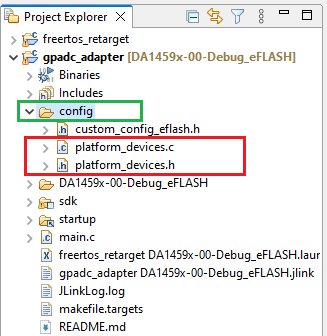
Figure 6 Creating New Files
Place the project’s
/configfolder in the compiler’s include path. To do this, selectProject > Properties > C/C++ Build > Settings > Tool Settings > Cross ARM C Compiler > Includesand click on the Add… icon (1.6).
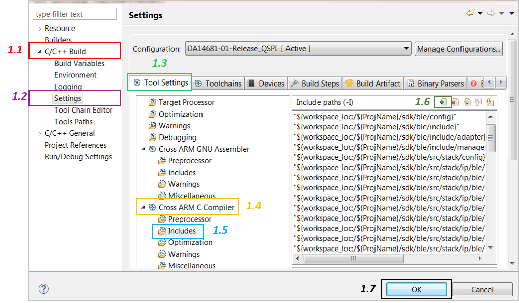
Figure 7 Add the New Folder to the Include Search Path
In the Add directory path window, click Workspace… and specify the path of the folder. It will be displayed in the Directory section. Click OK and then click OK in the previously opened window (1.7).
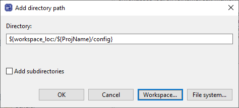
Figure 8 Input New Folder Name
Make sure the compiler does not generate errors instead of warnings. To do this, select
Project > Properties > C/C++ Build > Settings > Tool Settings > Warningsand deselect the corresponding tick box. Finally, click OK.
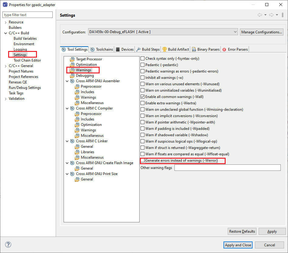
Figure 9 Configure Compiler’s Warnings
In the target application, add/modify all the required code blocks as illustrated in the Code Overview section.
Note
It is possible for the defined macros not to be taken into consideration instantly. Hence, resulting in errors during compile time. If this is the case, the easiest way to proceed with is to: right-click on the application folder, select Index > Rebuild and then Index > Freshen All Files.
Build the project either in Debug_eFlash or Release_eFlash mode and burn the generated image to the chip.
Connect the P100 (in J4) to Vdcdc (in J4) on the Pro DevKit.
Press the RESET button on Pro DevKit to start the chip executing its firmware.
Open a serial terminal (115200, 8-N-1). A debugging message is displayed on the console indicating the status of the current GPADC operation as well as the result of the analog-to-digital conversion.
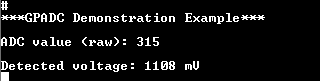
Figure 10 Debugging Messages for the Various Analog-to-Digital Operations
Change the input voltage level of the P1_0 pin by connect P100 (in J4) to VDDIO (in J4) or VBAT (in J4) and observe the new results on the serial console.