6. RF & Radio
This section describes the RF & Radio-related Frequently Asked Questions.
6.1. What is the Intermediate Frequency (IF) of the Radio?
The Intermediate Frequency (IF) of the radio is 1 MHz. See application note Bluetooth® Direct Test Mode that describes the required RF parameters for certification documents and how to setup the RF testing modes for the DA14531 Bluetooth® Low Energy SoC.
6.2. What does the Local Oscillator (LO) Frequency Does the Radio Usage?
The Local Oscillator (LO) frequency is: (2 x Carrier Frequency) + 1 MHz.
See application note Bluetooth® Direct Test Mode that describes the required RF parameters for certification documents and how to setup the RF testing modes for the DA14531 Bluetooth® Low Energy SoC.
6.3. What Communication Range can be Achieved with the DA14531?
The Bluetooth® SIG has published a range estimator on their website that can be used to calculate the effective, reliable range between Bluetooth® devices: https://www.bluetooth.com/bluetooth-technology/range/
6.4. Is a Pi Filter on the RFIOp Port Required?
Yes, to meet the product specification for ETSI, FCC and ARIB - a Pi Filter is needed to remove the out of band emission. Also, the extra Pi Filter for the RF circuit is needed to avoid Spurious Emissions Reduction. For more information on the antenna filters, see application note Designing Printed Antennas for Bluetooth® Smart.
The DXF files are available too.
6.5. Is 2 Mb/sec Data Throughput Supported?
No. DA14531 is fully compliant with Bluetooth® Low Energy 5.1 standard, where 2 Mb/s PHY support is optional. So, DA14531 supports up to 1 Mb/s.
6.6. Can I Change the Tx Power Level Using the Production Test Firmware?
The Production Test firmware that comes along with the SDK6.0.14 supports a configurable TX level.
The project is located under the projects\target_apps\prod_test SDK path.
The TX level can be changed by sending an appropriate command via UART (HCI_SET_TX_POWER_CMD_OPCODE).
In addition, the commands can be sent either with two-wire UART over P00/P01 or single-wire UART over P03 or P05.
The available commands and responses are shown in Figure 9 and Figure 10:
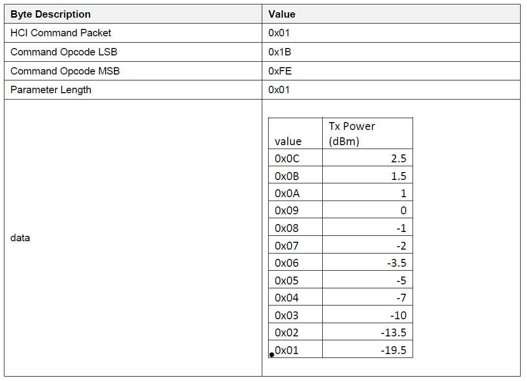
Figure 9 Tx Power Command

Figure 10 Tx Power Response
For this demonstration, single-wire UART is used over P05 to set the tx power at -18 dBm.
Prepare the DA145xx Pro Development kit for single-wire UART applied on P05 (see Figure 11). Install the three (3) Jumpers in Header J1 in the positions indicated by the blue rectangles in Figure 11. See also Figure 27 in Getting Started with the Pro Development Kit (HTML) document.
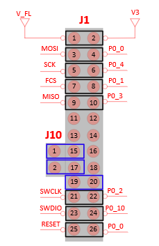
Figure 11 Configuration of DA145xx Pro DK for Single-Wire UART Applied on P05
Open the prod_test Keil project and navigate to
user_periph_setup.h. Configure the GPIOs for UART_TX / UART_RX for single-wire UART as shown in Figure 12.
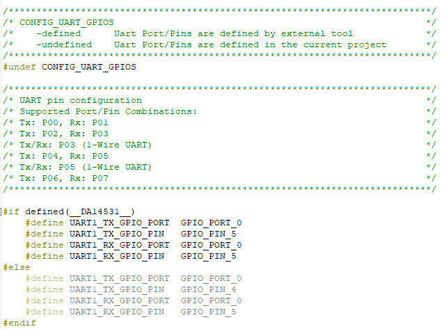
Figure 12 Configuration of user_periph_setup.h for Single-Wire UART Applied on P05
Build and run the prod_test.
To set the tx power at -18 dBm, enter the following characters 01 1B FE 01 01 over UART.
0x01 -> every command starts with a 0x01
0x1B 0xFE -> the op code of the sleep command 0xFE1B
0x01 -> parameter length
0x01 -> set the tx power at -18 dBm
6.7. Is Any Calibration of the RF Parameters Required in Production?
No, this is not required. Dialog Bluetooth® Low Energy devices are calibrated when the IC is manufactured. The accuracy of the 32MHz clock is essential for the quality of the RF. So, based on the application and the selected 32MHz xtal this might need trimming at application level. The Dialog Production Line Tool (PLT) supports XTAL trimming for 16 devices in parallel.