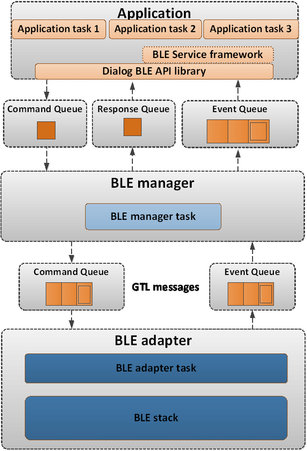
Using a top-down approach, the layers that build-up the BLE Framework functionality can be identified as the following:
The BLE service framework provides BLE services that the application can use “out-of-the-box”, using simple initialization functions and callbacks for the various BLE service events (like the change of an alert level attribute). The functionality of the BLE service framework is built on top of the Renesas BLE API library. The BLE service API header files can be found under <SDK_ROOT_PATH>/sdk/interfaces/ble/services/include. The BLE service callbacks are executed by the application task that uses the BLE service framework.
The Renesas BLE API is a set of functions that can be used to initiate BLE operations or respond to BLE events. The API header files can be found under the path <SDK_ROOT_PATH>/sdk/interfaces/ble/api/include. The API functions can be used to send messages (commands or replies to events) to the BLE manager, either by directly calling the BLE manager command handler or by using queues between the application task and the BLE manager task. The BLE API is called in the context of the application.
The BLE manager provides the interface to the BLE functionality of the chip. Only one application task must use the BLE functionality of the Renesas BLE API to interface with the BLE manager. Any other task need to send something to the BLE API, must defer it through the one task sending/receiving the BLE events. The BLE manager itself is a task (RTOS task) that stands between the application and the BLE adapter. The BLE adapter is the interface with the BLE controller running in the CMAC M0+ where the BLE stack is implemented. The BLE manager uses a Generic Transport Layer (GTL) interface to communicate with the BLE adapter through a command and event queue. The BLE adapter itself is a separate (RTOS task).
The BLE adapter is the system task that provides the interface to the BLE Stack. It runs the BLE Stack internal scheduler, receives the commands or the replies to events from the BLE manager, and passes BLE events to the BLE manager. BLE core functionality is implemented by the BLE adapter task.
The BLE Stack is the software stack that implements both the BLE Host and the Low Energy (LE) controller (Link Layer). The BLE Host includes the Logical Link Control and Adaptation Protocol (L2CAP), the Security Manager Protocol (SMP), the Attribute Protocol (ATT), the Generic Attribute Profile (GATT) and the Generic Access Profile (GAP). The BLE Stack API header files, for the DA1469x, can be found under <SDK_ROOT_PATH>/sdk/interfaces/ble/stack/<device_family>/include. The BLE Stack software is run under the BLE adapter’s task context
Important
Secure Store Functionality (RED Compliance)
To support RED compliance, a secure store feature has been added to SDK10.0.16. This enhancement enables the BLE Manager to securely store bonding data in encrypted form within QSPI flash memory.
Additionally, it provides a mechanism for user applications to securely store and retrieve encrypted sensitive data, ensuring protection against unauthorized access to external flash contents.
One of the main goals of the DA1469x SDK is to simplify the development of BLE applications and achieve a fast time to market. The DA1469x SDK separates the application logic from the BLE Stack implementation and provides a clean and powerful API to interact with the BLE capabilities of the device. The BLE API provides an easy way to configure the BLE device, start air operations and set up the attribute database of a GATT server. The BLE service API provides access to predefined Bluetooth SIG profiles with the definition of only a few callback functions.
The Proximity Reporter (pxp_reporter) application is the most typical of the BLE applications that are included in the DA1469x SDK. It is a complete and solid example of a BLE application developed on top of the DA1469x SDK. It uses both the Renesas BLE API and the BLE service framework to implement the functionality of a BLE profile.
However, it may not be the simplest example or the best starting point to become familiar with the development of a BLE application from scratch. Instead, there are BLE projects specifically created to serve as starting points for specific BLE applications such as beacons (ble_adv_demo) or specific roles such as a generic peripheral (ble_peripheral) or central (ble_central) device.
The goal of this section is to introduce the various options and examples that exist in the DA1469x SDK which can be used as building blocks for many applications. After a short introduction on where the API header files can be found, each section describes the functionality they implement along with guidance on how they differ from each other. This information is essential when developing a BLE application from scratch.
5.1.1.1. Updating BLE Application for User Data Secure Store Functionality
This section describes how to update a BLE application (e.g., pxp_reporter) to support User Data Secure Store functionality, which encrypts and stores secure data in flash memory using the AES-CTR algorithm
The pxp_reporter example can be updated to demonstrate secure storage of user data. Specifically, it encrypts battery level measurements using the AES-CTR algorithm, stores them in the LOG partition of the QSPI flash, and later decrypts the data to validate the storage process. This feature showcases how to securely store and retrieve sensitive information in compliance with RED.
How It Works:
Upon connection from a central device, the application periodically measures the battery level (default: every 60 ms).
Each measurement is:
Encrypted using AES-CTR
Stored in the LOG partition
During decryption, the data is read back, decrypted using the correct counter, and printed for verification.
AES-CTR requires a unique counter for each encryption. The application uses the relative address in the LOG partition as the counter to ensure cryptographic security.
Encryption and decryption operations use the Device Unique Symmetric Key (DUSK), stored in the last slot of the User Data Encryption Keys Payload section in OTP. If not already generated, use generate_dusk command.
Enabling the Feature
This feature is disabled by default, To enable secure user data storage in your BLE application:
Set the device GAP roles (central, peripheral, observer, broadcaster).
ble_gap_mtu_size_get()
Get the MTU size currently set.
ble_gap_mtu_size_set()
Set the MTU size to be used in MTU exchange transactions.
ble_gap_channel_map_get()
Get the currently set channel map of the device (the device has to be configured as central).
ble_gap_channel_map_set()
Set the channel map of the device (device has to be configured as central).
ble_gap_address_get()
Get the currently used BD address of the device.
ble_gap_address_set()
Set the BD address of the device.
ble_gap_device_name_get()
Get the device name used in the respective attribute of GAP service.
ble_gap_device_name_set()
Set the device name used in the respective attribute of GAP service.
ble_gap_appearance_get()
Get the appearance used in the respective attribute of GAP service.
ble_gap_appearance_set()
Set the appearance used in the respective attribute of GAP service.
ble_gap_per_pref_conn_params_get()
Get the peripheral preferred connection parameters used in the respective attribute of GAP service.
ble_gap_per_pref_conn_params_set()
Set the peripheral preferred connection parameters used in the respective attribute of GAP service.
ble_gap_get_io_cap()
Get the I/O capabilities of the device.
ble_gap_set_io_cap()
Set the I/O capabilities of the device (combined with the peer’s I/O capabilities, this will determine which pairing algorithm will be used).
ble_gap_data_length_set()
Set the data length to be used for transmission on new connections.
Advertising
ble_gap_adv_start()
Start advertising.
ble_gap_adv_stop()
Stop advertising.
ble_gap_adv_data_set()
Set the Advertising Data and Scan Response Data used.
ble_gap_adv_ad_struct_set()
Set Advertising Data and Scan Response Data using ::gap_adv_ad_struct_ttype.
ble_gap_adv_data_get()
Get currently used Advertising Data and Scan Response Data.
ble_gap_adv_intv_get()
Get the currently set advertising interval.
ble_gap_adv_intv_set()
Set the advertising interval (has to be done prior to ble_gap_adv_start()).
ble_gap_adv_chnl_map_get()
Get the advertising channel map currently set.
ble_gap_adv_chnl_map_set()
Set the advertising channel map (has to be done prior to ble_gap_adv_start()).
ble_gap_adv_mode_get()
Get the discoverability mode used for advertising.
ble_gap_adv_mode_set()
Set the discoverability mode used for advertising (has to be done prior to ble_gap_adv_start()).
ble_gap_adv_set_permutation()
Set the order of the primary advertising channels (Bluetooth Core v5.1 or later)
ble_gap_adv_filt_policy_get()
Get the filtering policy used for advertising.
ble_gap_adv_filt_policy_set()
Set the filtering policy used for advertising.
ble_gap_adv_direct_address_get()
Get the peer address used for directed advertising.
ble_gap_adv_direct_address_set()
Set the peer address used for directed advertising (has to be done prior to ble_gap_adv_start()).
Scanning
ble_gap_scan_start()
Start scanning for devices.
ble_gap_scan_stop()
Stop scanning for devices.
Connection management
ble_gap_scan_params_get()
Get the scan parameters used for future connections.
ble_gap_scan_params_set()
Set the scan parameters used for future connections.
ble_gap_connect()
Initiate a direct connection to a device.
ble_gap_connect_ce()
Initiate a direct connection with an application-defined minimum and maximum connection event length
ble_gap_connect_cancel()
Cancel an initiated connection procedure.
ble_gap_disconnect()
Initiate a disconnection procedure on an established link.
ble_gap_peer_version_get()
Get peer’s version on an established connection.
ble_gap_peer_features_get()
Get peer’s features on an established connection.
ble_gap_conn_rssi_get()
Get the RSSI of a connection.
ble_gap_conn_param_update()
Initiate a connection parameter update or update request procedure (depending on the role set and peer’s supported features).
ble_gap_conn_param_update_reply()
Reply to a connection parameter update request.
ble_gap_data_length_set()
Set the data length used for transmission on a specified connection.
ble_gap_phy_get()
Get the transmitter and receiver PHY (default preferred or for a specified connection).
ble_gap_phy_set()
Set PHY used for RX and TX (default or for a given connection).
Security
ble_gap_pair()
Start pairing.
ble_gap_pair_reply()
Respond to a pairing request.
ble_gap_passkey_reply()
Respond to a passkey request.
ble_gap_numeric_reply()
Respond to a numeric comparison request (LE Secure Connections only).
ble_gap_get_sec_level()
Get link security level.
ble_gap_set_sec_level()
Set link security level.
ble_gap_unpair()
Unpair device (will also remove the related bond data from BLE storage).
ble_gap_address_resolve()
Resolve a BD address using the set of IRKs stored in BLE storage.
Power Control
ble_gap_local_tx_power_get()
Get the current and maximum transmit power levels of the local device, on the ACL connection, for the indicated PHY.
ble_gap_remote_tx_power_get()
Get the TX power level used by the remote device, on the ACL connection, for the indicated PHY.
ble_gap_path_loss_report_params_set()
Set the path loss threshold reporting parameters.
ble_gap_path_loss_report_en()
Enable or disable path loss reporting.
ble_gap_tx_power_report_en()
Enable or disable reporting of TX power level in the local and remote device for the ACL connection.
ble_gap_rf_path_compensation_set()
Indicate the RF path gain or loss between the RF transceiver and the antenna contributed by intermediate components.
Helper functions
ble_gap_get_connected()
Get list of connected devices.
ble_gap_get_bonded()
Get list of bonded devices.
ble_gap_get_devices()
Return list of known devices based on filter.
ble_gap_get_device_by_addr()
Get the device object, given the device address.
ble_gap_get_device_by_conn_idx()
Get device object, given the connection index.
ble_gap_is_bonded()
Get bond state of device (by connection index).
ble_gap_is_addr_bonded()
Get bond state of device (by address).
Expert functions
ble_gap_skip_latency()
Temporarily ignore the connection latency.
GATT server API (ble_gatts.h): Set up the attribute database, set
attribute values, notify/indicate characteristic values, initiate MTU
exchanges, respond to write and read requests, etc.
Add a new GATT service to the ATT database. Subsequent calls to ble_gatts_add_include(), ble_gatts_add_characteristic() and ble_gatts_add_descriptor() will add attributes to the service added by this call.
ble_gatts_add_include()
Add an included service declaration to the service added by ble_gatts_add_service().
ble_gatts_add_characteristic()
Add a characteristic declaration to the service added by ble_gatts_add_service().
ble_gatts_add_descriptor()
Add a descriptor declaration to the service added by ble_gatts_add_service().
ble_gatts_register_service()
Add to the ATT database all attributes previously added to the service.
ble_gatts_enable_service()
Enable service in database.
ble_gatts_disable_service()
Disable service in database.
ble_gatts_get_characteristic_prop()
Read current characteristic properties and permissions.
ble_gatts_set_characteristic_prop()
Set characteristic properties and permissions.
ble_gatts_get_value()
Get attribute value.
ble_gatts_set_value()
Set attribute value.
ble_gatts_read_cfm()
Confirmation response to an attribute read request.
ble_gatts_write_cfm()
Confirmation response to an attribute write request.
ble_gatts_prepare_write_cfm()
Confirmation response to an attribute prepare write request.
ble_gatts_send_event()
Send a characteristic value notification or indication.
ble_gatts_service_changed_ind()
Send indication of the Service Changed Characteristic.
ble_gatts_get_num_attr()
Calculate the number of attributes required for a service.
GATT client API (ble_gattc.h): Used by a device configured as a GATT
client to discover the services, characteristics, etc. of a peer
device, read or write its attributes, initiate MTU exchanges, confirm
the reception of indications, etc.
Browse services on remote GATT server in a given range.
ble_gattc_discover_svc()
Discover services on a remote GATT server.
ble_gattc_discover_include()
Discover included services on a remote GATT server.
ble_gattc_discover_char()
Discover characteristics on a remote GATT server.
ble_gattc_discover_desc()
Discover descriptors on a remote GATT server.
ble_gattc_read()
Read a characteristic value or a characteristic descriptor from the remote GATT server, depending on the attribute handle.
ble_gattc_write()
Write a characteristic value or a characteristic descriptor to the remote GATT server, depending on the attribute handle.
ble_gattc_write_no_resp()
Write attribute to remote GATT server without response.
ble_gattc_write_prepare()
Prepare long/reliable write to remote GATT server.
ble_gattc_write_execute()
Execute long/reliable write to remote GATT server.
ble_gattc_indication_cfm()
Send confirmation for received indication.
ble_gattc_get_mtu()
Get current TX MTU of peer.
ble_gattc_exchange_mtu()
Exchange MTU.
Note
Several GAP configuration functions must be called before the attribute database is created, because modifying the device’s configuration can clear the attribute database created up to that point. This is noted in the Doxygen headers of the configuration functions that can have this effect.
Note: This feature is present in specific SDK releases only (please consult the SDK release notes document).
The LE Advertising Extensions feature was introduced by Bluetooth Specification Version 5.0 and allows larger amount of data
to be broadcasted in connectionless scenarios while also reducing the risk of advertising channel congestion. The basic advertising
packet size is increased to 255 bytes and packets can be chained to allow more advertising data to be transmitted (up to 1650 bytes).
Apart from the three advertising channels (37, 38, 39) and the LE 1M PHY that was allowed by Bluetooth 4.0 Legacy Advertising,
Advertising Extensions allow the transmission of advertising PDUs on the 37 data channels using LE 1M, LE 2M and Coded PHY, reducing the likelihood
of coexistence issues.
Note that, despite the addition of extended advertising PDUs and new procedures to support the new features,
compatibility with the legacy advertising PDUs and procedures is also maintained, making it possible for example
to connect to a device performing legacy advertising using the extended connection procedure, or to discover
devices performing legacy advertising using the extended scanning procedure and even perform legacy advertising
using the extended advertising procedure.
Advertising extensions define two sets of advertising channels: primary and secondary.
The primary advertising channels are the original 3 of the 40 advertising channels defined in Bluetooth 4 whereas
the secondary advertising channels use the 37 fixed channels previously reserved for data packets, exchanged during
an established connenction.
Table 54 describes the Advertising channel PDUs, along with their properties.
Table 54 Advertising channel PDUs, along with their properties.
PDU Name
Physical Channel
LE 1M
LE 2M
LE Coded *
ADV_IND
Primary
Yes
No
No
ADV_DIRECT_IND
Primary
Yes
No
No
ADV_NONCONN_IND
Primary
Yes
No
No
SCAN_REQ
Primary
Yes
No
No
AUX_SCAN_REQ
Secondary
Yes
Yes
Yes
SCAN_RSP
Primary
Yes
No
No
CONNECT_IND
Primary
Yes
No
No
AUX_CONNECT_REQ
Secondary
Yes
Yes
Yes
ADV_SCAN_IND
Primary
Yes
No
No
ADV_EXT_IND
Primary
Yes
No
Yes
AUX_ADV_IND
Secondary
Yes
Yes
Yes
AUX_SCAN_RSP
Secondary
Yes
Yes
Yes
AUX_SYNC_IND
Periodic
Yes
Yes
Yes
AUX_CHAIN_IND
Secondary and Periodic
Yes
Yes
Yes
AUX_CONNECT_RSP
Secondary
Yes
Yes
Yes
Note: The LE Coded PHY is not supported by the current SDK release.
Advertising Extensions define two main categories of advertisements:
Legacy Advertisements, used by the previous versions of Bluetooth Low Energy versions 4.0, 4.1, 4.2 that also exist in 5.0. They inlcude the following PDU types:
ADV_IND
ADV_DIRECT_IND
ADV_NONCONN_IND
ADV_SCAN_IND
Extended Advertisements, introduced in Bluetooth Low Energy version 5.0. They inlcude the following PDU types:
ADV_EXT_IND
AUX_ADV_IND
AUX_CHAIN_IND
The type of advertisement taking place is chosen by the parameters provided to ble_gap_ext_adv_param_set()
(and more specifically using the GAP_EXT_ADV_PROP_LEGACY bit on the properties field of the gap_ext_adv_params_t input parameter).
LE Advertising extensions use the notion of AdvertisingSet to identify independent advertising procedures
that are interleaved by the controller, using different advertising parameters (Advertising type, Interval, PHY) and data.
This means that it is possible for the application to enable more than one advertising operations at the same time,
(for example a Connectable along with a Non-Connectable and Non-Scannable operation) which the controller will interleave.
The number of supported Advertising Sets can be fetched using the ble_gap_supp_adv_sets_num_get() API call.
Since it is possible for a device to enable multiple advertising operations at the same time, it should be possible
for the remote scanning device to identify the advertising set where its operation uses so that it can distinguish
the advertising events (for filtering or other reasons). The advertiser device specifies this
using the sid field of the gap_ext_adv_params_t input parameter provided to ble_gap_ext_adv_param_set() (which should normally match the handle input
parameter of the same function) , and this in turn is accessible by the remote scanning device using the SID subfield of the
ADI field on the respective PDUs.
Extended advertising may use multiple PHYs and spread the payload across many PDUs to allow for much larger payloads.
Extended advertising is split across primary advertising on the advertising channels (37, 38, 39) and secondary advertising
on the channels normally used for sending data during established connections (0 - 36). The channels and PHY used in the primary advertising
channel along with the PHY used in the secondary channel can be speficified using the primary_channel_map, primary_phy
and secondary_phy fields on the parameters provided to ble_gap_ext_adv_param_set().
Note: Devices performing extended
advertising can only be discovered by devices that support the LE Avertising Extensions feature. It is therefore recommended
that devices use two advertising sets to perform advertising: One to perform extended advertising, and a second one to perform
legacy advertising so that they can be discovered by older scanning devices.
LE Advertising Extensions introduced also the notion of “anonymous” advertising, which basically allows an advertiser to
perform extended Non-Connectable and Non-Scannable advertising whithout exposing its address in any of the advertising PDUs.
Table 55 describes the Advertising Event Types supported by Legacy PDUs, (GAP_EXT_ADV_PROP_LEGACY set in the advertising parameters) along with their properties.
Table 55 Advertising Event Types supported by Legacy PDUs
Advertising Event Type using Legacy PDUs
Used PDUs
Allowable Response PDUs
Connectable
Scannable
Directed
High Duty Cycle
Anonymous
Connectable and Scannable Undirected
ADV_IND
SCAN_REQ,
CONNECT_REQ
Yes
Yes
No
No
No
Connectable Directed (low duty cycle)
ADV_DIRECT_IND
CONNECT_REQ
Yes
No
Yes
No
No
Connectable Directed (high duty cycle)
ADV_DIRECT_IND
CONNECT_REQ
Yes
No
Yes
Yes
No
Scannable Undirected
ADV_SCAN_IND
SCAN_REQ
No
Yes
No
No
No
Non-Connectable and Non-Scannable undirected
ADV_NONCONN_IND
None
No
No
No
No
No
Table 56 describes the Advertising Event Types supported by Extended PDUs, (GAP_EXT_ADV_PROP_LEGACY not set in the advertising parameters) along with their properties.
Table 56 Advertising Event Types supported by Extended PDUs
Advertising Event Type using Extended PDUs
Used PDUs
Allowable Response PDUs
Connectable
Scannable
Directed
High Duty Cycle
Anonymous
Connectable Undirected
ADV_EXT_IND,
AUX_ADV_IND
AUX_CONNECT_REQ
Yes
No
No
No
No
Connectable Directed
ADV_EXT_IND,
AUX_ADV_IND
AUX_CONNECT_REQ
Yes
No
Yes
No
No
Non-Connectable and Non-Scannable Undirected
ADV_EXT_IND,
AUX_ADV_IND
None
No
No
No
No
Optional
Non-Connectable and Non-Scannable Directed
ADV_EXT_IND,
AUX_ADV_IND
None
No
No
Yes
No
No
Scannable Undirected
ADV_EXT_IND,
AUX_ADV_IND
AUX_SCAN_REQ
No
Yes
No
No
No
Scannable Directed
ADV_EXT_IND,
AUX_ADV_IND
AUX_SCAN_REQ
No
Yes
Yes
No
No
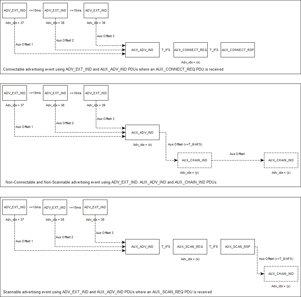
Figure 50 depicts examples of extended advertising events. Note that the presense and number
of AUX_CHAIN_IND PDUs depends on the length of advertising data (in case of Non-Connectable and Non-Scannable events) or
scan response data (in case of Scannable events) and the scheduling taking place in the controller.
AUX_CHAIN_IND PDUs are not present during Connectable events.
Figure 50 Examples of Extended Advertising Events
Table 57 describes the BLE functions related to the Extended Advertising operation.
Table 57 API Functions for Extended Advertising operation
Function
Description
ble_gap_supp_adv_sets_num_get()
Get the number of supported advertising sets.
ble_gap_max_adv_data_len_get()
Get the maximum supported data length that can be used as advertisement data or scan response data.
ble_gap_ext_adv_param_set()
Set the extended advertising parameters for a specific advertising set.
ble_gap_ext_adv_start()
Start extended advertising on a specific advertising set.
ble_gap_ext_adv_data_update()
Update the advertising and scan response data for a specific advertising set.
ble_gap_ext_adv_stop()
Stop extended advertising on a specific advertising set.
ble_gap_adv_set_remove()
Remove a specific advertising set.
Table 58 describes the BLE events related to the to the Extended Advertising operation
Table 58 Events related to Extended Advertising operation
Event
Description
BLE_EVT_GAP_SCAN_REQ_RECEIVED
Indicates that a scan request (SCAN_REQ or AUX_SCAN_REQ PDU) has been received by the advertiser.
BLE_EVT_GAP_EXT_ADV_TERMINATED
Indicates that extended advertising procedure has been completed.
Periodic advertising consists of advertisement PDUs (AUX_SYNC_IND) that are sent at a fixed interval.
This allows one or more scanners to synchronize with the advertiser so that the scanners and advertiser
would wake up at the same time, allowing the scanners to turn off their receiver when not needed.
The AUX_SYNC_IND PDUs can be combined with chained PDUs (AUX_CHAIN_IND)
allowing an even higher overall data throughput (up to 1650 bytes). Even though the periodic advertising
interval is fixed, the advertising data can change between those intervals.
To configure and enable periodic advertising (using ble_gap_periodic_adv_param_set(), ble_gap_periodic_adv_data_set()
and ble_gap_periodic_adv_enable()), one should first configure the specific advertising set for
Non-Connectable Non-Scannable extended advertising (using ble_gap_ext_adv_param_set()).
Note that even though enabling the periodic advertising (using ble_gap_periodic_adv_enable()) before the
extended advertising has been enabled (using ble_gap_ext_adv_start()) on the particular advertising set is possible,
the periodic advertisement will only start just after enabling the extended advertisement (using ble_gap_ext_adv_start()).
This means that to start periodic advertising, one should first start extended advertising.
After both the extended and periodic advertisements have been started, it is possible to stop the extended advertising
(using ble_gap_ext_adv_stop()) and let the periodic advertising go on alone. It is also possible to start the
extended advertisement again while the
periodic advertisement is enabled, if needed. Note that, althought the periodic advertising is autonomous and can remain enabled even
when the extended advertising is disabled, the only way for a scanner to get the timestamp, interval and PHY of a periodic advertising train
(AUX_SYNC_IND followed by zero or more AUX_CHAIN_IND PDUs) is by accessing the fields of the extended advertising PDUs (AUX_ADV_IND).
A common application scenario would be to enable both the extended and periodic advertising until one or more scanners get
synchronized with the periodic advertising train. The advertiser could then disable the extended advertising and keep only
the periodic advertising enabled to reserve power and bandwidth.
Periodic advertisements should be configured with a non-zero length of periodic advertising data.
These data are sent using AUX_SYNC_IND PDUs. If the data of the periodic advertisement do not fit
into a single PDU (or the controller decides to split them into more PDUs),
the AUX_SYNC_IND will be combined by AUX_CHAIN_IND PDUs.
A possible sequence of actions to enable periodic advertisement is shown below:
ble_gap_ext_adv_param_set()
ble_gap_periodic_adv_param_set()
ble_gap_periodic_adv_data_set()
ble_gap_periodic_adv_enable()
(Periodic advertising is kept disabled until ble_gap_ext_adv_start() gets called)
ble_gap_ext_adv_start()
(Both Extended and Periodic advertising should be enabled at this point)
It is also possible to configure and enable the periodic advertisement after enabling the extended advertisement:
ble_gap_ext_adv_param_set()
ble_gap_ext_adv_start()
(Extended advertising should be enabled at this point)
ble_gap_periodic_adv_param_set()
ble_gap_periodic_adv_data_set()
ble_gap_periodic_adv_enable()
(Both Extended and Periodic advertising should be enabled at this point)
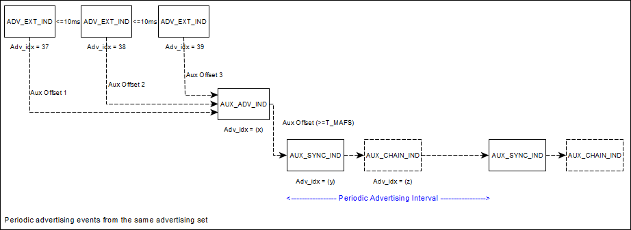
Figure 51 depicts an example of periodic advertising. Note that the presense and number
of AUX_CHAIN_IND PDUs depends on the length of periodic advertising data and the scheduling taking place in the controller.
The BLE stack will enter the scanning state when ble_gap_ext_scan_start() is executed. When scanning, the controller listens
on the primary advertising physical channel for the types of PDUs and PHYs that are provided as parameters.
On receiving a PDU with an auxiliary pointer (AuxPtr field) present (ADV_EXT_IND`, AUX_SCAN_RSP, AUX_CHAIN_IND) , the scanner also
listens for the auxiliary PDU it points to (provided that the relevant PHY is supported) and will then attempt to receive it.
During scanning, the controller listens on a primary advertising channel index for the duration of the scan window (window field
of gap_ext_scan_phy_params_t). The scan interval (interval field of gap_ext_scan_phy_params_t) , is defined as the interval between the start of two
consecutive scan windows.
Extended advertising reports with the advertising or scan response data will be sent when the controller receives the relevant PDU types
(ADV_IND, ADV_DIRECT_IND, ADV_NONCONN_IND, ADV_SCAN_IND, ADV_SCAN_RSP, AUX_ADV_IND, AUX_SCAN_RSP, AUX_CHAIN_IND).
Note that the extended advertising reports that will be forwarded to the application (using BLE_EVT_GAP_EXT_ADV_REPORT events)
depend on the selected discovery mode (GAP_SCAN_GEN_DISC_MODE, GAP_SCAN_LIM_DISC_MODE, GAP_SCAN_OBSERVER_MODE).
The scan operation can be stopped either from the application code (using the ble_gap_ext_scan_stop() function), or autonomously by the BLE
stack Host (if GAP_SCAN_GEN_DISC_MODE or GAP_SCAN_LIM_DISC_MODE discovery modes are used), or by the BLE
stack Controller (depending on the values of duration and period fields of the gap_ext_scan_params_t structure). In
any case a BLE_EVT_GAP_EXT_SCAN_COMPLETED event will be received by the application with the relevant status code.
Table 60 describes the BLE functions related to the Extended Scanning operation.
Table 60 API Functions for Extended Scanning operation
Function
Description
ble_gap_ext_scan_start()
Start extended scanning procedure.
ble_gap_ext_scan_stop()
Stop extended scanning procedure (initiated using ble_gap_ext_scan_start()).
Table 61 describes the BLE events related to the to the extended scanning operation
Table 61 Events related to extended scanning operation
Event
Description
BLE_EVT_GAP_EXT_ADV_REPORT
Indicates that the controller has received an extended advertisment during active or passive scan.
BLE_EVT_GAP_EXT_SCAN_COMPLETED
Indicates that extended scanning procedure has been completed.
5.1.7. Scanning and synchronizing to periodic advertisements
As described in the Periodic Advertising section, it is possible for an advertiser to broadcast periodic advertisements that
the scanners supporting the feature would be able to receive. To synchronize with a periodic advertiser, one should use the
ble_gap_periodic_adv_sync_create() function, providing as input parameters the SID (advertising set ID) and address of the remote advertiser.
When the synchronization is established (an event that will be signaled using BLE_EVT_GAP_PERIODIC_ADV_SYNC_ESTABLISHED) the scanner will
begin receiving periodic advertising packets (BLE_EVT_GAP_PERIODIC_ADV_REPORT events). Note that, even though the ble_gap_periodic_adv_sync_create()
function be called even when extended scanning is disabled (ble_gap_ext_scan_start() has not been called yet), synchronization
establishment can only occur when scanning is enabled. Once the synchronization has been established, the extended scanning operation
can be disabled without affecting the synchronization with the advertiser. Synchronization can be terminated later on using the
ble_gap_periodic_adv_sync_terminate() function. In case where the synchronization is lost unexpectedly the application will be notified using the BLE_EVT_GAP_PERIODIC_ADV_SYNC_LOST event.
The synchronization procedure normaly begins by initiating an extended scan procedure (using ble_gap_ext_scan_start()).
During the reception of extended advertiser
reports the scanner can discover any periodic advertisers in the same area by checking the periodic_adv_intv field of BLE_EVT_GAP_EXT_ADV_REPORT
events (which is non-zero when the respective advertiser has enabled periodic advertising). Extended advertiser reports also indicate
the address and SID used be the remote device, which should be provided as input parameters to ble_gap_periodic_adv_sync_create().
Table 62 describes the BLE functions related to the Periodic Scanning operation.
Table 62 API Functions related to periodic advertising synchronization operation
Function
Description
ble_gap_periodic_adv_list_size_get()
Get the total number of Periodic Advertiser list entries that can be stored in the Controller.
ble_gap_periodic_adv_sync_create()
Synchronize with a periodic advertising train from an advertiser and begin receiving periodic advertising packets.
ble_gap_periodic_adv_sync_cancel()
Cancel an ongoing synchronization procedure (initiated using ble_gap_periodic_adv_sync_create()) while it is pending.
ble_gap_periodic_adv_receive_options_set()
Change the receive options of an established sync procedure (initiated using ble_gap_periodic_adv_sync_create()), identified by the sync_handle parameter.
ble_gap_periodic_adv_sync_terminate()
Terminate an established sync procedure (initiated using ble_gap_periodic_adv_sync_create()), identified by the sync_handle parameter.
Table 63 describes the BLE events related to the to the periodic advertising synchronization operation
Table 63 Events related to periodic advertising synchronization operation
Event
Description
BLE_EVT_GAP_PERIODIC_ADV_SYNC_ESTABLISHED
Indicates that the controller has received the first periodic advertising packet from an advertiser (When status is BLE_STATUS_OK), or that synchronization failed.
BLE_EVT_GAP_PERIODIC_ADV_REPORT
Indicates that the controller has received a periodic advertisement
BLE_EVT_GAP_PERIODIC_ADV_SYNC_LOST
Indicates that the controller has not received a periodic advertisement from the remote advertiser within a timeout period
The BLE stack will enter the initiating state when ble_gap_ext_connect() is executed. When initiating, the controller listens
on the primary advertising physical channel on the PHYs that are provided as parameters.
During initiating, connection indications (CONNECT_IND PDU) are sent in response to a connectable advertisement in the primary advertising physical
channel (in case of ADV_IND and ADV_DIRECT_IND PDUs) while
connection requests (AUX_CONNECT_REQ PDU) are sent in response to a connectable advertisement in the secondary advertising physical
channel (in case of directed or undirected connectable AUX_ADV_IND PDUs). After sending the AUX_CONNECT_REQ PDU,
the controller waits for the advertiser to send an AUX_CONNECT_RSP PDU. Once an
AUX_CONNECT_RSP PDU is received, the controller exits the initiating state and transitions to the connection state.
The connection operation can be canceled (before a connection is been established) using the ble_gap_ext_connect_cancel() function.
It will be also stopped in case where a connection has been established. In any case
a BLE_EVT_GAP_EXT_CONNECTION_COMPLETED event will be received by the application with the relevant status code.
If the connection is established successfully, the application will also receive a BLE_EVT_GAP_CONNECTED event.
Table 64 describes the BLE functions related to the Extended Connection operation.
Table 64 API Functions for Extended Connection operation
Function
Description
ble_gap_ext_connect()
Connect to a device using the extended connection procedure.
ble_gap_ext_connect_cancel()
Cancel extended connection procedure (initiated using ble_gap_ext_connect()).
Table 65 describes the BLE events related to the to the Extended Connection operation
Table 65 Events related to Extended Connection operation
Event
Description
BLE_EVT_GAP_EXT_CONNECTION_COMPLETED
Indicates that extended connection procedure has been completed.
The BLE service API header files are in
<SDK_ROOT_PATH>/sdk/interfaces/ble/services/include.
The services-specific API, callback function prototypes and definitions
are included in each service’s header file. The services implemented are
the following:
All services have an initialization function defined. This function is called with arguments that vary for different services.
The most common argument is a pointer to one or more callback functions that should be called upon a service-specific event. For example, the prototype for the initialization function of the Immediate Alert Service (ias.h) is the following:
Code 40 Initialization code for Immediate Alert Service
Function ias_init() has only one argument. It is a pointer to the callback function that will be called when a peer device has modified the value of the Immediate Alert Level characteristic. This callback function is part of the user application code and should provide the application handling required for the change to the Immediate Alert Level.
The return value from all initialization functions is the created service’s handle which is used to reference the service in the application. To understand how the service interacts with the BLE Framework it is useful to know what this handle represents. The handle is a pointer to a generic structure (ble_service_t) that defines how the service should interact with the framework. Within each service there is an internal service definition (XXX_service_t) as shown in Figure 52. This contains the generic service structure plus a set of handles, one for each GATT characteristic that the service implements. This XXX_service_t structure is populated by XXX_init() for that service. The start_h and end_h handles will contain the start and end handles of the attributes for this service within the overall GATT table provided by the GATT server. So, when a GATT client requests a Service Discovery from the server these represent the start and end handles that the client would use to access service XXX.
The set of optional callbacks allow each service to specify if it wants to do some specific handling on a certain event received by the BLE Framework. If the service wants to be informed when another BLE device has connected to this device then it can define its own handle_connected_evt() function and plug it into the connected_evt callback. Each service declares its handle_connected_evt() function as static in xxx.c and by convention in the SDK they all share the same function names in each service.
As each service is initialized and thus added to the BLE services framework with ble_service_add(), its generic services structure is added to a structure of supported services as shown in Figure 53.
Now that the main internal services structure has been explained, it is easier to follow how the service initialization defines how the service operates.
Within the BLE service framework, the main event handler is ble_service_handle_event() which is shown below.
Code 41 Handle BLE events using BLE service framework
boolble_service_handle_event(constble_evt_hdr_t*evt){switch(evt->evt_code){caseBLE_EVT_GAP_CONNECTED:connected_evt((constble_evt_gap_connected_t*)evt);returnfalse;// make it "not handled" so app can handlecaseBLE_EVT_GAP_DISCONNECTED:disconnected_evt((constble_evt_gap_disconnected_t*)evt);returnfalse;// make it "not handled" so app can handlecaseBLE_EVT_GATTS_READ_REQ:returnread_req((constble_evt_gatts_read_req_t*)evt);caseBLE_EVT_GATTS_WRITE_REQ:returnwrite_req((constble_evt_gatts_write_req_t*)evt);caseBLE_EVT_GATTS_PREPARE_WRITE_REQ:returnprepare_write_req((constble_evt_gatts_prepare_write_req_t*)evt);caseBLE_EVT_GATTS_EVENT_SENT:returnevent_sent((constble_evt_gatts_event_sent_t*)evt);}returnfalse;}
Each of these sub-handlers inside ble_service_handle_event() search throughout the added services to find one that has defined a behavior for this event. There are two types of events that are handled differently.
The connection and disconnection events are potentially of interest to all registered services, so all services can be informed. The cleanup on shutdown is handled in the same way.
For example a connection event will call the BLE service’s statically defined connected_evt() function (sdk/interfaces/ble/services/src/ble_service.c). This will go through all the services registered to the BLE service framework to check for services that have registered to connection events during the service initialization. For each such service the connected_evt callback will be called.
These are events that have to do with a given attribute handle. As each attribute is related to a unique service the first step in each of these handlers is to identify which service the attribute belongs to.
For example a write request on a specific attribute will call the BLE service’s statically defined write_req() function (sdk/interfaces/ble/services/src/ble_service.c) as shown below. This will first identify which service owns that attribute with find_service_by_handle(). Then if it has a write_req callback defined it executes the callback.
An example of this flow is the Write No Response procedure that can be applied to the Immediate Alert Level characteristic of the Immediate Alert Service. When a GATT client requests a write to that characteristic it will trigger the write_req() sub-handler under ble_service_handle_event().
The write_req() sub-handler will use find_service_by_handle() to see if any of the added services are registered for that characteristic. It will match it with the Immediate Alert Service (IAS) and as the IAS has registered a Write Request handler the IAS handle_write_req() will be called (sdk/interfaces/ble/services/src/ias.c).
Code 43 Example of code that handle the Write Request and match it with the appropriate instance
staticvoidhandle_write_req(ble_service_t*svc,constble_evt_gatts_write_req_t*evt){ia_service_t*ias=(ia_service_t*)svc;att_error_terr=ATT_ERROR_OK;if(evt->length==1){uint8_tlevel;/* * This is write-only characteristic so we don't need to store value written * anywhere, can just handle it here and reply. */level=get_u8(evt->value);if(level>2){err=ATT_ERROR_APPLICATION_ERROR;}elseif(ias->cb){ias->cb(evt->conn_idx,level);}}ble_gatts_write_cfm(evt->conn_idx,evt->handle,err);}
By calling ias->cb() function, this handler actually calls the application supplied callback function passed as an argument when ias_init() was called by the application. Finally, it sends a Write Confirmation to update the value at the attribute database maintained in the BLE Stack.
This is only an example of the way the BLE service framework translates BLE events to BLE service events. Different events in different services can have different levels of complexity, but most of the times this complexity is contained within the BLE service API. The aim is that the application only needs to call the service’s initialization function and define the appropriate callback functions to handle all service’s events.
In addition, some services define additional service-specific API calls. For instance, the Heart Rate Service implementation defines an API to trigger notifications of the Heart Rate Measurement characteristic, using functions hrs_notify_measurement() and hrs_notify_measurement_all() (the first is used to notify the characteristic to a specified peer, while the second is used to notify the characteristic to all subscribed peers). Some services also define some internal helper functions that are used to manipulate characteristic values, and some services require attribute initial values as arguments of the initialization function.
The BLE service API adds another layer to the general BLE API. Together the BLE adapter, BLE manager, BLE API library and BLE service framework results in the BLE Framework.
The BLE services API provides an off the shelf solution to implement an application using many of the common adopted BLE services. The underlying BLE API and GATT server API can be used to create other adopted services or even custom services using the BLE services as a template.
The following sections will provide an overview of a generic application and then will describe in detail several of the example BLE projects included in the DA1469x SDK:
Table 67 BLE projects included in the DA1469x SDK
ble_peripheral
A project that can be used as a template for developing BLE peripheral applications. The project includes some of the services implemented under the BLE service framework.
ble_suota_client
This application is a SUOTA 1.2 client implementation and allows to update SUOTA-enabled devices over the air, using a simple serial console interface.
ams
Apple Media Service demo application
ancs
This application is a sample implementation for Apple Notification Center Service (ANCS) client. It supports all the features of the Notification Consumer (NC) role provided by this service.
blp_sensor
This application is a sample implementation of the Blood Pressure Sensor as defined in the Blood Pressure Profile Specification.
bms
This application is an implementation of the Bond Management Service, as defined by the Bluetooth Special Interest Group.
cscp_collector
This application is a sample implementation of Cycling Speed And Cadence collector as defined by CSCP specification 1.0. All features are supported (i.e. both mandatory and optional features).
hogp_device
This application is a sample implementation of a HOGP Device.
hogp_host
This application is a sample implementation of the HOGP Host of the HID Over GATT Profile, as defined by the Bluetooth Special Interest Group.
hrp_collector
This application is a sample implementation of Heart Rate collector as defined by HRP specification 1.0. All features are supported (i.e. both mandatory and optional features).
hrp_sensor
This application is a sample implementation of a Heart Rate Sensor of the Heart Rate Profile, as defined by the Bluetooth Special Interest Group.
wsp_weightscale
This application is a sample implementation of Weight Scale role of the Weight Scale Profile specification, as defined by the Bluetooth Special Interest Group.
ble_cli
This application provides a Command Line Interface handling functions and events from the SDK APIs.
ble_external_host
The application purpose is the use of transport layer on DA1469x platform by an external user. For example a different BLE Host stack may be used with BLE Controller on DA146xx targets.
ble_multi_link
This application allows connecting to many devices by writing their addresses to characteristic.
pxp_reporter
This application is a sample implementation of Proximity Reporter of the Proximity Profile, as defined by the Bluetooth Special Interest Group.
ble_central
This application is an example of BLE central role device implementation. It connects to a remote device, searches for services, characteristic and descriptors.
ble_usbhid_device
This application implements a HoGP Device compliant with HoGP specification and can be used with any BLE device supporting HoGP Host (either Boot Host or Report Host), e.g. PC or a smartphone.
ble_usbhid_dongle
This application implements parts of HoGP Report Host role which are necessary to work with HoGP Device implementation of ble_usbhid_device. Its purpose is to act as a bridge between HoGP Device and non-BLE HID host supporting USB HID host. It is a plug & play solution which works only with specific, preconfigured HoGP Device.
In each project the BLE Framework and BSP are configured via a set of custom config files that set the defines and macros used in that project. These files are found in the config directory of each project.
In the case of the ble_adv project these files are config/custom_config_qspi.h and config/custom_config_ram.h (for QSPI and RAM build configurations respectively).
Any definitions set in these file will override the default SDK values which are found in the following files:
All the BLE application projects in the DA1469x SDK have a similar structure. This involves several FreeRTOS tasks at different priority levels to ensure that the overall system’s real time requirements are met.
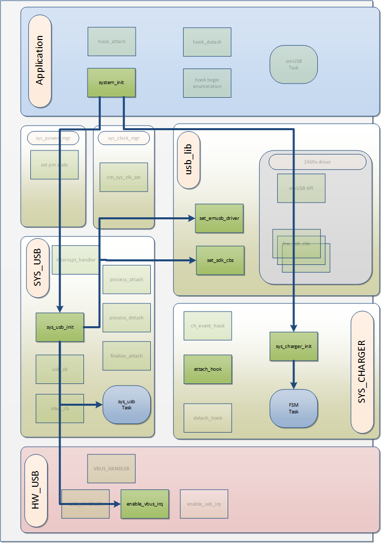
The BLE application is implemented in a FreeRTOS task that is created by the system_init() function. system_init() runs at the highest priority at startup and is also responsible for starting the BLE manager and BLE adapter tasks.
The application task has the following flow:
Device initialization and configuration: Start-up BLE, setting device role, device name, appearance and other device parameters.
Attribute database creation (GATT server devices): Creation of services and attributes using the BLE service framework. This must be done after (1) to prevent deletion of the attribute database.
Air operation configuration and initiation: BLE peripheral devices usually end-up advertising and BLE central devices end-up scanning and/or attempting to connect to another device.
The infinite for(;;) loop, which is the application’s event handling loop. The application has been set-up as desired and now it is waiting for BLE events to respond to, like connections or write requests.
The BLE adapter (ad_ble_task) must have a higher priority than the application task(s) because it runs the BLE Host stack scheduler and it handles time critical tasks.
Most of the BLE applications use the FreeRTOS task notifications mechanism to block. ble_adv_demo is the simplest application and is the only project that does not use this mechanism. Instead, it just blocks on the BLE manager’s event queue.
In addition to the BLE-related functionality most projects also use other system modules, like software timers or sensors. In this case, the application usually defines callback functions to be triggered on these system events or interrupts. These callback functions should use task notifications to unblock the application task which can then handle the event or interrupt in the application task’s context (under its for(;;) loop).
Warning
Calling a BLE API function inside a callback function triggered on a timer expiry will execute the BLE API function in the timer’s task context. Calling other functions in the callback functions can also have implications on real time performance or in corrupting the small stack used by the timer task.
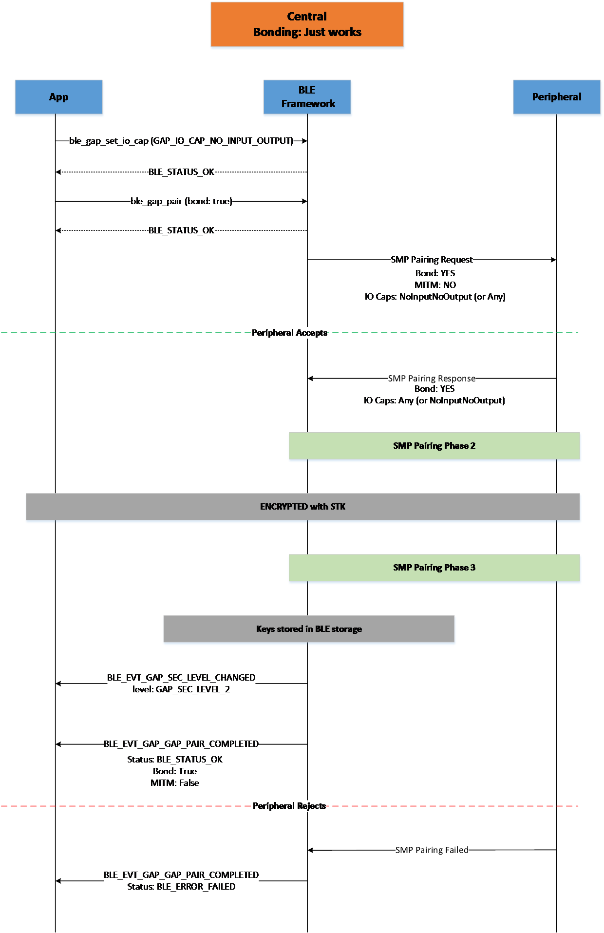
The Bluetooth specification defines the security options for device authentication and link encryption. These aspects of security are handled seamlessly by the BLE Framework. The API in Table 69 is able to set-up security, initiate pairing, do a security request or set-up encryption using previously exchanged keys. Most details of the procedures will be handled internally by the BLE Framework and the application will be notified only if intervention is needed or when the procedure is completed. These options will be described in detail in Section 5.1.9.2 and Section 5.1.10.
The generation and storage of the security keys and other bonding information is also handled by the BLE Framework. Persistent storage can also be used to enable storage of the security keys and bonding data info in the flash. The BLE Framework can then retrieve this information after a power cycle and use it to restore connections with previously bonded devices. This is described in Section 5.1.12.
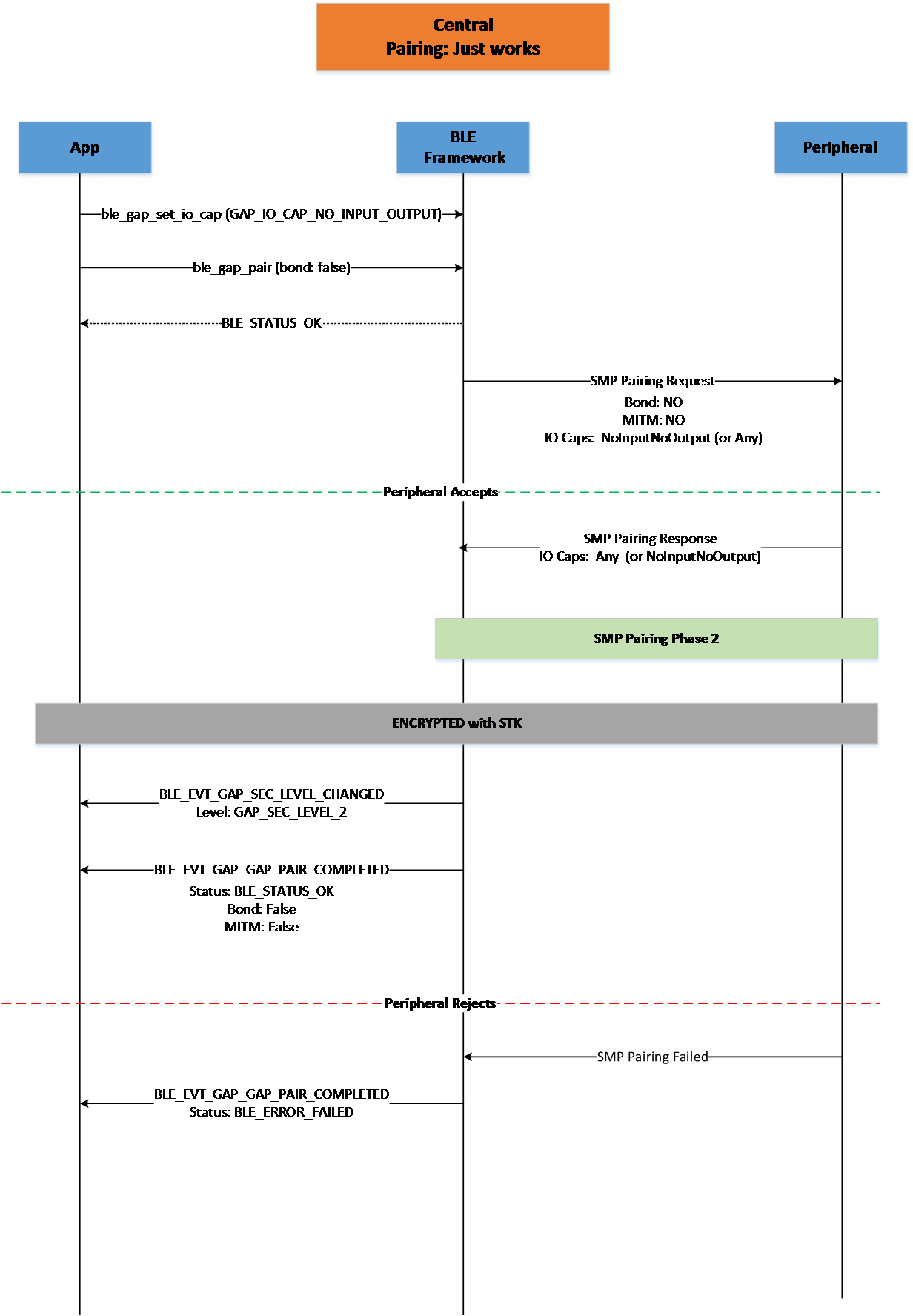
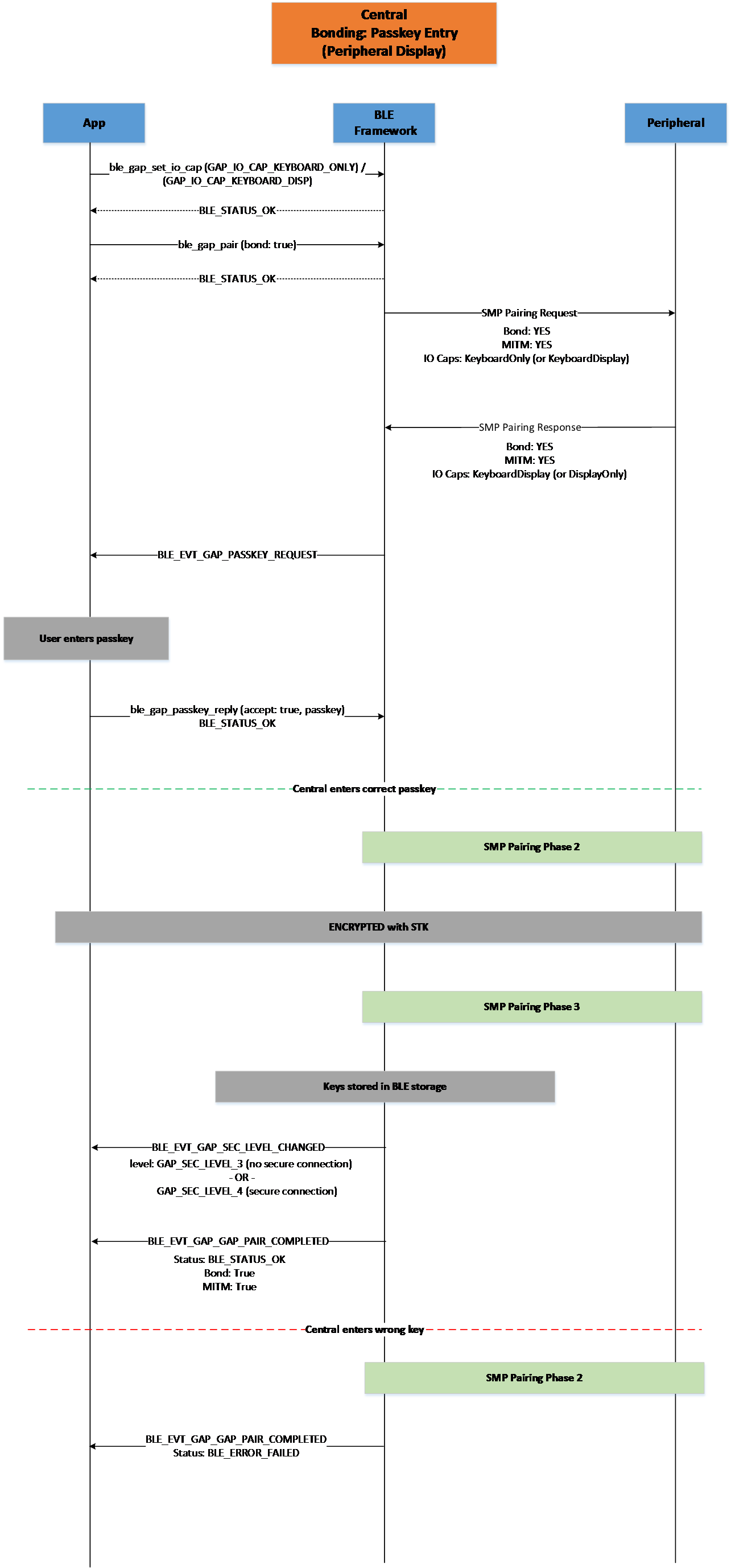
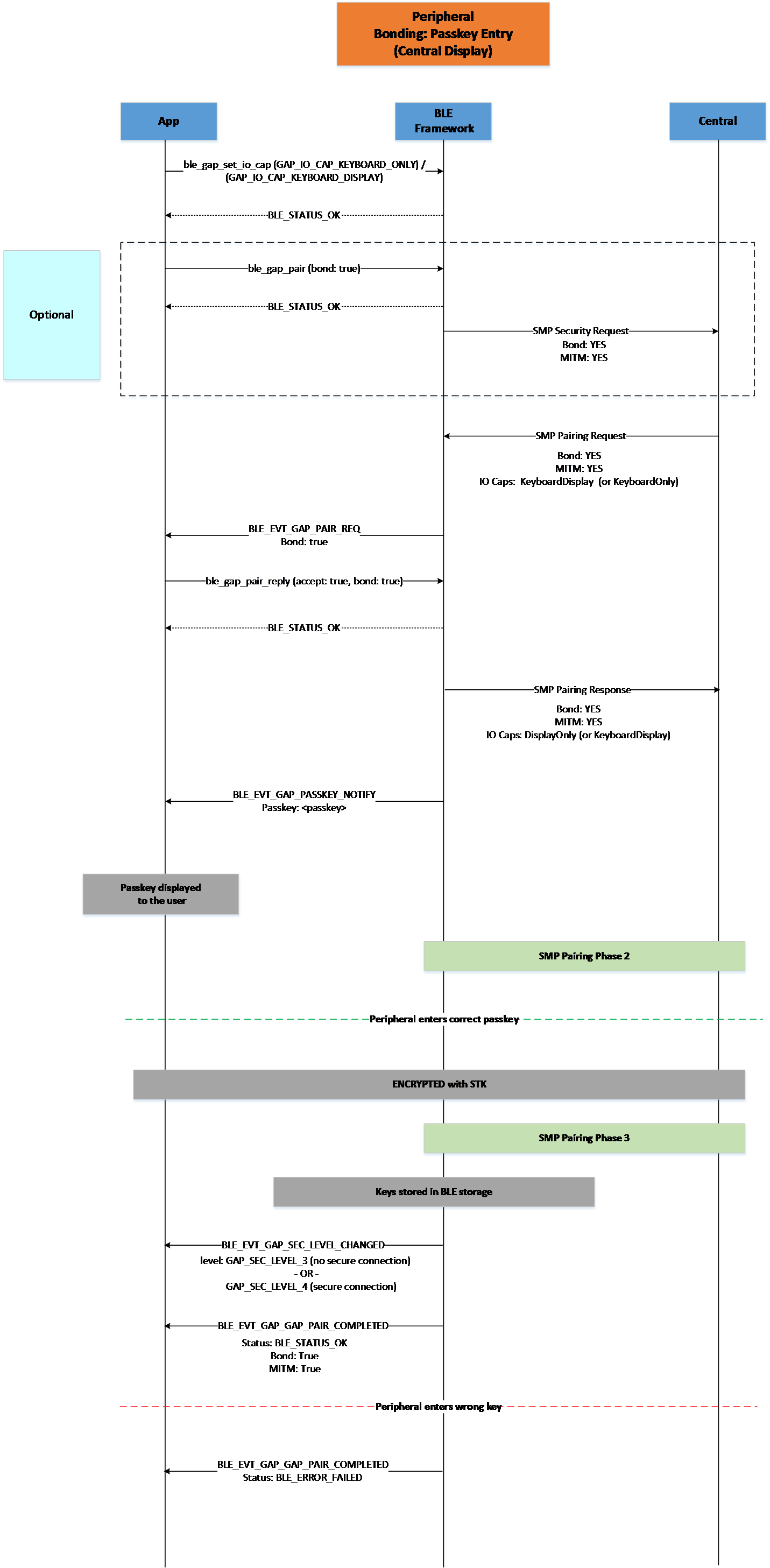
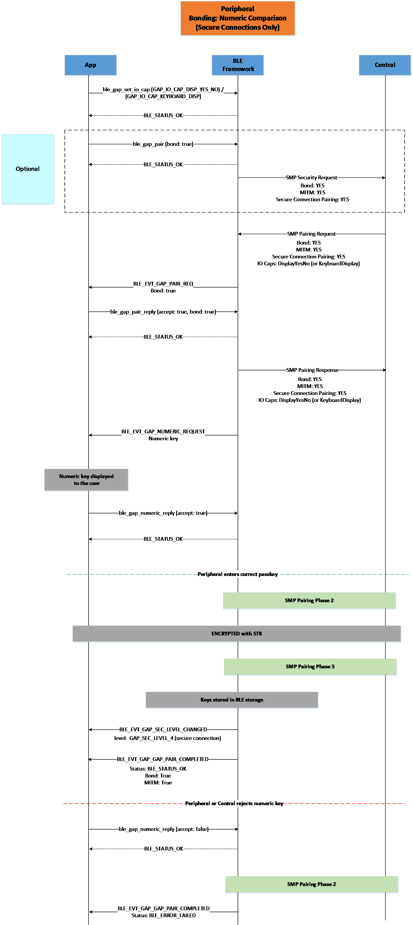
LE Secure Connections pairing is supported and enabled by default by the SDK using the API described in Section 5.1.9.2, LE Secure Connections pairing will be used if the connected peer supports the feature without the need for the application to specifically request it. If the combination of the devices’ capabilities result in a numeric comparison pairing algorithm (introduced and used for the LE Secure Connections pairing), the application will be notified of a numeric comparison request during pairing by the reception of a BLE_EVT_GAP_NUMERIC_REQUEST event and should respond using ble_gap_numeric_reply() function.
If the application needs to use only LE Legacy Pairing and disable LE Secure Connections support in the SDK, it should define dg_configBLE_SECURE_CONNECTIONS macro to 0 in the application config file.
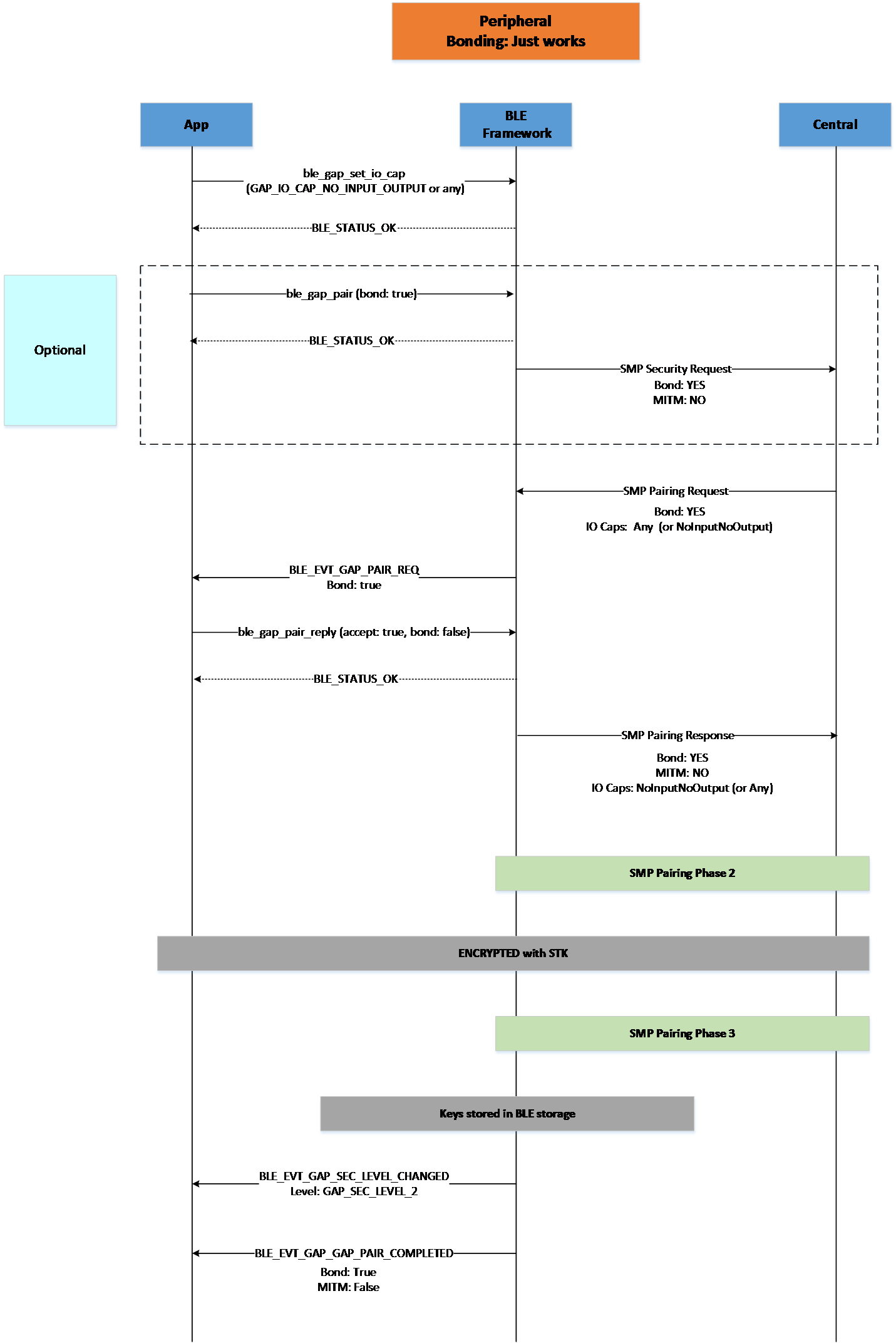
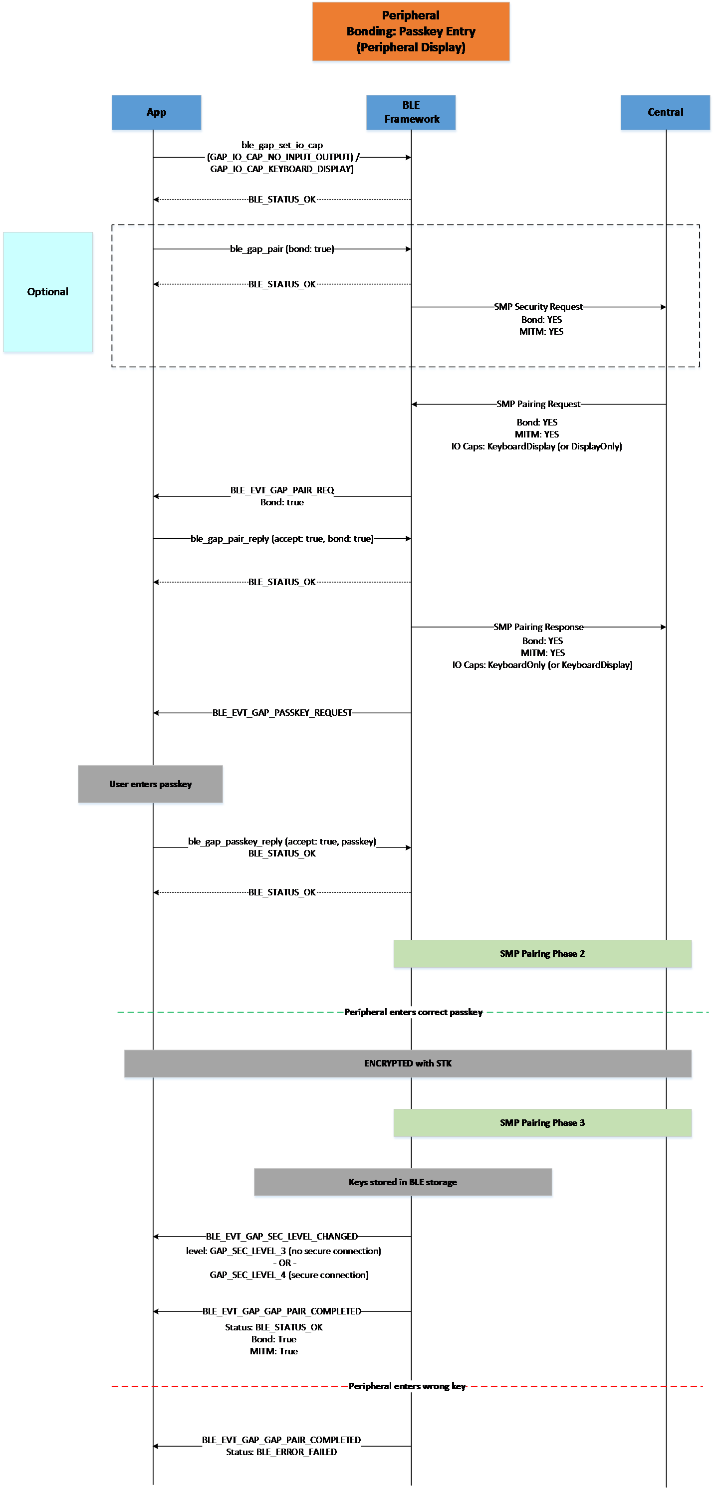
Initiate a pairing or bonding procedure with a connected peer. Depending on whether the device is master or slave on the connection, this call will result either in a pairing or a security request respectively.
ble_gap_pair_reply()
Reply to a received BLE_EVT_GAP_PAIR_REQ event. This event will only be received by a peripheral device when the central peer has initiated a pairing procedure, so this function should only be called by a peripheral application and only after a BLE_EVT_GAP_PAIR_REQ event has been received.
ble_gap_passkey_reply()
Reply to a received BLE_EVT_GAP_PASSKEY_REQUEST event. This event will be received if the combination of the devices’ input/output capabilities results in a passkey entry pairing algorithm. The application should use this function to submit the passkey for the pairing procedure to proceed.
ble_gap_numeric_reply()
Reply to a received BLE_EVT_GAP_NUMERIC_REQUEST event. This event will be received if the combination of the devices’ input/output capabilities results in a numeric comparison pairing algorithm. The application should use this function to accept or reject the numeric key for the pairing procedure to proceed. This should be only used if LE Secure Connections are enabled.
ble_gap_set_sec_level()
Set the security level for a connection. If the device is already bonded, the existing Long Term Key (LTK) will be used to set-up encryption. If the device is not bonded, a pairing or a security request will be triggered (depending on whether the device is master or slave on the connection) with the bond flag set to false.
ble_gap_get_sec_level()
Get the security level currently established on a connection.
ble_gap_unpair()
Unpair a previously paired or bonded device. This will also remove security keys and bonding data info currently present in BLE storage.
Pairing request received by a connected peer. Member <bond> indicates if the peer has requested a bond (that is, exchange of long term security keys). The application should use ble_gap_pair_reply() to respond to this request.
BLE_EVT_GAP_PAIR_COMPLETED
ble_evt_gap_pair_completed_t
A previously requested pairing procedure has been completed. Member <status> indicates the completion status of the procedure, while members <bond> and <MITM> indicate if a bond was established with the peer and if MITM (Man In The Middle) protection has been enabled on the connected link.
BLE_EVT_GAP_SECURITY_REQUEST
ble_evt_gap_security_request_t
Security request received by a connected peripheral peer. Members <bond> and <MITM> indicate if a bond and MITM protection have been requested by the peer. The application may use ble_gap_pair() to initiate pairing with the peer.
BLE_EVT_GAP_PASSKEY_NOTIFY
ble_evt_gap_passkey_notify_t
A passkey has been generated during a pairing procedure. This event will be received if the application has display capability. Member <passkey> contains the passkey that should be displayed to the user and entered by the peer for the pairing procedure to continue.
BLE_EVT_GAP_PASSKEY_REQUEST
ble_evt_gap_passkey_request_t
A passkey has been requested during a pairing procedure. This event will be received if the application has keyboard capability. The application should use ble_gap_passkey_reply() to respond to this request using the passkey entered by the user.
BLE_EVT_GAP_NUMERIC_REQUEST
ble_evt_gap_numeric_request_t
A numeric comparison has been requested during a pairing procedure. This event will be received if the application has keyboard or Yes/No and display capability. The application should use ble_gap_numeric_reply() to respond to this request using the accept or reject input entered by the user.
BLE_EVT_GAP_SEC_LEVEL_CHANGED
ble_evt_gap_sec_level_changed_t
The security level has been changed on an established link. Member <level> contains the security level that has been reached. This will be received after a pairing or an encryption procedure has been successfully completed.
BLE_EVT_GAP_SET_SEC_LEVEL_FAILED
ble_evt_gap_set_sec_level_failed_t
Setting the security level on an established link using ble_gap_set_sec_level() has failed. Member <status> indicates the reason for the failure. This will be received after an initiated encryption procedure has been unsuccessful. This may indicate that pairing should be requested again for the connected peer (for example, the peer may have lost the previously exchanged security keys).
The Bluetooth specification defines the way by which a device can request a remote device to make a specified change in
its TX power level on a given PHY. The response of the peer device contains a value that indicates an acceptable reduction in the power
level that allows the local device to further reduce its transmit power level to the minimum level possible.
The local and remote devices can also share their current transmit power levels. This way they can also calculate the link path loss between them.
This 5.2 BLE Feature is supported and enabled by default by the SDK using the API described in Section 5.1.11.2
The BLE specification defines that the radio receiver can have an RSSI Golden Range that it prefers the incoming signal to remain within.
This functionality is supported and so the local controller adjusts automatically the peer’s TX power to bring RSSI to its preferred value inside this Golden Range.
The local device continuously monitors the RSSI and if it is below the minimum or above maximum acceptable values of the RSSI
it uses the Power Control Request procedure to request an increase or decrease the TX power level of the peer device. This procedure is done automatically by the local device. The application
can be informed about the changes in the local and the remote TX power levels by using the ble_gap_tx_power_report_en() command. The changes in the TX power level are then reported to the application by the
BLE_EVT_GAP_TX_PWR_REPORT event.
The default values of the RSSI Golden Range can be seen in Table 74.
Reading of the local transmit power has been completed. Member <phy> indicates the PHY, member <curr_tx_pwr_lvl> indicates the current transmit power level (dBm) while member <max_tx_pwr_lvl> indicates the maximum transmit power level.
BLE_EVT_GAP_TX_PWR_REPORT
ble_evt_gap_tx_pwr_report_t
Reports that the local or remote transmit power has changed or that a ble_gap_remote_tx_power_get() command has been completed. Member <reason> indicates the reason the of event and device (local or remote) , member <phy> indicates the PHY involved (which might not be the current transmit PHY for the device), member <tx_pwr_lvl> indicates the value of TX power level (dBm), member <tx_pwr_lvl_flag> indicates if the TX power level is min or max while the member <delta> indicates the actual change in the TX power level.
BLE_EVT_GAP_PATH_LOSS_THRES
ble_evt_gap_path_loss_thres_t
Reports a path loss threshold crossing. Member <curr_path_loss> indicates the current path loss value while member <zone_enter> indicates which zone path loss has entered.
BLE Storage is the module that implements storage functionality for information related to connected and bonded peers, like security keys, CCC descriptors configuration and application-defined values. BLE Storage can maintain the list of connected and bonded devices both in RAM and in persistent storage (for example, in the flash). By default, devices are managed in RAM only and persistent storage must be explicitly enabled in the application’s configuration by defining macro CONFIG_BLE_STORAGE. Device data is then stored using Non-Volatile Memory Storage (NVMS) on the generic partition (see Section 4.2 for details).
Two kinds of data are stored:
Device pairing data (exchanged keys and related information).
Application-defined data managed using the BLE storage API (only the values with the ‘persistent’ flag set are stored in flash, for example CCC descriptor values).
Persistent storage can be enabled by the application by adding the
following entries in the application’s custom configuration file:
// enable BLE persistent storage#define CONFIG_BLE_STORAGE// enable Flash and NVMS adapters with VES (required by BLE persistent storage)#define dg_configFLASH_ADAPTER 1#define dg_configNVMS_ADAPTER 1#define dg_configNVMS_VES 1
The maximum number of bonded devices can be set using the defaultBLE_MAX_BONDED macro (defined to 8 by default). If the application attempts to bond more devices than its allowed, an error will be returned. This error should be handled by the application. It can then either unpair one of the currently bonded devices (using ble_gap_unpair() API function) or perform pairing without bonding.
Technical details on the BLE Storage implementation can be found in the
following readme file:
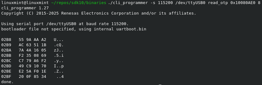
To enhance secure storage and comply with the Radio Equipment Directive (RED), SDK10 introduces support for generating and storing a Device Unique Symmetric Key (DUSK). This per-device random key is generated using the TRNG hardware accelerator and stored securely in a designated OTP memory slot. It is used by the secure store functionality to:
Encrypt bonding data managed by the BLE Manager and stored in QSPI flash
Allow applications to securely store and access encrypted user data
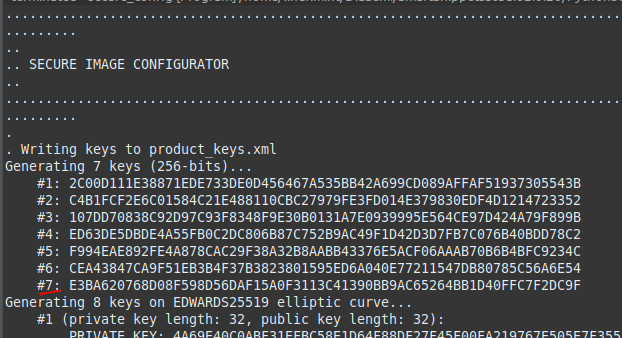
To avoid overwriting the DUSK slot, the generate_keys.py under utilities/python_scripts/secure_image script has been updated to prompt users before generating the 8th symmetric user key.
To support the DUSK feature, the generate_keys.py script has been updated. This script typically generates eight 256-bit symmetric user keys for image signature verification and decryption, storing them in the OTP’s User Data Encryption Keys – Payload section.
Since the last slot is now reserved for the Device Unique Symmetric Key (DUSK), the script has been modified to prompt the user to optionally skip generating the eighth key. This prevents accidental overwriting of the DUSK slot during key provisioning.
5.1.13. Logical Link Control and Adaptation Layer Protocol
The Logical Link Control and Adaptation Layer Protocol, referred to as
L2CAP provides connection-oriented and connectionless data services to
upper layer protocols with protocol multiplexing capability and
segmentation and reassembly operation. As referred in [Ref_02], L2CAP permits
higher level protocols and applications to transmit and receive upper
layer data packets (L2CAP Service Data Units, SDU) up to 64 kilobytes in
length. L2CAP also permits per-channel flow control and retransmission.
The L2CAP layer provides logical channels, named L2CAP channels, which
are multiplexed over one or more logical links. Each one of the
endpoints of an L2CAP channel is referred to by a channel identifier
(CID).
L2CAP channels may operate in one of five different modes as selected
for each L2CAP channel. The modes are:
Basic L2CAP Mode (equivalent to L2CAP specification in Bluetooth
v1.1)
Flow Control Mode
Retransmission Mode
Enhanced Retransmission Mode
Streaming Mode
LE Credit Based Flow Control Mode
The null CID (0x0000) is never used as destination endpoint. Identifiers
from 0x0001 to 0x003F are reserved for specific L2CAP functions. These
channels are referred to as Fixed Channels.
CID 0x0004 is used by the ATT, CID 0x0006 is used by the SMP while CID
is used by the signaling channel.
As referred above, the connection-oriented data channels represent a connection between two devices, where a CID, combined with the logical link, identifies each endpoint of the channel.
Figure 66 illustrates the format of the L2CAP PDU in basic mode.
Figure 66 L2CAP PDU format in Basic L2CAP mode on COC
Summarizing:
L2CAP implementations transfer data between upper layer protocols and
the lower layer protocol.
L2CAP maps channels to Controller logical links, which in turn run
over Controller physical links. All logical links going between a
local Controller and remote Controller run over a single physical
link.
L2CAP is packet-based but follows a communication model based on
channels. A channel represents a data flow between L2CAP entities in
remote devices. Channels may be connection-oriented or
connectionless. Fixed channels other than the L2CAP connectionless
channel (CID 0x0002) and the two L2CAP signaling channels (CIDs
0x0001 and 0x0005) are considered connection-oriented. All channels
with dynamically assigned CIDs are connection-oriented.
The Credit-Based Flow Control is an L2CAP mode of operation that when used, allows both devices involved in the LE connection to have complete control over how many packets the peer device is allowed to send. This is achieved by the use of credits that represent the absolute maximum number of LE frames that the device is willing to accept at a particular moment. The sending entity may send only as many LE-frames as it has credits. If the credit count reaches zero the transmission must stop. If more frames are sent the connection will be closed.
To establish a LE-Credit Based L2CAP connection, the initiator should send a LE Credit-Based connection request, specifying parameters like the Protocol Service Multiplexer (PSM), Maximum Transmission Unit (MTU), Maximum Payload Size (MPS), and the initial number of credits that the remote peer has to send data. The responding device should respond with a LE Credit-Based Connection Response specifying its own MTU, MPS and initial credits value. PSM is 2-byte odd number that can be used to support multiple implementations of a protocol. The valid range for PSM is between 0x80-0xFF. The fixed SIG assigned PSM values are between 0x00 and 0x7F. MTU represents the maximum size of data that the service above L2CAP can send to the remote peer (Maximum size of an SDU – Service Data Unit). MPS is the maximum payload size that an L2CAP entity can receive from the lower layer, and it is equivalent to the maximum PDU payload size. Each MPS corresponds to one credit. One SDU (of size MTU) can be fragmented to one or more PDUs (of size MPS). If the SDU length field value exceeds the receiver’s MTU, the receiver shall disconnect the channel. If the payload length of any LE-frame exceeds the receiver’s MPS, the receiver shall disconnect the channel. If the sum of the payload lengths for the LE-frames exceeds the specified SDU length, the receiver shall disconnect the channel. After the LE Credit-Based connection request and response frames are received or exchanged, the two entities agree to use the minimum values of MTU and MPS.
As an example, consider two devices that use the following values during the Credit-Based connection request/response procedure:
In this scenario, device B can receive PDUs of size at most 23, and SDUs of size at most 250. On the other hand, device A can receive PDUs of size at most 100, and SDUs of size at most 50. Device A can send 20 PDUs to device B, and should stop until device B updates the available credits. This update could be performed any time during the connection. If device A was to transmit an SDU of size 100 bytes (MTU), it would be fragmented to 5 PDUs of data sizes 21, 23, 23, 23 and 10 respectively. This transmission would consume 5 credits (one credit for every PDU that could be received from device B). Note that the usable payload size of the first PDU is 2 bytes less than the value of MPS as the first LE-frame contains a 2-byte field specifying the total length of the SDU. This is true only for the first frame. In the same manner, the transmission of a 23-byte SDU would require two credits and two PDUs of size 21 and 2 bytes respectively whereas the transmission of a 21-byte SDU would require just one PDU. Maximum SDU length (MTU) can be specified using the ble_gap_mtu_size_set() API call.
Create a l2cap connection oriented channel with remote peer. Connection establishment will be signaled using BLE_EVT_L2CAP_CONNECTED event.
ble_l2cap_listen()
Create a connection oriented channel listening for incoming connections. Incoming connection will be signaled using BLE_EVT_L2CAP_CONNECTED event.
ble_l2cap_listen_defer_setup()
Create a connection oriented channel listening for incoming connections. Incoming connection will be signaled using BLE_EVT_L2CAP_CONNECTION_REQ event.
ble_l2cap_connection_cfm()
Accept or reject incoming connection. Accepted connection will be signaled using BLE_EVT_L2CAP_CONNECTED event.
ble_l2cap_stop_listen()
Stop listening for incoming connections.
ble_l2cap_disconnect()
Disconnect an established L2CAP channel.
ble_l2cap_send()
Send data on channel, response code is signaled using the BLE_EVT_L2CAP_SENT event.
ble_l2cap_add_credits()
Provide additional credits to remote peer. BLE_EVT_L2CAP_REMOTE_CREDITS_CHANGED event will be signaled on the remote peer.
Table 78 L2CAP COC Events – received through ble_get_event() - ble_l2cap.h
Event
Argument
Description
BLE_EVT_L2CAP_CONNECTED
ble_evt_l2cap_connected_t
Channel connected. Members <local_credits> and <remote_credits> specify the initial credits for both sides of connections, whereas <mtu> indicates the negotiated MTU value (Maximum SDU length).
BLE_EVT_L2CAP_CONNECTION_FAILED
ble_evt_l2cap_connection_failed_t
Channel connection failed. Member <status> indicates the reason that connection failed.
BLE_EVT_L2CAP_CONNECTION_REQ
ble_evt_l2cap_connection_req_t
Request connection. Members refer to connection parameters e.g. <psm>, <scid>, <dcid>, <mtu> refer to LE protocol/service multiplexer, source CID, destination CID, negotiated MTU respectively.
BLE_EVT_L2CAP_DISCONNECTED
ble_evt_l2cap_disconnected_t
Channel disconnected. Member <reason> indicates the reason of disconnection.
BLE_EVT_L2CAP_SENT
ble_evt_l2cap_sent_t
Data sent on channel. <remote_credits> member specifies the remaining number of credits that are available for transmission.
BLE_EVT_L2CAP_REMOTE_CREDITS_CHANGED
ble_evt_l2cap_credit_changed_t
Available remote credits changed on channel. <remote_credits> member specifies the remaining number of credits that are available for transmission.
BLE_EVT_L2CAP_DATA_IND
ble_evt_l2cap_data_ind_t
Data received on channel. <local_credits_consumed> member specifies the local credits consumed for the received data.
For Bluetooth Core versions 4.0 and 4.1 the maximum Packet Data Unit (PDU) size was 27 octets. Bluetooth Core version 4.2 introduced an important enhancement, namely LE Data Packet Length Extension, which allows for the PDU size to be anywhere between 27 and 251 octets. This means that, for example, the L2CAP layer can now fill up to 247 octets of higher layer data packets in every L2CAP PDU compared to 21 octets with previous Bluetooth Core versions. This significant increase (more than 10 times) in the number of octets of user data sent per packet allows devices to transfer data up to 2.5 times faster than with previous versions. This will be of great benefit to applications that might require transferring large amounts of data such as Over-the-Air (OTA) firmware updates or downloading large data logs from sensors.
For the default PDU size to be extended on an established connection, the Data Length Update procedure must be performed. According to this control procedure, the LL_LENGTH_REQ and LL_LENGTH_RSP PDUs must be exchanged by the connected devices so that each is notified of its peer device’s capabilities. Each device uses these PDUs to report its maximum receive data channel and maximum transmit data channel PDU payload length and PDU time. After this update procedure, the PDU size for each direction of the connection’s data path is set by both controllers to the minimum of the values exchanged.
The DA1469x supports the LE Data Length Extension feature, so the values for the Receive and Transmit Data Length are set by default to the maximum allowed, which is 251 octets. The DA1469x controller when configured as a BLE central device will initiate a Data Length Update upon a new connection if the peer device’s controller supports this feature. The BLE Manager will use the values defined by dg_configBLE_DATA_LENGTH_RX_MAX and dg_configBLE_DATA_LENGTH_TX_MAX macros for this initial Data Length Update negotiation.
Set the maximum Transmit data length and time for an existing connection or the preferred Transmit data length for future connections (that is, the Transmit data length to be used in future data length update negotiations). Connection data length change will be signaled using BLE_EVT_GAP_DATA_LENGTH_CHANGED event.
Set the maximum Receive Data Channel PDU Payload Length. Unless ble_gap_data_length_set() is used by the application, this will define the Receive data length present in the LE Data Length Update negotiations done by the device.
dg_configBLE_DATA_LENGTH_TX_MAX
251
Set the maximum Transmit Data Channel PDU Payload Length. Unless ble_gap_data_length_set() is used by the application, this will define the Transmit data length present in the LE Data Length Update negotiations done by the device.
Table 81 LE Data Length Events – fetched using ble_get_event() - ble_gap.h
Event
Argument
Description
BLE_EVT_GAP_DATA_LENGTH_CHANGED
ble_evt_gap_data_length_changed_t
Data Length changed for specified connection. Members <rx_length>, <rx_time>, <tx_length> and <tx_time> specify the values obtained after an LE Data Length Update negotiation (each direction’s data length is typically set to the minimum of the values reported by the connected devices).
BLE_EVT_GAP_DATA_LENGTH_SET_FAILED
ble_evt_gap_data_length_set_failed_t
Data Length Set operation failed. Member <status> indicates the reason the set operation failed.
Bluetooth Core versions up to 4.2 supported only the mandatory bit rate of 1 megabit per second (Mb/s), which is referred to as the LE 1M PHY. Bluetooth Core version 5.2, which is implemented in Renesas DA1469x product family, also supports the optional bit rate of 2 Mb/s, which is referred to as the LE 2M PHY. This feature is implemented by the LE controller and it can be configured using the API described in Section 5.1.15.1 and Section 5.1.15.2, although additional configuration is not mandatory; the LE controller will handle PHY update procedures seamlessly and will inform the application of any changes in the PHY configuration regardless of which side initiated the PHY update procedure.
Get the transmitter and receiver PHY preferences set for an existing connection or for all future connections. The changes in PHY configuration for a given connection will be signaled using BLE_EVT_GAP_PHY_CHANGED event.
ble_gap_phy_set()
Set the transmitter and receiver PHY preferences for an existing connection or for all future connections. Completion of the PHY set operation will be signaled using BLE_EVT_GAP_PHY_SET_COMPLETED event and possible change in PHY configuration for a given connection will be signaled using BLE_EVT_GAP_PHY_CHANGED event.
Table 83 LE 2M Events – fetched using ble_get_event() - ble_gap.h
Event
Argument
Description
BLE_EVT_GAP_PHY_CHANGED
ble_evt_gap_phy_changed_t
PHY configuration changed for the specified connection. Members <tx_phy> and <rx_phy> specify the current configuration for the transmitter and received PHY respectively. This event is received only after a change in one or both of the transmitter and receiver PHY configurations.
BLE_EVT_GAP_PHY_SET_COMPLETED
ble_evt_gap_phy_set_completed_t
PHY set operation has completed. This will be received following a ble_gap_phy_set() call. Member <status> indicates the status of the set operation.
The BLE Software in the SDK consists of three modules:
BLE manager: Provides the interface to the BLE functionality of the chip. The application task uses the BLE API to interface with the BLE manager. The BLE manager is a task that stands between the application and the BLE adapter. It uses the BLE adapter to interface with the BLE Stack.
BLE adapter: The system task that provides the interface to the BLE Stack. It runs the BLE Stack internal scheduler, receives the commands or the replies to events from the BLE manager, and passes BLE Stack events to the BLE manager. BLE core functionality is implemented by the BLE adapter task.
BLE Stack: The software stack that implements the Link Layer and the BLE Host stack, specifically the Logical Link Control and Adaptation Protocol (L2CAP), the Security Manager Protocol (SMP), the Attribute Protocol (ATT), the Generic Attribute Profile (GATT) and the Generic Access Profile (GAP).
Note
The BLE Stack software is run under the BLE adapter’s task context, which instantiates and initializes the stack.
The two BLE system tasks have by default a higher priority than application tasks in the SDK.
Note
Application developers should always make sure BLE adapter and BLE manager tasks always have a higher priority than application tasks.
The BLE adapter runs the BLE Stack scheduler, which dispatches all the messages between the BLE Stack’s different layers and calls the appropriate handlers. For example, when an application uses API ble_gatts_send_event() to send a GATT notification, this will result in a propagation of messages between the BLE manager, the BLE adapter and several BLE Stack’s internal layers until it reaches a transmission buffer and, eventually, the air.
In DA1469x the LE controller runs independently from the application. However, the BLE system tasks (BLE adapter, BLE manager) still need to run regularly to make sure BLE data are transmitted and handled in a timely manner.
When the application is not making any BLE API calls and no data are exchanged with the peer, the BLE adapter will typically block until it is needed to either retrieve a message from or send a command to the BLE Host.
In some scenarios the BLE manager and the BLE adapter will communicate with messages without notifying the application. For example, upon connection with a peer that uses a resolvable private address, the BLE manager will attempt to resolve it using known devices IRKs. In this case the BLE manager and BLE adapter will have more running slots.
There are also other cases when the BLE framework will require a reply from the application when, for example, a pair request or a write request is received from the peer. Again, in these cases the BLE adapter and BLE manager will have to run more times in a period between two connection events.
As the Attribute protocol is strict when an attribute request such as a read or a write request is received, the BLE Stack’s GATT layer will switch to a busy state for as long as the request is not completed/handled. In the case of a write request or a read request of an attribute whose value is to be provided by the application, then the application will have to confirm these operations using ble_gatts_read_cfm() or ble_gatts_write_cfm() respectively (after receiving BLE_EVT_GATTS_READ_REQ or BLE_EVT_GATTS_WRITE_REQ). In this case, other GATT operations, such as notification sending, will be queued until this request is confirmed.
The simplest BLE project in the DA1469x SDK is ble_adv demo which is found in the folder <SDK_ROOT_PATH>/projects/dk_apps/demos/ble_adv. The application starts the device as a peripheral, sets the device name and advertising data and starts advertising. Code 46 is an extract from main.c.
// Start BLE module as a peripheral deviceble_peripheral_start();// Set device nameble_gap_device_name_set("Dialog ADV Demo",ATT_PERM_READ);// Set advertising datable_gap_adv_data_set(sizeof(adv_data),adv_data,0,NULL);// Start advertisingble_gap_adv_start(GAP_CONN_MODE_UNDIRECTED);
No BLE service is added, and the ones exposed are just GAP and GATT
services. The infinite loop that implements the lifetime behavior of the
application uses just ble_get_event(true) to block indefinitely on the
BLE manager’s event queue. As soon as an event is posted there, the task
unblocks and handles it using a switch case. Code 47 is located in
main.c.
for(;;){ble_evt_hdr_t*hdr;/* notify watchdog on each loop */sys_watchdog_notify(wdog_id);/* suspend watchdog while blocking on ble_get_event() */sys_watchdog_suspend(wdog_id);/* * Wait for a BLE event - this task will block * indefinitely until something is received. */hdr=ble_get_event(true);/* resume watchdog */sys_watchdog_notify_and_resume(wdog_id);if(!hdr){continue;}switch(hdr->evt_code){caseBLE_EVT_GAP_CONNECTED:handle_evt_gap_connected((ble_evt_gap_connected_t*)hdr);break;caseBLE_EVT_GAP_DISCONNECTED:handle_evt_gap_disconnected((ble_evt_gap_disconnected_t*)hdr);break;caseBLE_EVT_GAP_PAIR_REQ:{ble_evt_gap_pair_req_t*evt=(ble_evt_gap_pair_req_t*)hdr;ble_gap_pair_reply(evt->conn_idx,true,evt->bond);break;}default:ble_handle_event_default(hdr);break;}// Free event bufferOS_FREE(hdr);}
Since the BLE service framework is not used, the only events handled by the application are the three events handled by the switch case: connection, disconnection and pair request. This makes sense for this application as its only purpose is to start a connectable advertising, restart it in case of a disconnection and respond to pair requests from devices that require pairing/bonding upon connection.
Running this project will result in an advertising BLE peripheral device exposing GAP and GATT services. GAP service attributes can be read using any standard BLE central device.
The ble_peripheral project is a good starting point for developing BLE peripheral applications. It is found in folder <SDK_ROOT_PATH>/projects/dk_apps/features/ble_peripheral. Unlike other example projects, it does not implement a specific profile, but instead exposes several BLE services via a GATT server.
The application’s initialization is similar to other projects that implement BLE peripheral applications. It uses the BLE service framework to instantiate several BLE services:
Battery Service (multiple instance)
Current Time Service
Device Information Service
Scan Parameter Service
Renesas Debug Service
Custom User Service
In addition to Bluetooth SIG-adopted services, ble_peripheral project instantiates two more services, Renesas Debug Service and a custom user service.
The Renesas Debug Service can be used to interact with the services that
the application exposes using a Control Point characteristic to write
commands and receive notifications from. A detailed description of the
ways to interact with the Renesas Debug Service is included in the
readme.md file inside the project’s folder.
The custom user service does not define any specific functionality other than using 128-bit UUIDs for services, characteristics and descriptors. This custom service, referred to as myservice in the project source code, is an example of implementing a custom service using BLE API calls to create its attribute database. No specific functionality is defined when one of these attributes is read or written. More details on how to create and use custom services will be given in Section 5.1.23.
After the attribute database is created, the device will end-up
advertising and it will wait for a connection event.
The ble_peripheral project uses the BLE service framework to handle service events, the application also defines handlers for connection, advertising completion and pair request events. The ble_peripheral project stands in terms of its completeness somewhere between the ble_adv demo and an application implementing a full BLE profile like the pxp_reporter.
The services the project will expose can be configured using the file config/ble_peripheral_config.h.
In addition to the projects described in the previous sections, there are several application projects that implement BLE profiles. These projects are more complex and provide a full implementation of BLE applications. As such they provide a good reference on how to combine the BLE functionality with several OS mechanisms, GPIO handling and interfacing with external sensors.
The implemented profiles are located under <SDK_ROOT_PATH>/projects/dk_apps/ble_profiles and listed below:
Apple Media Service (AMS) - Client role
HID over GATT Profile (HOGP) – Device role (hogp_device)
HID over GATT Profile (HOGP) – Host role (hogp_host)
Heart Rate Profile – Sensor role (hrp_sensor)
Heart Rate Profile – Collector role (hrp_collector)
Proximity Profile – Reporter role (pxp_reporter) located under <SDK_ROOT_PATH>/projects/dk_apps/demos
Weight Scale Profile – Weight Scale role (wsp_weightscale)
Apple Notification Center Service (ANCS) - Notification Consumer (NC) role (ancs)
Blood Pressure Profile (BLP) – Blood Pressure Sensor role (blp_sensor)
Table 85 summarizes the API header files of the BLE services implemented by the DA1469x SDK. These files can be found under <SDK_ROOT_PATH>/sdk/interfaces/ble/services/include. The developer can use these APIs to add these services to another project.
The following code segments provide an overview of the initialization required to create a new custom service called XXX. It requires the files xxx.c and xxx.h to be created. A good example to base these on is the dlg_mls service in the Multi-Link demo. This provides a single write only characteristic in the service.
Each service needs a structure containing both the generic ble_service_t structure and any callbacks and characteristic handles required by the service. In the example below for service XXX there is one callback and one characteristic defined.
typedefstruct{ble_service_tsvc;// Core BLE service structurexxx_cb_tcb;// Callback provided by app to xxx// service to process an eventuint16_txxx_char1_val_h;// Declare handle for each characteristic// that can be read or written}xxx_service_t;
The requirements of the initialization function xxx_init() are illustrated below. They key information here is the comments which are explaining what each line is doing.
xxx_service_t*xxx_init(callback1){// Allocate and initialise xxx_service_t structure// Define any callback functions required by the service, write only in this casexxx->svc.write_req=<thisserviceswriterequesthandler>// Create primary service UUID with either 16 or 128 bit valueuuid=ble_uuid_from_string()oruuid=ble_uuid_create16()// add PRIMARY service with X attributesnum_attrs=Xble_gatts_add_service(&uuid,GATT_SERVICE_PRIMARY,num_attrs)// Create characteristic 1 for this service and allocate handle for it in GATT tableble_gatts_add_characteristic(&uuid,GATTproperty,ATTpermissions,size,0,NULL,&xxx->xxx_char1_h)// Set start_h and pass in null terminated variable length list of all characteristic handles in the serviceble_gatts_register_service(&xxx->svc.start_h,&xxx->xxx_char1_h,0);// Calculate end handle for service based on number of attributes in servicexxx->svc.end_h=xxx->svc.start_h+num_attrs;// add the passed in callback function to service structurexxx->xxx_cb1=callback1;// add newly created service to ble frameworkble_service_add(&xxx->svc);// and return handle for the service to the applicationreturn&xxx->svc}
The Renesas BLE API can be used to develop BLE applications. The API header files are located in folder <SDK_ROOT_PATH>/sdk/interfaces/ble/api/include. They are documented in [Ref_04] and are summarized in Table 86.
The DA1469x SDK allows the user to update the software of
the device wirelessly, using the Software Upgrade Over The Air (SUOTA) procedure.
When an update procedure is initiated from an Android or iOS device, a
new firmware image is first transferred to the Flash memory and then the
device reboots to complete the update. The final verification and
activation of the new image is performed by the ROM boot loader on the
next reboot. For more information see Section 5.3.1.
The SUOTA GATT server runs on the DA1469x device and the GATT client on
the Android or iOS device running the SUOTA application.
Important
RED Compliance
The following updates have been implemented in the SUOTA service for the DA1469x series to ensure compliance with the Radio Equipment Directive (RED):
A basic anti-rollback prevention mechanism is incorporated into the SUOTA service for the DA1469x series.
This mechanism compares the firmware version of the current image with that of the new image before proceeding with the update.
Additionally, the CRC field is utilized to provide an enhancement in protection against rollback attempts.
If the version of the new image is lower than the existing one’s, the suota_state_w4_header() returns false rejecting the SUOTA update.
The SUOTA application remains at 0%, and the device disconnects. However, the application remains responsive, allowing for a new SUOTA update to be initiated.
This update introduces the CONFIG_SUOTA_VERSION_CHECK_ENABLE macro, which is enabled by default to provide anti-rollback protection. It allows users to enable or disable the SUOTA firmware version check as needed.
SUOTA now enforces secure connections. Any SUOTA request must originate from a secure connection; otherwise, it will be rejected. This ensures that firmware updates are performed only over trusted, authenticated links.
This section gives a brief description of the SUOTA service, responsible
for performing software upgrades over BLE. A detailed service
characteristic description is given on Table 87.
Using this
characteristic the
GATT client is able
to send commands to the
SUOTA service. Some of
the most commonly used
commands are the
following:
SPOTAR_IMG_SPI_FLASH(
0x13):
Prepare for SUOTA.
Image is going to be
stored to the FLASH
memory.
SPOTAR_REBOOT(0xFD):
Reboot the device.
SPOTAR_IMG_END(0xFE):
Client sent the whole
image. SUOTA service
is allowed to perform
CRC calculations and
other sanity tests to
verify that the image
transfer was
successful.
GPIO MAP
READ
WRITE
4
Used to
specify
GPIO map of
external
FLASH
device.
Currently
not
applicable.
MEM_INFO
READ
4
Stores the
total
number of
bytes
received
until now.
PATCH_LEN
since
version
v1.3
READ
WRITE
2
Specifies
the number
of bytes
that when
received,
will trigger a
notification
back to the
GATT client.
This is
meant to be
used for
flow
control.
The exact
value is
set by the
GATT client
during
SUOTA. The
notification
is
generated
from the
“STATUS”
characteristic
PATCH_DATA
since
version
v1.3
READ
WRITE
WRITE_NO_RE
SP
Exact size
is
specified
by
PATCH_DATA
CHAR_SIZE
This is the
endpoint to
which SUOTA
image data
are sent.
The exact size
is
specified
by the
“PATCH_DATA
CHAR_SIZE”
characteristic,
and
different
values (23
– 509) can
be used
depending
on the
throughput
requirements
STATUS
since
version
v1.3
READ
NOTIFY
1
This
characteristic
is used to
notify the
GATT client of
the status
of the
SUOTA
process.
Status
notifications
are sent to
indicate
error
conditions
(for
example bad
command, or
CRC) or to
allow flow
control
during
SUOTA
process.
L2CAP_PSM
since
version
v1.3
READ
2
This is an
optional
characteristic
that, if
exists,
indicates
that the
SUOTA
service
supports
both SUOTA
over GATT
and SUOTA
over L2CAP
CoC. The
value
indicates
the dynamic
L2CAP
channel on
which the
SUOTA
service is
listening
for
connections.
The absence
of this
characteristic
indicates
that only
SUOTA over
GATT is
supported.
VERSION
since
version
v1.3
READ
1
Indicates
the version
of the
SUOTA
service.
The value
is
retrieved
from the
“SUOTA_VERSION”
definition.
MTU
since
version
v1.3
READ
2
Stores the
current
value of
the MTU,
which is
going to be
either 23
(default),
or a bigger
value, if
MTU
exchange
took place.
This value
can be used
by the GATT
client to
retrieve
the MTU
size (if
such API is
not
available
on its
side) and
write with
optimal
rate to the
“PATCH_DATA”
characteristic.
PATCH_DATA
CHAR_SIZE
since
version
v1.3
READ
2
Specifies
the size of
the
“PATCH_DATA”
characteristic.
CCC
READ
WRITE
1
Client
Characteristic
Configuration
Allows the GATT
client to
enable
notifications
from the
“STATUS”
source.
Once the SUOTA service is discovered on the remote device and the GATT client
has enabled notifications by writing the CCC characteristic, the SUOTA
procedure can be started by issuing the SPOTAR_IMG_SPI_FLASH command.
The write command executes successfully only if:
No more than one device is currently connected to the SUOTA enabled
device
The application hosted in the SUOTA enabled device allows the upgrade
to take place
There is enough memory to allocate the internal working buffers
If any of the above restrictions is violated, then command fails and an
error notification is sent back to the GATT client (status SUOTA_SRV_EXIT).
After a successful command execution the service is able to receive data
either over GATT or L2CAP CoC layer (if the L2CAP_PSM characteristic is
available).
The GATT client can use the value of the characteristic MTU to perform ATT
write commands to the characteristic PATCH_DATA with optimal size if
the GATT Client (mobile phone) has no API to find the optimal packet size.
It is also possible for the GATT client to retrieve the size of the PATCH_DATA
characteristic by reading the PATCH_DATA_CHAR_SIZE characteristic.
Following this, the GATT client should specify the value of the patch_len
variable by writing the PATCH_LEN characteristic. PATCH_LEN specifies
the number of bytes that once received, will trigger a notification back to
the GATT client. This kind of flow control could be used to
avoid flooding the SUOTA enabled device with too much image data. The
bigger the value, the better the throughput, since notifications are
going to be generated less frequently and therefore the number of missed
connection events (where flow has stopped waiting for the notification)
is decreased.
For example, if patch_len is set to 500 bytes, notifications will
be sent to the GATT client when byte ranges 1-500, 501-1000, 1001 – 1500 etc.
are received. Following the Bluetooth low energy specification, the
maximum number of bytes that can be written to the PATCH_DATA
characteristic with a single ATT write command is the minimum of MTU – 3
and the size of the PATCH_DATA characteristic.
When the whole image has been sent, the GATT client should issue the
SPOTAR_IMG_END command to indicate this to the SUOTA service. The
service is going to perform some sanity checks to verify that image
transfer took place without errors, and then it is going to generate the
appropriate status notification (SUOTA_CMP_OK on success,
SUOTA_APP_ERROR or SUOTA_CRC_ERR on error).
Finally, the GATT client could issue an SPOTAR_REBOOT command to force a
device reboot. This step is optional, but it is highly recommended.
Note
The PATCH_DATA, PATCH_DATA_CHAR_SIZE and PATCH_LEN characteristics
are only relevant when SUOTA over GATT is taking place. When L2CAP
CoC are used, a connection should be established to the L2CAP_PSM
channel via L2CAP CoC and the flow is controlled using L2CAP credits.
SUOTA service assigns enough credits to ensure that flow won’t stop
during the upgrade. Notifications relevant to the PATCH_LEN
characteristic are not sent during image transfer, but all other
notifications are still valid.
Build the pxp_reporter application using the DA1469x-00-Release_QSPI_SUOTA configuration.
A new image named pxp_reporter.img is also created under
DA1469x-00-Release_QSPI_SUOTA folder.
5.2.4.3. Perform the SUOTA using the mobile application
Download the Renesas SUOTA application from Google PlayStore or Apple
App Store.
Copy pxp_reporter.img to an Android phone or tablet or to an
iOS device and place it into the SUOTA folder. The folder is
automatically created, if it does not exist, on the device by running
the “SUOTA” application. On Android it is located at the root
directory of the “Internal Storage” drive.
Launch the Renesas SUOTA application on the Android phone and select the DA1469x device you want to update.
Figure 77 When file upload is finished, press “Close”
5.2.4.4. Performing SUOTA upgrade using two DA1469x devices
This section describes the procedure for performing SUOTA using two
DA1469x devices.
One acting as the BLE central. It performs as the SUOTA
image transmitter running ble_suota_client application.
The SUOTA image will be stored in the NVMS_BIN_PART NVMS partition.
One acting as the BLE peripheral. It performs as the
SUOTA image receiver, running pxp_reporter application.
Using this setup, it is possible to test both SUOTA methods (over GATT
and over L2CAP Connection-Oriented Channels) without using any phone.
The image to be transferred is stored in the NVMS_BIN_PART partition
in the Flash memory of the BLE central device.
5.2.4.4.1. Preparing the SUOTA enabled device pxp_reporter
5.2.4.4.6. Performing the software upgrade procedure
When the previous procedure has finished, the two DA1469x devices are
ready to communicate. To perform SUOTA on the PXP Reporter device, the
following steps should be followed:
A serial terminal is needed to connect to the ble_suota_client
device and perform the SUOTA. In the example below, “Real Term”
is used for this purpose. Configure the serial terminal as follows:
The ble_suota_client device starts scanning for available
devices immediately (Figure 82). In this in example, from the devices
listed Figure 82, the pxp_reporter device, is the
device with sequence number [01].
As soon as the pxp_reporter device is found, the
scanning operation can be stopped with the following command:
>scanstop
A connection to the pxp_reporter device can be
initiated with the command:
>connect1
The first argument of the “connect” command refers to the device index
on the scan result list. Once a connection is established, the
application automatically queries the remote device for available
services and device information. The characteristic values of the Device
Information Service (DIS) are read. The following output is printed on
the terminal:
The presence of “L2CAP PSM” indicates that the remote device supports
SUOTA and over-L2CAP COC.
To update a device supporting L2CAP COC over L2CAP, issue the
update command. To update the same device over GATT, issue the
update gatt command. If the remote device does not support L2CAP
COC (“L2CAP PSM” is not displayed), both update and update
gatt commands begin SUOTA over GATT.
>updategatt
Figure 84 Updating with new image the loader device
After the image transfer has been completed, the remote device
disconnects and reboot as shown in Figure 85.
When the pxp_reporter device reboots, execution of the new image begins.
The software upgrade has finished. Now the pxp_reporter
device should start advertising as <RenesasPXReporter>. To
verify that, perfom the scan operation again by issuing the scanstart command.
>scanstart
Figure 86 Verifying that loader is running PX Reporter
The Boot ROM code is executed by SYSCPU (Cortex-M33) after a POR or HW Reset. As an additional capability it can be executed after wakeup when the RESET_ON_WAKEUP feature is configured.
The following booting options are supported:
Boot from cached QSPI FLASH without any security features, configuration script (CS) in OTP
Boot from cached QSPI FLASH without any security features, configuration script (CS) in FLASH
Boot from cached QSPI FLASH with security features, configuration script (CS) in OTP
Boot from UART without FLASH or security features
In case neither Flash nor UART is available, the booter remains in an infinent loop.
The Configuration Script (CS) is a table of up to 256 32-bit entries. System can boot without CS but if it exists it is stored either in Flash or OTP. The booter expects CS to start at
address 0x00000000 of flash or at 0x00000C00 of OTP. It contains information related to booter, like Product header location, the development mode flag, entries which can be used by SDK
or application software to apply some values to specific registers (address value pair) or to use them as trim values for a subsystem. The address value pair entry in CS is a way to enable the
secure features of the booter. For extra protection in secure boot mode CS is stored to OTP in order to be difficult to change the security related entries.
For more info about CS valid entries, please refer to the DA1469x datasheet chapter “System Overview”, paragraph “OTP”, section “Configuration Script”.
Initialization: The booter takes care of configuring power domains and peripheral clocks. The boot code resets the OTP (One Time Programmable) - and Flash memory in order to be able to access them. It enables the Development Mode by default. In Development Mode the booter enables the debugger and it is also possible to update the devices firmware by UART. Development mode can be deactivated adding the corresponding entry in CS.
Run Configuration Script: The booter searches for the CS in the beginning of Flash or address 0x00000C00 of OTP. If CS is found it starts parsing it and applies its directives, otherwise continues to next state.
Retrieve application code: This phase depends on Development mode.
Development mode enabled
The booter will enable debugger and try to boot form UART. If it fails to retrieve an application from UART it will try to locate a valid product header.
If it finds a product header will continue to next phase otherwise will try to boot from UART again.
In case there is no valid product header the booter will enter an infinite loop. This loop is active until it boots form UART or a debugger is connected.
Development mode disabled
In this case both debugger and booting from UART feature are disabled. The booter tries to locate and parse the Product and image headers from FLASH. If these headers are invalid, HW Reset is performed.
Device administration: The booter will first check if there is any pending update. In case of update it will validate the new firmware image and if the validation succeeds the booter
will accept the update. Otherwise the booter will reject the update, trigger a HW Reset and boot the old image. In case there is no pending update the booter will validate the active (old) image.
If validation fails the booter will trigger again a HW reset. Image validation depends on secure mode. If the image is no secure then the booter checks for ‘Qq’ in the beginning of the image header.
If FW image is secure then booter has to do the below additional checks.
Checks if image header contains the security section (0xAA22).
Checks if image header contains the administration section (0xAA44)
Checks if is able to extract public keys, encryption keys, signature verification value and NONCE.
Checks if the public key used for the signature verification is not revoked.
Checks if application encryption key is not revoked.
Checks if signature value calculated using Ed25519 algorithm is the correct one.
In case any of the above checks fail, then the booter will trigger a HW reset.
Load image: This is the final booting phase in which the actual FW image is loaded. This phase is divided in the following steps:
Flash QSPI controller configuration retrieving information from the Productheader.
In case the secure feature is enabled, the decryption key is fetched through DMA to QSPI controller. QSPI controller supports image decryption on the fly.
Interrupt Vector Table (IVT) is copied to RAM.
Cache controller is configured to point to the beginning of IVT.
QSPI FLASH address is remapped to address 0x0.
SW_RESET is triggered.
If any error occurs during this phase a HW reset will be triggered by the booter.
Product header starts with “Pp” and contains information about the address of the active and updated FW image, QSPI controller and the Flash device setup
and the CRC code used to verify Product header integrity. There are two Product Headers, Primary and Backup which are identical. The reason is that we want to protect
system from a possible Product header corruption. The booter first does a CRC check of the primary header and if is successful it parses it, otherwise does a CRC check
of the backup header. In case both headers are corrupted the booter continues as there is no ProductHeader and behaves as described above in bootflow chapter
in paragraph Retrieveapplicationcode. If only primary is corrupted, the booter copies backup header to primary header. If active and update FW image addresses are
different, the booter will trigger the update procedure. An update image is considered valid when all the checks described in Device Administration phase are successful.
An update is considered successful when the booter executes successfully all the boot flow phases described above.
The OTP consists of several different segments. None of these segments needed in case of no secure boot.
In the below table there is a description of the segments.
In this mode, the code will be placed in Flash whereas variables will be placed in RAM. It is also possible to move specific
functions to RAM using the __RETAINED_CODE macro. This could be useful when a particular function implements time critical functionality.
A program built for Flash cached mode is written into QSPI Flash memory with the CLI programmer tool. Along with the application image, QSPI Flash
shall be programmed with valid Product and Image Headers too. Upon hard reset, the booter reads these headers to set up the external Flash memory
and prepare the application image before jumping to it.
After hard reset, ROM is remapped to address 0x0 and the booter starts executing. At first, the booter will read the Product and Image headers
(located to Flash) to verify that a valid firmware image is programmed to Flash. It will also program the QSPI Flash controller according to the contents of the relevant fields in the
Product Header to enable QSPI Auto mode and execution in place (XiP). Before starting executing the programmed firmware image, the booter sets up the cache controller and copies
application’s IVT (Interrupt Vector Table) from Flash to RAM. SYS_CTRL_REG[REMAP_INTVECT] is enabled so that the virtual addresses 0 - 0x1FF are mapped to the beginning of RAM,
i.e. memory area 0x00000000–0x000001FF is mapped to memory area 0x20000000–0x200001FF.
This ensures that the IVT is always located in RAM for quick access. SYS_CTRL_REG[REMAP_ADR0] is set to 2 (Flash is remapped to virtual address 0x0)
and a software reset is applied. CPU fetches the location of Reset_Handler from RAM (since SYS_CTRL_REG[REMAP_INTVECT] is enabled), and the Reset_Handler starts executing
from Flash.
A program built with the QSPI build configuration can be executed using the QSPI_DA1469x debug configuration using the SmartSnippets™ Studio. It is also possible to execute
the image by pressing the Reset button on the development kit, after programming the Flash memory.
A program built with the RAM build configuration can be executed using the RAM_DA1469x debug configuration using the SmartSnippets™ Studio. It is also possible to load and execute the image using the CLI programmer tool. In both cases SYS_CTRL_REG[REMAP_ADR0] is configured appropriately by the corresponding tool.
Reset_Handler in sdk\bsp\startup\startup_da1469x.S starts execution.
SystemInitPre() in sdk\bsp\startup\system_da1469x.c is called, to do the following:
Enable debugger (if the corresponding macro, dg_configENABLE_DEBUGGER, is enabled).
Set dividers of the AMBA High Speed Bus and Peripheral Bus.
Check IC version compatibility with SW.
Check alignment of copy and zero tables.
Bring the pad latches, the memory controller, the PDC and the peripherals’ clocks to a well known initial state.
Note
No variable initialization should take place here, since copy and zero tables
have not been initialized yet and any modifications to variables will
be discarded. For the same reason, functions that initialize or are
using initialized variables should not be called from here.
Reset_Handler in sdk\bsp\startup\startup_da1469x.S resumes execution.
Copy code and data to RAM according to the .copy.table section.
Initialize certain memory areas to zero according to the .zero.table section.
SystemInit() in sdk\bsp\startup\system_da1469.c is called, to do the following:
Configure interrupt priorities.
Configure the QSPI Flash and Cache. This is done to fine-tune the configuration applied by the booter code for the particular Flash model.
Read Trim and Calibration Section (TCS) values from One-Time Programmable (OTP) memory.
Configure the power domain controller (PDC).
Bring power domains to a well known initial state.
Activate BOD protection.
__START is called, which initializes some libc structures and then calls main().
The 128KiB ROM is mapped to address 0x900000 and is only used for executing the booter code. This is the first piece
of code that will be executed after a HW reset, before jumping to the application.
The 4KiB one-time programmable (OTP) memory is accessible at address 0x10080000 and its main purpose is to store information
(Product Header and Configuration Script) that will be used by the booter before jumping to the application.
The RAM (up to 512KiB) is mapped to addresses 0x80000 (Code Interface) and 0x20000000 (System Interface).
Accesses to RAM are never cached. In BLE projects, some memory is used by the CMAC CPU.
The system RAM comprises 8 RAM cells (64KiB in size, each), which can be indpendently configured to
not retain their content during sleep, to decrease power consumption. It is also possible for a RAM cell to be completely disabled
in case it is not needed by the application.
The external FLASH memory (up to 8MiB) is mapped to addresses 0x16000000 (Code Interface) and 0x36000000 (System Interface).
Accesses to the external FLASH memory are only cached when performed through the Code Interface (or the Remapped Region) and are performed transparently
thanks to the use of the internal QSPI FLASH controller. The BLE Host and application code are located here.
Depending on the value of SYS_CTRL_REG[REMAP_ADR0] register field, accesses to the address region [0x0,0x7FFFFF] can be mapped to
The ROM (0x900000)
The system RAM (0x80000)
The External QSPI Flash address range (0x16000000)
When SYS_CTRL_REG[REMAP_INTVECT] is set to 1, the address range [0x0,0x1FF] is mapped to System RAM
[0x800000,0x80001FF] address range, allowing to have the interrupt vector table in RAM while executing from FLASH.
When FLASH is remapped to address 0x0 (SYS_CTRL_REG[REMAP_ADR0] is set to 2) and the cache is enabled, the effective FLASH address for an
address in the range [0x0, 0x7FFFFF] used by the CPU or the Debugger depends on the value of CACHE_FLASH_REG:
FLASH_REGION_BASE (CACHE_FLASH_REG[31:16]) defines the FLASH region base.
FLASH_REGION_OFFSET (CACHE_FLASH_REG[15:4]) defines the offset for each subregion.
FLASH_REGION_SIZE (CACHE_FLASH_REG[2:0]) defines the FLASH region size.
The effective FLASH address for a remapped address can be calculated as follows:
This enables an application image compiled to execute from address 0x0, to be placed in different FLASH locations to allow firmware update.
Consider for example the case where CACHE_FLASH_REG has the value 0x16009006:
FLASH_REGION_BASE is 0x1600.
FLASH_REGION_OFFSET is 0x900. Since this field is in 32-bit words, the actual offset in bytes is 0x2400.
FLASH_REGION_SIZE is 0x6. This value corresponds to a flash region size of 0.5MiB (0x80000).
Any CPU or Debugger access to address 0x1000 will be remapped to FLASH address 0x16002400 + 0x1000.
Since CACHE_FLASH_REG[FLASH_REGION_SIZE] is 0x6 (0.5 MiB), the valid address range that the CPU is allowed to access
through the remapped region will be [0x0,0x7FFFF-0x2400], which translates to the [0x16002400,0x1607FFFF] FLASH range. Trying to access
an address outside this region will give undefined results. The same restrictions apply also to the code memory range, e.g. the
CPU will be able to access only addresses [0x16000000,0x1607FFFF] using the code memory range, 0x16000000 to 0x167FFFFF. Note though, that the
address range [0x16000000,0x160023FF] will be accessed uncached. However, the debugger can access the whole code memory range,
0x16000000 to 0x167FFFFF, regardless of the CACHE_FLASH_REG configuration.
The CACHE_FLASH_REG is configured to the proper value during booter execution, depending on the product and application FW headers.
Both the CPU and the debugger are able to access the whole FLASH address range without restrictions using the uncached system memory range, 0x36000000 to 0x367FFFFF.
DA1469x SDK defines a software layer for Non-Volatile Memory Storage management.
It is essential for the user to have a clear understanding of the requirements for the following elements that could use non-volatile storage:
System Parameters that need to be stored in NVM (e.g. device address)
Firmware upgrade (dual images)
Application specific binaries (e.g. pre-recorded audio messages)
Logging (e.g. event logs)
Application data (e.g. sensor values, statistics, authentication
keys)
For each storage type, a corresponding dedicated region is allocated in the Flash partition table. Each region is identified by a partition ID. When the NVMS Adapter performs read/write accesses from/to storage, it uses the partition ID and an offset.
DA1469x SDK defines the following Flash partitions to manage storage:
(PRODUCT_HEADER) Product header
(PARTITION_TABLE) Partition table
(FW_EXEC) Firmware Image Region
(FW_UPDATE) Update Firmware Image Region (needed for SUOTA)
(PARAMS) Parameters Region
(BIN) Binaries Region
(LOG) Logging of events or values
(GENERIC) Generic data Region, Statistics etc.
The exact memory mapping depends on the actual Flash device (i.e. size, sector size) used on the board.
This mapping needs to be defined at compile-time in the file <SDK_ROOT_PATH>/bsp/config/4M/partition_table.h (or <SDK_ROOT_PATH>/bsp/config/4M/suota/partition_table.h when SUOTA is used).
A default partition table is provided with DA1469x SDK, which fits in the DK QSPI Flash (4MiB with sectors of 4KiB), the actual definition of which is shown in Code 51:
This section describes the QSPI Flash support in DA1469x SDK
and provides a guideline on how to add support for new QSPI flash memories.
The SDK supports the next three flash memories:
Macronix: MX25U3235F, 32Mbit
Winbond: W25Q32FW, 32Mbit
Gigadevice: GD25LE32, 32Mbit
All these flash memories have been tested with the SDK release under all possible build configurations.
The default flash memory is the Macronix MX25U3235F, which is mounted on both ProDK and USB-Kit boards.
Another memory can be selected by changing the macros shown in Section 5.8.4.
The Section 5.8.5.2 describes how to add support for other flash memories, which have the same boot sequence with the aforementioned supported devices.
The DA1469x SDK supports two discrete build configuration options, in terms of whether the QSPI flash memory is pre-configured at compile time or
autodetected at runtime.
Note
The pre-configured QSPI flash configuration is the default and recommended option for production builds, since the autodetect option increases both the build size of the binary, as well as the retained RAM memory usage by a few KBytes.
When the QSPI flash memory is pre-configured at compile time, only the corresponding flash driver of the selected memory is compiled, thus a binary file with lower build size
is generated. For this reason, this option is suitable for production builds.
When the QSPI flash memory is autodetected at rutime, the Jedec ID of the connected flash memory is read and in turns compared with the IDs of the memories officially supported by the
DA1469x SDK. If the Jedec ID matches, the corresponding flash driver is used in order to configure the QSPI controller properly. If not, the default flash driver,
determined by the macros dg_configFLASH_CONFIG and dg_configFLASH_HEADER_FILE, will be used and most likely the QSPI controller will not be configured properly. Since the flash
driver is determined at runtime, the flash drivers of all supported memories need to be included to the binary and this is why its size is increased by a few KBytes. This option is NOT
recommended for production builds and it is mainly used by the flashing tools, e.g. uartboot and cli_programmer.
Set this macro, to enable autodetecting the flash memory at runtime (NOT recommended for
productionbuilds). Its default value is 0, i.e. flash is pre-configured at compile.
dg_configFLASH_HEADER_FILE
This macro must be defined as a string that denotes the header file of the specific flash driver,
e.g. qspi_mx25u323.h, qspi_qd25le32.h, qspi_w25q32fw.h. This header file must be either
one of the qspi_<part_nr>.h header files found in <sdk_root_directory>/sdk/bsp/memory/include,
or a header file under the project’s folder, as long as this path is in the compiler’s include
search path (see Section 5.8.5.2 about adding support
for new flash devices).
dg_configFLASH_CONFIG
This macro defines the qspi_flash_config_t structure of the pre-defined flash driver, e.g.
flash_mx25u3235_config, flash_gd25le32_config, flash_w25q32fw_config
The default values of the build configuration macros are defined in sdk/config/bsp_defaults.h.
The QSPI flash access functionality is implemented in qspi_automode.{hc}, whereas all common macros and functions used by all memories are defined in qspi_common.h.
Memory specific code is defined in the flash driver header files named as qspi_<flashmemory>.h, while code used by all memories of the same manufacturer is located in header files named as qspi_<flashmanufacturer>.h.
The code in qspi_automode.c calls memory-specific callback functions and makes use of memory-specific values to properly initialize the selected flash.
Each flash driver header file provides an instance of the structure qspi_flash_config_t, which contains all the memory-specific callback function pointers and variables.
Each driver header file must provide its own instance of qspi_flash_config_t. Please note that this instance must be named with a unique name, like flash_<devicename>_config, since all the device header files are included in the qspi_automode.c file. Therefore, there is a single global namespace. Moreover, it is highly recommended the struct instance to be declared as const, so that the compiler can optimize it properly.
The qspi_flash_config_t structure, as shown in Table 101, has the following fields (see <SDK_ROOT_PATH>/sdk/memory/includeqspi_common.h for more information):
Table 101 DA1469X The qspi_flash_config_t structure
qspi_flash_config_t field
Description
initialize
Pointer to the flash-specific initialization function.
is_suspended
Pointer to a flash-specific function that checks if flash is in erase/program suspend state.
sys_clk_cfg
Pointer to a flash-specific function that performs Flash configuration when system clock is changed (e.g. change dummy bytes or QSPIC clock divider).
get_dummy_bytes
Pointer to a flash-specific function that returns the number of dummy bytes currently needed (it may change when the clock changes).
manufacturer_id
The Flash JEDEC vendor ID (Cmd0x9F, 1st byte). This and the device_type and device_density are needed for flash autodetection, when in Autodetect mode.
device_type
The Flash JEDEC device type (Cmd0x9F, 2nd byte).
device_density
The Flash JEDEC device density (Cmd0x9F, 3rd byte).
erase_opcode
The Flash erase opcode.
erase_suspend_opcode
The Flash erase suspend opcode.
erase_resume_opcode
The Flash erase resume opcode.
page_program_opcode
The Flash page program opcode. For PSRAM memories this is the write opcode.
page_qpi_program_opcode
The Flash QPI page program opcode to use.
quad_page_program_address
If true, the address will be transmitted in QUAD mode when writing a page. Otherwise, it will be transmitted in serial mode.
read_erase_progress_opcode
The opcode to use to check if erase is in progress (Usually the Read Status Reg opcode 0x5).
enter_qpi_opcode
The Flash opcode for entering QPI mode.
erase_in_progress_bit
The bit to check when reading the erase progress.
erase_in_progress_bit_high_level
The active state (true: high, false: low) of the bit above.
send_once
If set to 1, the “Performance mode” (or “burst”, or “continuous”; differs per vendor) will be used for read accesses. In this mode, the read opcode is only sent once, and subsequent accesses only transfer the address.
extra_byte
The extra byte to transmit, when in “Performance mode” (send_once is 1), that tells the flash that it should stay in this continuous, performance mode.
address_size
Whether the flash works in 24- or 32-bit addressing mode.
memory_size
Maximum capacity, memory size of selected device in Mbits.
break_seq_size
Whether the break sequence, that puts the flash out of the continuous mode, is one or two bytes long (the break byte is 0xFF).
ucode_wakeup
The QSPIC microcode to use to set up the flash on wakeup. This is automatically used by the QSPI Controller after wakeup, and before CPU starts code execution. This is different, based on whether the flash was active, in deep power down or off while the system was sleeping.
power_down_delay
The maximum time required in usec, after the Power Down command, in order for the flash memory to enter into the deep power down mode.
release_power_down_delay
The maximum time required in usec, after the Release Power Down command, in order for the flash memory to exit from the deep power down mode.
power_up_delay
The maximum time required in usec, to power up the flash memory.
suspend_delay_us
The minimum time required in usec, between an erase/program suspend command and the moment when the memory is ready to accept the next consecutive command.
resume_delay_us
The minimum time required in usec between an erase/program resume command and the moment when the memory is ready to accept the next consecutive command.
reset_delay_us
The minimum time required in usec, between a reset command and the moment when the memory is ready to accept the next consecutive command.
read_cs_idle_delay_ns
The minimum time required in nsec, that the CS signal has to stay in ‘Idle’ state between two consecutive read commands. Also referred as “read CS deselect time”.
erase_cs_idle_delay_ns
The minimum time required in nsec that the CS signal has to stay in ‘Idle’ state between a write enable, erase, erase suspend or erase resume command and the next command. Also referred as “erase/write CS deselect time”.
is_ram
True if device is RAM, false if device is Flash.
qpi_mode
True if the device operates in QPI bus mode. Applicable to PSRAM memories only (QSPIC2).
burst_len
The length of the wrapping burst that the external memory device is capable to implement. Applicable to PSRAM memories only (QSPIC2).
cs_active_time_max_us
The maximum time in usec, that the QSPIC2 CS signal is allowed to stay active. Applicable to PSRAM memories only (QSPIC2).
5.8.5.2. Adding support for a new QSPI flash memory
The DA1469x SDK driver subsystem currently supports a specific set of QSPI flash memories.
It provides, however, the capability to add support for other flash memories as well.
Each flash memory driver must have its own header file that should be named qspi_<flashmemory>.h.
The programmer can either use the qspi_XXX_template.h, or start with an existing driver file.
Warning
The new flash driver file should be placed inside the project’s path, in a folder that is in the compiler’s include search path (an obvious choice is the config folder, but others can be used as well). This is recommended so that potential SDK upgrades will not interfere with the project-specific flash driver implementation.
Note
As already mentioned before, common code used by all memories of the same manufacturer is located in header files named as qspi_<flashmanufacturer>.h, e.g. qspi_macronix.h, qspi_winbond.h etc. If functions implemented in these files are used by a custom flash driver, the corresponding header file must be included.
The following steps are usually needed to create a new flash driver:
Copy and rename the template header file, or an existing flash driver file.
Rename all functions and variables of the flash driver appropriately.
It is important to remember that all drivers reside in the same namespace, thus all function and variable names must be unique.
Define the proper JEDECID values for the Manufacturer code, the
device type and the device density.
Set the opcodes for fastread, pageprogram, sectorerase, erasesuspend,
eraseresume and readstatusregister commands according to the manufacturer’s datasheet.
Define the constant wakeup microcode arrays that will be needed, per
configuration mode that will be supported
(dg_configFLASH_POWER_OFF, dg_configFLASH_POWER_DOWN or none
of them). The microcode will be copied during the driver
initialization in a special memory in the QSPI controller, and will
be used after system wakeup to initialize the QSPI (since the CPU
isn’t yet running code at this time). Please see [Ref_01] for the uCode
format.
Rename the qspi_flash_config_t struct to flash_<flashmemoryname>_config, and initialize all members properly.
It is higly recommended to declare this struct as const.
Implement the function flash_<flashmemoryname>_initialize(), if
needed, in order to write some special QSPI configuration registers fields,
e.g. enable the QUAD mode, set the dummy bytes, set the current strength
of the QSPI IOs etc.
Implement the function flash_<flashmemoryname>_sys_clock_cfg(), if
needed, in order to re-configure the flash parameters properly, whenever
the system (and hence the QSPI) clock changes. This can include modifying
the dummy bytes, changing the QSPI clock divider due to max frequency
limitation etc.
Implement the function is_suspended(), if needed, so that it returns
true, if a sector erase or page program command is suspended.
If the memory supports continuous mode of operation (also referred as performance mode or burst mode), make sure that the send_once is set to 1, and the extra_byte is set properly,
in order to keep the flash memory working in this mode. Refer to the manufacturer datasheet, and more specifically to the fast read command section for more details. The value of the byte,
which is sent after the address phase (extra byte phase), determines whether the memory expects the next consecutive read command in continuous mode of operation or not, in other words
whether the opcode will be send in the next read command or will be omitted.
If the flash supports 32-bit addressing, make sure to use the proper uCode for wakeup.
Set page_program_opcode, erase_opcode, break_seq_size (this should also take into consideration whether the device will be working in Continuous Read mode as well) and address_size.
If the address, during write, will be provided in QUAD mode, set
quad_page_program_address to true.
Note
The DA1469x SDK supports reading in QUAD I/O mode (where the address and data phases are transferred in QUAD bus mode, whereas the opcode in SINGLE bus mode).
5.8.5.3. Enabling the SDK tools to support a new QSPI flash memory
In order for the SDK tools to support a new QSPI flash memory the following steps are required:
Add support for the new flash memory, as described in paragraph Section 5.8.5.2.
Rebuild the DA1469x-00_Release of the uartboot application with the new QSPI flash driver included. The uartboot is the secondary bootloader used by SDK flash programming tools.
Rebuild the DA1469X_Release_static_linux or DA1469X_Release_static_win32 of the cli_programmer application, depending on whether you work in linux or in windows OS.
Add a new field for the new QSPI flash memory in the <sdkfolder>/utilities/python_scripts/qspi/flash_configurations.xml. The flash_configurations.xml is used by the
the program_qspi_config script to get all information, which have to be stored in the ProductHeader of the flash memory, in order for the booter to configure the QSPI
controller properly. Thus, for each supported flash memory a dedicated field is needed, and since the default flash_configurations.xml supports only the default flash memories,
for every new QSPI flash memory a new field must be added. Alternatively, and in order to avoid modifying the default XML file, a new custom XML file can be created by typing the
next command:
Code 60 Passing custom FLASH configuration file to program_qspi_config.py
The Toolbox supports only the officialy supported QSPI flash memories mentioned in the beginning . Therefore, it is not recommended to be used with new flash memories without following first all the aforementioned steps.
The PXP Reporter demo application can be used in order to test a new QSPI flash driver.
Follow the next steps:
Build the PXP Reporter for the new QSPI flash memory, by defining
properly the dg_configFLASH_HEADER_FILE and dg_configFLASH_CONFIG
in custom_config_qspi.h and custom_config_qspi_suota.h,
as shown in Table 100.
Erase the flash memory using the python script erase_qspi_jtag.
Download the binary file to the QSPI flash memory using the python script program_qspi_jtag.
Verify that the application boots properly by using the SmartSnippets™ Studio Power Profiler.
Use a cell phone to connect with the PXP reporter application.
Verify that the application continues working when the system
goes to sleep (after ~8 seconds), i.e. that the cell phone can
connect to the device and maintain the connection for a while.
Repeat the steps 2 to 6 by changing the system clock to 96 MHz, i.e.
change the sysclk_XTAL32M in main.c to sysclk_PLL96.
Repeat the steps 2 to 6 and change dg_configFLASH_POWER_DOWN to 1,
to test the supported wake up sequence driver modes.
Repeat the steps 2 to 6 with the SUOTA support enabled, i.e.
DA1469x-00-Debug_QSPI_SUOTA and apply a SUOTA update. Verify
that the application works properly after a successful update.
5.8.6. Performance Improvements in SEGGER Flashloader
The flashloader has been optimized (in the SDK10.0.16) to improve flashing performance, utilizing one-time system initialization, a boosted clock rate, intelligent erase routines, and TURBO verification mode.
One-time system init via SEGGER_OPEN_Start() – replaces multiple inits for better efficiency
System clock switched to PLL at 96 MHz to accelerate flash access
SEGGER_OPEN_Erase() now supports 4 KB, 32 KB, and 64 KB sector erases for smarter, faster erasing
Migrated to SEGGER’s latest flashloader template, enabling SEGGER_OPEN_Erase(), SEGGER_OPEN_Program(), and TURBO mode with SEGGER_OFL_Lib_CalcCRC() for optimized verify operations
Reference to qspi_automode.{h,c} updates to support larger erase commands
The Sensor Node Controller (SNC) is a sophisticated hardware state
machine capable of executing a very limited particular set of instructions
while operating autonomously (without the rest of the system being wοken up)
and dissipating minimal power.
The SNC Instruction Set (named SeNIS), is summarized in Table 104. It allows operations such as
polling sensor status bits
comparing register to memory address contents (values)
transferring data from communication interfaces to system RAM
branching on comparisons
etc. and is therefore enough for creating small programs (named uCodes) for manipulating the communication
controllers and the sensors connected to them.
Table 104 Sensor Node Instruction Set (SeNIS) Overview
Instruction
Description
WADAD
Operand1, Operand2
Store the contents of the Register/RAM address* defined by the value in Operand2 to the address* defined by the value in Operand1.
WADVA
Operand1, Operand2
Store the value in Operand2 to the address* defined by the value in Operand1.
TOBRE
Operand1, Operand2
XOR the contents of the Register/RAM address defined by the value in Operand1 with the mask defined in Operand2. If the mask contains “1” at a specific bit place, then this bit’s value is toggled.
RDCBI
Operand1, Operand2
Read and compare the contents of the Register/RAM address defined by the value in Operand1 with “1” in the specific bit position and set EQUALHIGH_FLAG=true.
RDCGR
Operand1, Operand2
Compare the contents of the Register/RAM address defined by the value in Operand1 with the contents of the address defined by the value in Operand2 and set GREATERVAL_FLAG=true.
COBR
Operand1, Operand2
Branch to the address* defined by Operand1 according to EQUALHIGH_FLAG or GREATERVAL_FLAG or for a specific number of times (depending on the value in Operand2).
INC
Operand1
Increment the contents of the RAM address defined by the value in Operand1 either by 1 or by 4.
DEL
Operand1
Start a delay of a number of ticks defined by the value in Operand1, where a tick the minimum interval of an 8-bit timer running on the low power clock (32 kHz). After timer expires, program execution continues.
SLP
Designate the end of SNC execution. A signal pulse to PDC is automatically generated in order to set the system to sleep and power down SNC.
NOP
No operation.
* Depending on the addressing mode that is selected for the specific command, the Operand’s value can be either
an address to the System Ram or a Register (direct addressing) or
a pointer to a memory space in which the requested address resides (indirect addressing).
Details regarding the architecture and functionality of the SNC (e.g. the addressing mode selection) can be found in [Ref_01].
5.10.2. Sensor Node Controller Programming Model Overview
In order to facilitate the development of DA1469x applications integrating
both OS (FreeRTOS) tasks and SNC uCodes, a Sensor Node Controller
Programming Framework is provided by the SmartSnippets™ DA1469x SDK.
Figure 123 Sensor Node Controller Programming Model overview
More specifically, as
shown in Figure 123, the supported SNC programming model can be summarized
as follows:
A DA1469x application includes processes executed by OS (FreeRTOS)
tasks (i.e. CM33 execution context) and SNC uCodes (i.e. SNC
execution context) in parallel.
An SNC uCode is registered to or unregistered from the DA1469x system
by the SNC Adapter, which creates a list of SNC uCodes, each
triggered by a specific PDC event.
Each SNC uCode is registered to a PDC event entry, so that it can be
executed when the event is triggered.
Execution priorities for the registered SNC uCodes per triggered PDC
event entry are defined.
The SNC Adapter employs a special SNC uCode (i.e. SNC-main uCode)
which implements the scheduling of the registered SNC uCodes
execution based on the respective uCode list, and it controls the SNC
HW module using its low level driver.
A set of SeNIS-based construct C preprocessor macros are defined,
resulting in a set of assembly and C-like language constructs to be
used for SNC uCode development.
A set of low level driver SNC uCodes are provided which can be used
in order to drive communication peripherals such as SPI, I2C etc.
A mechanism is provided for FreeRTOS tasks and SNC uCodes comprising
an application to exchange:
Notifications
Data (i.e. SNC Queues) (if dg_configUSE_SNC_QUEUES set to “1”)
A mechanism is provided for debugging SNC uCodes, using SNC
breakpoints and step-by-step debugging regions (if
dg_configUSE_SNC_DEBUGGER set to “1”).
An SNC Emulator may be used instead of the SNC HW module in order to
improve and ease SNC uCode debugging process (if
dg_configUSE_HW_SENSOR_NODE_EMU set to “1”).
As presented in Section 5.10.2, part of the SNC Programming Framework
is the SNC Adapter, implemented
in ad_snc.c, through which SNC uCodes can be easily integrated in a
DA1469x software system. This is accomplished by hiding the complexity
of controlling the underlying system (i.e. registers, IRQs etc.),
implementing respective mechanisms for registering/unregistering,
configuring and communicating with the SNC uCodes (more specifically,
the SNC uCode-Blocks (see Section 5.10.4)) in SYSCPU execution context
(i.e. CM33 - FreeRTOS tasks), where the main operations of the system
reside and coordinate all processes and data manipulation in order to
support a set of applications employing the capabilities of the DA1469x
ecosystem.
An overview of the functionality supported by the SNC Adapter
is shown in Figure 124, while more details for each of the presented
processes, corresponding to separate sets of functions in the SNC
Adapter API (defined in ad_snc.h), are given in the following
subsections. Further technical information regarding the usage of the API
(functions parameters, structures, enumerations etc.)
can be found in [Ref_04].
In order to enable the supported functions, dg_configSNC_ADAPTER macro must be defined
and set to “1” in the project’s configuration settings (config/custom_config_xxx.h).
Figure 124 Using SNC Adapter to register and communicate with an SNC uCode
Regarding the main elements involved in the implementation of the SNC
Adapter, they can be listed as follows:
List of registered PDC events and uCodes: It is the list of uCodes
(i.e. uCode-Blocks) which have been registered to the SNC Adapter,
thus executing on SNC when PDC events are triggered. The defined
priorities for the uCodes and the PDC events to which the uCodes are
registered, determines the structure of that list, essentially
resulting in a multi-level list per PDC event and priority as shown
in Figure 125.
SNC-main-uCode: It is the uCode which executes first when SNC
wakes-up by a triggered PDC event. It checks the status of the uCode
list and drives execution flow through each of the registered uCodes,
based on the PDC event that has been triggered and the PDC event they
are registered to. The execution of the uCodes is non-preemptive,
therefore in order to register or unregister a uCode, which means
updating the respective list of uCodes, requires to halt and resume
the SNC execution in SNC-main-uCode context.
Sensor Node Adapter task: It handles the registration and
un-registration of SNC uCodes to the SNC Adapter. Its stack size may
be adapted accordingly, depending on the size of the SNC uCodes
comprising an application. Upon its initiation, it adds a PDC event
entry in order to support SNC-to-CM33 notifications, creates the
SNC-main-uCode and registers the starting address of the latter as
the SNC base address, which is the memory address from where SNC
starts execution of SeNIS commands.
Sensor Node Adapter IRQ task: It handles the notifications being
sent through the Sensor_Node_Handler() IRQ handler function by the
SNC uCodes to the OS tasks running on SYSCPU, by changing the
execution flow from ISR context to OS context and dispatching it
through the respective callback functions registered for each uCode
Sensor Node Emulator task: It is the OS task which executes the SW
Instructions-FSM of the SNC Emulator (see Section 5.10.6) concurrently
(not in parallel, as SNC HW does) to the rest of the OS tasks of the
system.
SNC queues: They are special queues used for supporting data
exchange between processes executing in SYSCPU (CM33) context and
uCodes executing in SNC context. They implement a circular buffer
which can be handled in a FIFO manner, where the included data is
organized in chunks. An SNC queue chunk has header (preamble and
timestamp field) and body, and in the typical case corresponds to the
maximum memory space required for writing or reading data being
exchanged with SYSCPU processes (i.e. FreeRTOS tasks) when an SNC
uCode is executed. The structure of an SNC queue is shown in Figure 126.
Figure 125 Structure of the multi-level priority-list of the registered PDC events and uCodes to the SNC Adapter
The SNC Adapter has to be initialized before being used, by calling
ad_snc_init() API function. As in the cases of all the software adapters
provided by the SDK, this is performed when the system is initialized
after power-up, calling pm_system_init() function of the system power
manager component implemented in sys_power_mgr.h|c.
Function
Description
ad_snc_init()
Initialize the SNC Adapter.
More specifically,
when initializing the SNC Adapter the following are performed:
Initialization of resources such as MUTEXs, events and queues
employed by the OS tasks utilized for the SNC Adapter implementation.
Initialization of the maintained list of registered PDC events and
SNC uCodes.
Creation and initiation of the SNC Adapter OS tasks (see Section 5.10.3.2),
namely Sensor Node Adapter task (at its initiation the
SNC-main-uCode is created), Sensor Node Adapter IRQ task and
Sensor Node Emulator task (if SNC Emulator is enabled - see Section 5.10.6).
Having initialized the SNC Adapter, it is ready for registering and
unregistering uCodes, accordingly. Following the paradigm of creating
and deleting OS tasks that is adopted throughout the SDK and the
applications implementation in SYSCPU execution context, the SNC uCodes
can be created and registered to a PDC event, so that they can execute
when the particular event is triggered, or they can be unregistered from
a PDC event and deleted when they are not needed any more, freeing their
resources. Those two operations are provided by the API functions
ad_snc_ucode_register() and ad_snc_ucode_unregister(), respectively.
Function
Description
ad_snc_ucode_register()
Register a uCode-Block to a PDC event.
ad_snc_ucode_unregister()
Unregister a uCode-Block from a PDC event.
Note: The uCode ID to be passed as argument is returned when calling ad_snc_ucode_register() in order to register the uCode-Block.
Note
A SNC uCode that has been registered, should also be enabled
in order to be executed. Thus, after ad_snc_ucode_register(),
ad_snc_ucode_enable() function should be called
(see Section 5.10.3.3) for enabling the uCode execution.
In case of registering an SNC uCode, it is necessary to pass the
address of its context data structure (i.e. ucode_ctx), as well as its
configuration (i.e. cfg) regarding the PDC event that triggers its
execution, the PDC event and uCode priorities, and if required, the
notifications-to-SYSCPU callback and the configuration of SNC queues for
exchanging data with SYSCPU execution context processes. Regarding the
address of the context data structure, as described in Section 5.10.4.2, it
is acquired using SNC_UCODE_CTX() macro when the name of the uCode is
given as argument. This is enabled when a uCode definition (i.e.
SNC_UCODE_BLOCK_DEF()) or declaration (i.e. SNC_UCODE_BLOCK_DECL()) is
provided within a scope that is visible to the point where the
particular macro is used. Given the uCode context data structure
address, the ad_snc_ucode_register() function allocates, based on the
configuration structure passed as argument, all appropriate resources
required for controlling and manipulating the uCode in both SYSCPU and
SNC execution contexts, as well as for communicating with the SNC
queues, if defined, and it finally returns the uCode ID that has been
assigned, so that the uCode can be identified uniquely. The
configuration structure may include the following:
PDC LUT event entry (i.e. .pdc_entry): It defines the PDC event
entry that is to be added/registered to the PDC LUT, so that SNC can
wake-up and execute the registered uCode when the event is triggered.
The entry can be defined using the HW_PDC_LUT_ENTRY_VAL(trig_select,trig_id,wakeup_master,flags) macro (provided in hw_pdc.h).
PDC event priority (i.e. .pdc_evt_pr): It defines the priority at
which the PDC event will be handled in case of multiple events being
triggered at the same time and indicated as pending to the
corresponding PDC event pending register for the SNC (i.e.
PDC_PENDING_SNC_REG). A value from AD_SNC_PDC_EVT_PRIORITY
enumeration can be selected, defining a PDC event either with
priority 1 to 3 or no priority. However, only one PDC event can be
registered for priorities 1 to 3, while the priority cannot change
when registering a similar PDC event (i.e. same trigger type,
trigger ID and master to wake-up) to ones that have been already
registered.
uCode priority (i.e. .ucode_pr): It defines the priority of the
uCode among the rest of the uCodes registered to a specific PDC
event entry, indicating to the SNC Adapter the order at which the
uCodes must be called when the particular PDC event is triggered. A
value from AD_SNC_UCODE_PRIORITY enumeration can be selected,
defining a uCode with priority 1 to 15 or no priority.
Application notification callback (i.e. .cb): It defines the
callback to be called when a notification is sent from the
particular uCode using SNC_CM33_NOTIFY() macro.
SNC-to-CM33 and CM33-to-SNC data exchange queues configurations
(i.e. .snc_to_cm33_queue_cfg and .cm33_to_snc_queue_cfg): They are
configuration structures defining SNC/CM33 data exchange queues
allocated for a uCode (see also Section 5.10.3.5
and Section 5.10.3.6), whose
starting addresses are stored in the respective uCode context data
structure members snc_ucode_context_t->SNC_to_CM33_data_queue and
snc_ucode_context_t->CM33_to_SNC_data_queue. The attributes
included in the configuration structures of the SNC queues are as
follows (also presented in Figure 127):
Maximum chunk size (i.e. .max_chunk_bytes): It defines the maximum
size of data in bytes that can be stored into the 32-bit word
(uint32_t) elements of a chunk comprising the SNC queue. The actual
size of the chunk is determined by the element weight. Some padding
32-bit word elements are added to the end of the chunk in order to
deal with data sizes which are not multiples of the element weight
defined for the SNC queue.
Number of chunks (i.e. .num_of_chunks): It defines the number of
data chunks comprising the SNC queue. If it is equal to zero,
then no SNC queue is created.
Element weight (i.e. .element_weight): It defines the “weight” or
the size (in bytes) of data that reside in the LSB part of a 32-bit
word element comprising the SNC queue data chunks, resembling the way
data are written in 32-bit word elements, which can be accessed by
SNC.
Enable timestamping (i.e. .enable_data_timestamp): If set, it enables
timestamping in the headers of the data chunks comprising the SNC
queues.
Enable swapping of pushed CM33 data (i.e. .swap_pushed_data_bytes):
If set, it changes the endianness of the data being pushed/written
within CM33 execution context to the CM33-to-SNC queue, by swapping
the position of data bytes per 32-bit word element as implied by the
element weight attribute (i.e. .element_weight). For example, if a
16-bit data word (stored in the 2 LSBs of a 32-bit word element -
SNC_QUEUE_ELEMENT_SIZE_HWORD), 0x00001122, is to be written to
the SNC queue with swapping enabled, it will finally be written
0x00002211. (Typical use case: writing data that are to be
finally sent over an SPI bus using 16- or 32-bit SPI word size mode).
Enable swapping of popped CM33 data (i.e. .swap_popped_data_bytes):
If set, it changes the endianness of the data being popped/read
within CM33 execution context from the SNC-to-CM33 queue, by
swapping the position of data bytes per 32-bit word element as
implied by the element weight attribute (i.e. .element_weight). For
example, if a 32-bit data word (stored in a 32-bit word element -
SNC_QUEUE_ELEMENT_SIZE_WORD), 0x11223344, is to be read from
the SNC queue with swapping enabled, it will finally be read
0x44332211. (Typical use case: reading data that have been
received over an SPI bus using 16- or 32-bit SPI word size mode).
// @file foo_header_file_exposing_ucode_1.h// @file foo_header_file_exposing_ucode_1.h...// Other API functionsSNC_UCODE_BLOCK_DECL(foo_ucode1);// Declaration of foo_ucode1 uCode-Block// EOF// @file foo_header_file_exposing_ucodes_2and3.h...// Other API functionsSNC_UCODE_BLOCK_DECL(foo_ucode2);// Declaration of foo_ucode2 uCode-BlockSNC_UCODE_BLOCK_DECL(foo_ucode3);// Declaration of foo_ucode3 uCode-Block// EOF// @file foo_src_file_registering_ucodes.c#include"foo_header_file_exposing_ucode_1.h"#include"foo_header_file_exposing_ucode_2and3.h"...// foo_ucode1 notification callbackvoidfoo_ucode1_cb(void){OS_TASK_NOTIFY(OSTask_handling_ucode1_notif,UCODE1_NOTIF,OS_NOTIFY_SET_BITS);}// foo_ucode3 notification callbackvoidfoo_ucode3_cb(void){OS_TASK_NOTIFY(OSTask_handling_ucode3_notif,UCODE3_NOTIF,OS_NOTIFY_SET_BITS);}voidfoo_func_register_ucodes123(void){...// Register foo_ucode1 with priority 2 to the system through the SNC Adapter,// for an RTC PDC event entry with priority 0, sending notifications through// foo_ucode1_cb and without requiring any SNC queuesad_snc_ucode_cfg_tucode1_cfg={.pdc_entry=HW_PDC_LUT_ENTRY_VAL(HW_PDC_TRIG_SELECT_PERIPHERAL,HW_PDC_PERIPH_TRIG_ID_RTC_TIMER,HW_PDC_MASTER_SNC,0),.pdc_evnt_pr=AD_SNC_PDC_EVT_PR_0,.ucode_pr=AD_SNC_UCODE_PR_2,.cb=foo_ucode1_cb,};uint32_tfoo_ucode1_id=ad_snc_ucode_register(&ucode1_cfg,SNC_UCODE_CTX(foo_ucode1));// At this point:// uCode list -> pdc_event_pr_0_list -> foo_ucode1// Register foo_ucode2 with priority 2 to the system through the SNC Adapter,// for an RTC PDC event entry with priority 0 requiring also XTAL32M to be// enabled, without sending notifications and requiring any SNC queuesad_snc_ucode_cfg_tucode2_cfg={.pdc_entry=HW_PDC_LUT_ENTRY_VAL(HW_PDC_TRIG_SELECT_PERIPHERAL,HW_PDC_PERIPH_TRIG_ID_RTC_TIMER,HW_PDC_MASTER_SNC,HW_PDC_LUT_ENTRY_EN_XTAL),.pdc_evnt_pr=AD_SNC_PDC_EVT_PR_0,.ucode_pr=AD_SNC_UCODE_PR_1,};uint32_tfoo_ucode2_id=ad_snc_ucode_register(&ucode2_cfg,SNC_UCODE_CTX(foo_ucode2));// At this point:// uCode list -> pdc_event_pr_0_list -> foo_ucode2 -> foo_ucode1// Register foo_ucode3 with priority 5 to the system through the SNC Adapter,// for a GPIO 0_17 Wake-Up PDC event entry with priority 1, sending notifications// through foo_ucode3_cb, timestamping enabled and an SNC-to-CM33 data exchange// queue of 4 chunks, with chunk size 40 bytes, where 16-bit data are stored per// 32-bit word element and swapped when acquired in SYSCPU execution context// (i.e. using ad_snc_queue_pop() function)ad_snc_ucode_cfg_tucode3_cfg={.pdc_entry=HW_PDC_LUT_ENTRY_VAL(HW_GPIO_PORT_0,HW_GPIO_PIN_17,HW_PDC_MASTER_SNC,0),.pdc_evnt_pr=AD_SNC_PDC_EVT_PR_1,.ucode_pr=AD_SNC_UCODE_PR_5,.snc_to_cm33_queue_cfg.max_chunk_bytes=40,.snc_to_cm33_queue_cfg.num_of_chunks=4,.snc_to_cm33_queue_cfg.element_weight=SNC_QUEUE_ELEMENT_SIZE_HWORD,.snc_to_cm33_queue_cfg.enable_data_timestamp=true,.snc_to_cm33_queue_cfg.swap_popped_data_bytes=true,};uint32_tfoo_ucode3_id=ad_snc_ucode_register(&ucode3_cfg,SNC_UCODE_CTX(foo_ucode3));// At this point:// uCode list -> pdc_event_pr_1_list -> foo_ucode3// pdc_event_pr_0_list -> foo_ucode2 -> foo_ucode1}...// EOF
As far as the operations being performed when registering a uCode are
concerned, the following steps can be identified:
A uCode registration request is sent to the Sensor Node Adapter
task with the uCode context and the required configuration.
The uCode configuration parameters are validated:
If invalid configuration parameter values are passed or the maximum
number of registered uCodes has been reached or the maximum number of
PDC events per priority has been reached, AD_SNC_INVALID_UCODE_ID is
returned.
The SNC queues for the application communicating with the particular
uCode are created, based on the given configuration.
The constructor function of the uCode is called, which allocates the
appropriate memory space, initializes the uCode context data
structure, builds the SeNIS-based code defined by the C preprocessor
macro constructs (described in Section 5.10.5) and stores the produced
SeNIS commands into the memory space. In essence the constructor
function is called three times, applying a different “building
context” each time, as follows:
Calculation of the required memory space size to be used for
determining the uCode addresses to which the defined labels (i.e.
when using SENIS_label() construct macro - see Section 5.10.5) in the
uCode implementation refer to.
Memory allocation and determination of the uCode labels, as well as
calculation of the required memory space size to which the uCode
will be stored.
Memory allocation and creation of the uCode.
The SNC-main-uCode is halted, the list of the registered PDC
events and uCodes is updated accordingly, and finally
SNC-main-uCode is resumed again, having now access to the
updated list of PDC event entries and uCodes to handle.
On the other hand, when unregistering an SNC uCode, it is necessary
only to pass the uCode ID that is returned when registering the uCode,
i.e. when calling ad_snc_register_ucode() function. The SNC Adapter
searches for the particular uCode entry in the uCode list based on the
provided uCode ID, it removes the uCode entry, and if the corresponding
PDC event entry is finally left without any uCode entries, the PDC event
entry is removed, too. An example code demonstrating the registration
and un-registration of an SNC uCode is presented in Code 62 (extending
the example in Code 61). The operations being performed when
unregistering a uCode can be summarized to the following:
The SNC-main-uCode is halted.
The uCode is removed from the uCode list.
The PDC event entry to which the particular uCode is registered, is
removed from the uCode list if there are no other uCodes left that
are registered to that PDC event entry, otherwise it is updated
accordingly, so that it can include the required flags by the
remaining uCodes.
Any pending CM33-to-SNC notifications for the particular uCode are
cleared.
The SNC-main-uCode is resumed again.
The destructor function of the uCode is called, so that its allocated
resources can be freed.
The SNC queues (if any) of the uCode are also deleted.
Code 62 Example code registering and unregistering an SNC uCode
// @file foo_header_file_exposing_ucode_4.h...// Other API functionsSNC_UCODE_BLOCK_DECL(foo_ucode4);// Declaration of foo_ucode4 uCode-Block// EOF// @file foo_src_file_registering_ucodes.c...#include"foo_header_file_exposing_ucode_4.h"_SNC_RETAINEDstaticuint32_tfoo_ucode4_id;voidfoo_func_register_ucode4(void){...// Assuming foo_func_register_ucodes123() has been called earlier// At this point:// uCode list -> pdc_event_pr_1_list -> foo_ucode3// pdc_event_pr_0_list -> foo_ucode2 -> foo_ucode1// Register foo_ucode4 with priority 1 to the system through the SNC Adapter,// for an RTC PDC event entry with priority 3 (it is finally ignored, since// already defined with priority 0), without sending notifications and requiring// any SNC queuesad_snc_ucode_cfg_tucode4_cfg={.pdc_entry=HW_PDC_LUT_ENTRY_VAL(HW_PDC_TRIG_SELECT_PERIPHERAL,HW_PDC_PERIPH_TRIG_ID_RTC_TIMER,HW_PDC_MASTER_SNC,0),.pdc_evnt_pr=AD_SNC_PDC_EVT_PR_3,.ucode_pr=AD_SNC_UCODE_PR_1,};foo_ucode4_id=ad_snc_ucode_register(&ucode4_cfg,SNC_UCODE_CTX(foo_ucode4));// At this point:// uCode list -> pdc_event_pr_1_list -> foo_ucode3// pdc_event_pr_0_list -> foo_ucode2 -> foo_ucode4 -> foo_ucode1}boolfoo_func_unregister_ucode4(void){returnad_snc_ucode_unregister(foo_ucode4_id);// At this point:// uCode list -> pdc_event_pr_1_list -> foo_ucode3// pdc_event_pr_0_list -> foo_ucode2 -> foo_ucode1}...// EOF
When registering an SNC uCode, it is initially disabled. This means that,
even if the corresponding PDC event is triggered, the SNC execution flow is
not driven through the particular SNC uCode.
In order to control the execution of a registered SNC uCode, two API functions
are provided, namely ad_snc_ucode_enable() and ad_snc_ucode_disable(),
allowing for enabling and disabling the SNC uCode execution, respectively.
Function
Description
ad_snc_ucode_enable()
Enable uCode execution.
ad_snc_ucode_disable()
Disable uCode execution.
5.10.3.4. Notifying and Receiving Notifications from uCodes
SNC uCodes can be considered as parallel tasks to the concurrent OS
tasks (i.e. FreeRTOS tasks) executing in SYSCPU (CM33) context.
Therefore the SNC Programming Framework extends the notifications
exchanged between the OS tasks to notifications also exchanged between
OS tasks and SNC uCodes in a unified way.
In order to support SNC-to-CM33 notifications, as it has been already
mentioned in the previous sections, a callback function (i.e.
ad_snc_ucode_cfg_t->cb) is provided for each registered uCode. That
callback is called when SNC_CM33_NOTIFY() is called in the SNC execution
context of the uCode, showing
resemblance to the OS_TASK_NOTIFY() macro defined in the OS abstraction
layer API (i.e. osal.h) for notifying each other the OS tasks. More
specifically, the Sensor Node Adapter IRQ task handles the
notifications that are sent by the uCodes, therefore processing within
the particular callbacks must be kept short (i.e. using only an
OS_TASK_NOTIFY() macro that sends the notification to the targeted OS
task, accordingly), so that the relatively small stack size of the task
cannot be exceeded.
In the opposite way, since the SNC uCodes are executed when a PDC event
is triggered, notifications can be sent from an OS task to an SNC uCode
by force-triggering the PDC event the uCode is registered to. This is
performed when calling the SNC Adapter API function
ad_snc_pdc_set_pending(), which takes as argument the uCode ID returned
when registering a uCode, and triggers the respective PDC event entry in
the PDC LUT, accordingly. Considering, though, the fact that more than
one SNC uCodes can be registered to the same PDC event or a PDC event
can be triggered also by the source it is related to (i.e. GPIO, timer
etc.), an SNC API macro can be used (typically as first statement) in
the uCodes’ implementation, namely SNC_CHECK_CM33_NOTIF_PENDING(), with which such a CM33-to-SNC notification can be
identified and each uCode return or proceed with its execution,
accordingly.
Function
Description
ad_snc_pdc_set_pending()
Set a PDC LUT event entry where a uCode has been registered as pending.
Note: It will force-trigger the execution of all uCodes that have been registered to the
PDC event being set as pending. SNC_CHECK_CM33_NOTIF_PENDING() macro function can be used in SNC execution context in order to check if the implied
notification targets the particular uCode.
An illustration of the above processes comprising the SNC/CM33
notification exchange mechanism is presented in Figure 128.
Figure 128 Notifications exchange between OS task and SNC uCode
5.10.3.5. Pushing Data to uCode CM33-to-SNC Queue
In SYSCPU execution context, in order to push a specific size of data to
the CM33-to-SNC queue of a uCode defined by the given uCode ID, and add
also a timestamp that implies some time reference to accompany them when
they are processed, ad_snc_queue_push() function can be used. In fact,
since the SNC queues are organized in chunks, each time the
ad_snc_queue_push() function is called, the given data will be written
to the next free/available chunk, resulting in “partially” empty data
storage per chunk in the SNC queue in case the given data size is less
than the maximum one defined for the chunk on the configuration of the
SNC queue (i.e. when registering a uCode, setting the attribute
snc_queue_config_t->max_chunk_bytes). On the other hand, if the given
size is greater than the maximum chunk size, the function returns
“false”. The same happens if the SNC queue is full and there are no free
chunks to write data to, a status of the SNC queue which is returned
when calling ad_snc_queue_is_full() function (see Section 5.10.3.7).
Function
Function
ad_snc_queue_push()
Push data into a uCode-Block’s CM33-to-SNC queue.
Regarding the timestamp attribute, if timestamping is enabled in the SNC
queue configuration (i.e. snc_queue_config_t->enable_data_timestamp =
true), then a time reference value can be added to the respective
header field of the data chunk being written in the SNC queue. That
timestamp can be either a capture time value for event on a GPIO (using
hw_timer_get_capture[1|2|3|4]() function in hw_timer.h) or an RTC time
value (using hw_rtc_get_time_bcd() function in hw_rtc.h) or even a
simple counter value.
Finally, the data to be pushed to the SNC queue are “unpacked” and
“swapped” before being stored to the chunk’s 32-bit word elements that
are accessed by SNC, based on the element weight (i.e.
snc_queue_config_t->element_weight) and the corresponding indication for
swapping the pushed data (i.e.
snc_queue_config_t->swap_pushed_data_bytes), respectively, that are
configured for the SNC queue when registering the uCode. More
specifically, assuming that a specific number of bytes are pushed to a
uCode’s CM33-to-SNC queue, what is finally written to the SNC queue
chunks based on the configured element weight is presented below:
If the selected element weight is 1 byte (i.e.
SNC_QUEUE_ELEMENT_SIZE_BYTE), then each byte is stored into a
different 32-bit word element of a chunk.
If the selected element weight is 2 bytes (i.e.
SNC_QUEUE_ELEMENT_SIZE_HWORD), then each set of 2 bytes is stored
into a different 32-bit word element of a chunk, and if the total
number of bytes is not a multiple of 2, the last byte is stored
into a separate 32-bit word element.
If the selected element weight is 4 bytes (i.e.
SNC_QUEUE_ELEMENT_SIZE_WORD), then each set of 4 bytes is stored into
a different 32-bit word element of a chunk, and if the total number
of bytes is not a multiple of 4, each of the last bytes is stored
into a separate 32-bit word element.
If swapping is also enabled, then the endianness of the pushed data is
also changed before stored into a 32-bit word element, by swapping the
written bytes into the LSBs. A representative example of what is finally
stored into an SNC queue when pushing data to its chunks for different
configured element weights is shown in Figure 129, while some typical
usage cases of the particular API function are presented in Code 63.
Figure 129 uCode CM33-to-SNC queue data representation when pushing data in CM33 context
Code 63 Example code pushing data to uCode CM33-to-SNC queues in CM33 context
// @file foo_header_file_exposing_ucodes.h...// Other API functionsSNC_UCODE_BLOCK_DECL(foo_ucode1);// Declaration of foo_ucode1 uCode-BlockSNC_UCODE_BLOCK_DECL(foo_ucode2);// Declaration of foo_ucode2 uCode-Block// EOF// @file foo_src_file_pushing_data_to_ucode_CM33toSNC_queues.c#include"foo_header_file_exposing_ucodes.h"..._SNC_RETAINEDstaticuint32_tfoo_ucode1_id;_SNC_RETAINEDstaticuint32_tfoo_ucode2_id;voidfoo_func_register_ucodes(void){...// Initialization of the uCodes// Register foo_ucode1 to the system through the SNC Adapter, with CM33-to-SNC// data exchange queue of 3 chunks, with timestamping enabled and chunk size// 4 bytes, where 16-bit data are stored per 32-bit word element, and not swapped// when stored to the SNC queue chunks in SYSCPU execution context (i.e. using// ad_snc_queue_push() function)ad_snc_ucode_cfg_tucode1_cfg={...// Rest of the configuration parameters.cm33_to_snc_queue_cfg.max_chunk_bytes=4,.cm33_to_snc_queue_cfg.num_of_chunks=3,.cm33_to_snc_queue_cfg.element_weight=SNC_QUEUE_ELEMENT_SIZE_HWORD,.cm33_to_snc_queue_cfg.enable_data_timestamp=true,.cm33_to_snc_queue_cfg.swap_pushed_data_bytes=false,};uint32_tfoo_ucode1_id=ad_snc_ucode_register(&ucode1_cfg,SNC_UCODE_CTX(foo_ucode1));// Register foo_ucode2 to the system through the SNC Adapter, with CM33-to-SNC// data exchange queue of 2 chunks, with timestamping disabled and chunk size// 11 bytes, where 32-bit data are stored per 32-bit word element, and swapped// when stored to the SNC queue chunks in SYSCPU execution context (i.e. using// ad_snc_queue_push() function)ad_snc_ucode_cfg_tucode2_cfg={...// Rest of the configuration parameters.cm33_to_snc_queue_cfg.max_chunk_bytes=11,.cm33_to_snc_queue_cfg.num_of_chunks=2,.cm33_to_snc_queue_cfg.element_weight=SNC_QUEUE_ELEMENT_SIZE_WORD,.cm33_to_snc_queue_cfg.enable_data_timestamp=false,.cm33_to_snc_queue_cfg.swap_pushed_data_bytes=true,};uint32_tfoo_ucode2_id=ad_snc_ucode_register(&ucode2_cfg,SNC_UCODE_CTX(foo_ucode2));// At this point:// SNC_UCODE_CTX(foo_ucode1)->CM33_to_SNC_data_queue ->// (free) chunk[0] -> 0(timestamp) {0, 0}// (free) chunk[1] -> 0(timestamp) {0, 0}// (free) chunk[2] -> 0(timestamp) {0, 0}// SNC_UCODE_CTX(foo_ucode2)->CM33_to_SNC_data_queue ->// (free) chunk[0] -> {0, 0, 0, 0(padding), 0(padding)}// (free) chunk[1] -> {0, 0, 0, 0(padding), 0(padding)}// Enable foo_ucode1ad_snc_ucode_enable(foo_ucode1_id);// Enable foo_ucode2ad_snc_ucode_enable(foo_ucode2_id);}_SNC_RETAINEDstaticuint16_tdata_to_ucode1[]={0x0201,0x0403,0x0605};_SNC_RETAINEDstaticuint8_tdata_to_ucode2[]={0x01,0x02,0x03,0x04,0x05,0x06,0x07,0x08,0x09,0x0A,0x0B,0x11,0x12,0x13,0x14,0x15,0x16,0x17,0x18,0x19,0x1A,0x1B};voidfoo_FreeRTOS_task_func()// Definition of FreeRTOS task function// communicating with foo_ucode1 and foo_ucode2{foo_func_register_ucodes();// Initialize and register uCodesfor(;;){...// Push the first 2 bytes of data_to_ucode1 to foo_ucode1's CM33-to-SNC queue// and set timestamp to 1ad_snc_queue_push(foo_ucode1_id,(uint8_t*)&data_to_ucode1[0],2,1);// At this point:// SNC_UCODE_CTX(foo_ucode1)->CM33_to_SNC_data_queue ->//(written) chunk[0] -> 1(timestamp) {0x00000201, 0}// (free) chunk[1] -> 0(timestamp) {0, 0}// (free) chunk[2] -> 0(timestamp) {0, 0}// Push the next 4 bytes of data_to_ucode1 to foo_ucode1's CM33-to-SNC queue// and set timestamp to 2ad_snc_queue_push(foo_ucode1_id,(uint8_t*)&data_to_ucode1[1],4,2);// At this point:// SNC_UCODE_CTX(foo_ucode1)->CM33_to_SNC_data_queue ->//(written) chunk[0] -> 1(timestamp) {0x00000201, 0}//(written) chunk[1] -> 2(timestamp) {0x00000403, 0x00000605}// (free) chunk[2] -> 0(timestamp) {0, 0}// Push the first 9 bytes of data_to_ucode2 to foo_ucode2's CM33-to-SNC queuead_snc_queue_push(foo_ucode2_id,(uint8_t*)&data_to_ucode2[0],9,0);// At this point:// SNC_UCODE_CTX(foo_ucode2)->CM33_to_SNC_data_queue ->//(written) chunk[0] -> {0x01020304, 0x05060708, 0x00000009, 0, 0}// (free) chunk[1] -> {0, 0}// Push the next 7 bytes of data_to_ucode2 to foo_ucode2's CM33-to-SNC queuead_snc_queue_push(foo_ucode2_id,(uint8_t*)&data_to_ucode2[9],7,0);// At this point:// SNC_UCODE_CTX(foo_ucode2)->CM33_to_SNC_data_queue ->//(written) chunk[0] -> {0x01020304, 0x05060708, 0x00000009, 0, 0}//(written) chunk[1] -> {0x0A0B1112, 0x00000013, 0x00000014, 0x00000015, 0}...}}// EOF
5.10.3.6. Popping Data from uCode SNC-to-CM33 Queue
In SYSCPU execution context, in order to pop the data stored to the
SNC-to-CM33 queue of a uCode defined by the given uCode ID, acquiring
also their size and the timestamp that may accompany them,
ad_snc_queue_pop() function can be used. In fact, since the SNC queues
are organized in chunks, each time the ad_snc_queue_pop() function is
called, the given data will be read from the next chunk with written
data, while their size in bytes (maximum value equal to
snc_queue_config_t->max_chunk_bytes), which is indicated in the chunk
header, will be returned/stored to address indicated by the size
parameter. If there is no chunk with written data, the function returns
“false”, a status of the SNC queue which is also returned when calling
ad_snc_queue_is_empty() function (see Section 5.10.3.7).
Function
Description
ad_snc_queue_pop()
Pop data from a uCode-Block’s SNC-to-CM33 queue.
Regarding the timestamp attribute, if timestamping is enabled in the SNC
queue configuration (i.e. snc_queue_config_t->enable_data_timestamp =
true), then the time reference value which is stored to the respective
header field of the data chunk being read from the SNC queue is returned
and handled accordingly.
Finally, the data stored by the SNC into the 32-bit word elements of the
chunk are “packed” and “swapped” when copied/popped to the address
indicated by the given data parameter, based on the element weight (i.e.
snc_queue_config_t->element_weight) and the corresponding indication for
swapping the popped data (i.e.
snc_queue_config_t->swap_popped_data_bytes), respectively, that are
configured for the SNC queue when registering the uCode. More
specifically, assuming a specific number of bytes are popped from a
chunk in a uCode’s SNC-to-CM33 queue, what is finally read from the SNC
queue and stored to the given data address parameter based on the
configured element weight is presented below:
If the selected element weight is 1 byte (i.e.
SNC_QUEUE_ELEMENT_SIZE_BYTE), then the LSB is read from each 32-bit
word element of a chunk and stored to the next byte of the
destination buffer implied by the given data address parameter.
If the selected element weight is 2 bytes (i.e.
SNC_QUEUE_ELEMENT_SIZE_HWORD), then the two LSBs are read from each
32-bit word element of a chunk and stored to the next 2 bytes of the
destination buffer. In case the total number of bytes in the chunk is
not a multiple of 2, the last byte is stored into a separate
32-bit word element, therefore only the LSB is read and stored to the
next byte of the destination buffer.
If the selected element weight is 4 bytes (i.e.
SNC_QUEUE_ELEMENT_SIZE_WORD), then all four bytes are read from each
32-bit word element of a chunk and stored to the next 4 bytes of the
destination buffer. In case the total number of bytes in the chunk is
not a multiple of 4, the last bytes are stored into a separate
32-bit word element, therefore only the LSB is read from each of
those 32-bit word elements and stored to the next bytes of the
destination buffer.
If swapping is also enabled, then the endianness of the popped data is
also changed before stored into the destination buffer, by swapping the
LSBs of each of the read 32-bit word elements from the SNC queue. A
representative example of what is finally read from an SNC queue and
stored to a destination buffer when popping data from the SNC queue
chunks for different configured element weights is shown in Figure 130,
while some typical usage cases of the particular API function are
presented in Code 64.
Figure 130 Data representation in a destination buffer when popping data from a uCode SNC-to-CM33 queue in CM33 context
Code 64 Example code popping data from uCode SNC-to-CM33 queues in CM33 context
// @file foo_header_file_exposing_ucodes.h...// Other API functionsSNC_UCODE_BLOCK_DECL(foo_ucode1);// Declaration of foo_ucode1 uCode-BlockSNC_UCODE_BLOCK_DECL(foo_ucode2);// Declaration of foo_ucode2 uCode-Block// EOF// @file foo_src_file_popping_data_from_ucode_SNCtoCM33_queues.c#include"foo_header_file_exposing_ucodes.h"..._SNC_RETAINEDstaticuint32_tfoo_ucode1_id;_SNC_RETAINEDstaticuint32_tfoo_ucode2_id;voidfoo_func_register_ucodes(void){...// Initialization of the uCodes// Register foo_ucode1 to the system through the SNC Adapter, with SNC-to-CM33// data exchange queue of 3 chunks, with timestamping enabled and chunk size// 4 bytes, where 8-bit data are stored per 32-bit word element, and not swapped// when read from the SNC queue chunks in SYSCPU execution context (i.e. using// ad_snc_queue_pop() function)ad_snc_ucode_cfg_tucode1_cfg={...// Rest of the configuration parameters.snc_to_cm33_queue_cfg.max_chunk_bytes=4,.snc_to_cm33_queue_cfg.num_of_chunks=3,.snc_to_cm33_queue_cfg.element_weight=SNC_QUEUE_ELEMENT_SIZE_BYTE,.snc_to_cm33_queue_cfg.enable_data_timestamp=true,.snc_to_cm33_queue_cfg.swap_popped_data_bytes=false,};uint32_tfoo_ucode1_id=ad_snc_ucode_register(&ucode1_cfg,SNC_UCODE_CTX(foo_ucode1));// Register foo_ucode2 to the system through the SNC Adapter, with SNC-to-CM33// data exchange queue of 2 chunks, with timestamping disabled and chunk size// 12 bytes, where 32-bit data are stored per 32-bit word element, and swapped// when read from the SNC queue chunks in SYSCPU execution context (i.e. using// ad_snc_queue_pop() function)ad_snc_ucode_cfg_tucode2_cfg={...// Rest of the configuration parameters.snc_to_cm33_queue_cfg.max_chunk_bytes=12,.snc_to_cm33_queue_cfg.num_of_chunks=2,.snc_to_cm33_queue_cfg.element_weight=SNC_QUEUE_ELEMENT_SIZE_WORD,.snc_to_cm33_queue_cfg.enable_data_timestamp=false,.snc_to_cm33_queue_cfg.swap_poppped_data_bytes=true,};uint32_tfoo_ucode2_id=ad_snc_ucode_register(&ucode2_cfg,SNC_UCODE_CTX(foo_ucode2));// Enable foo_ucode1ad_snc_ucode_enable(foo_ucode1_id);// Enable foo_ucode2ad_snc_ucode_enable(foo_ucode2_id);}_SNC_RETAINEDstaticstruct{uint32_ttimestamp;uint32_tsize;uint16_tdata[2];}data_from_ucode1[3]={0};// Definition of data_from_ucode1 destination buffer_SNC_RETAINEDstaticstruct{uint32_tsize;uint32_tdata[3];}data_from_ucode2[3]={0};// Definition of data_from_ucode2 destination buffervoidfoo_FreeRTOS_task_func()// Definition of FreeRTOS task function// communicating with foo_ucode1 and foo_ucode2{foo_func_register_ucodes();// Initialize and register uCodesfor(;;){...// Assuming at this point SNC uCodes have stored data to SNC-to-CM33 queues:// SNC_UCODE_CTX(foo_ucode1)->SNC_to_CM33_data_queue ->//(written) chunk[0] -> 1(timestamp) {0x00000001, 0x00000002, 0x00000003, 0}//(written) chunk[1] -> 2(timestamp) {0x00000004, 0x00000005, 0, 0}// (free) chunk[2] -> 0(timestamp) {0, 0, 0, 0}// SNC_UCODE_CTX(foo_ucode2)->SNC_to_CM33_data_queue ->//(written) chunk[0] -> {0x01020304, 0x05060708, 0x00000009, 0, 0}//(written) chunk[1] -> {0x10111213, 0x00000014, 0x00000015, 0x00000016, 0}// Pop the first chunk of foo_ucode1's SNC-to-CM33 queue and store it to// data_from_ucode1, and acquire also its size and its timestampad_snc_queue_pop(foo_ucode1_id,(uint8_t*)&data_from_ucode1[0]->data,&data_from_ucode1[0]->size,&data_from_ucode1[0]->timestamp);// At this point:// SNC_UCODE_CTX(foo_ucode1)->SNC_to_CM33_data_queue ->// (free) chunk[0] -> 1(timestamp) {0x00000001, 0x00000002, 0x00000003, 0}//(written) chunk[1] -> 2(timestamp) {0x00000004, 0x00000005, 0, 0}// (free) chunk[2] -> 0(timestamp) {0, 0, 0, 0}//// data_from_ucode1[0] -> {1, 3, {0x0201, 0x0003}}// data_from_ucode1[1] -> {0, 0, {0, 0}}// data_from_ucode1[2] -> {0, 0, {0, 0}}// Pop the next chunk of foo_ucode1's SNC-to-CM33 queue and store it to// data_from_ucode1, and acquire also its size and its timestampad_snc_queue_pop(foo_ucode1_id,(uint8_t*)&data_from_ucode1[1]->data,&data_from_ucode1[1]->size,&data_from_ucode1[1]->timestamp);// At this point:// SNC_UCODE_CTX(foo_ucode1)->SNC_to_CM33_data_queue ->// (free) chunk[0] -> 1(timestamp) {0x00000001, 0x00000002, 0x00000003, 0}// (free) chunk[1] -> 2(timestamp) {0x00000004, 0x00000005, 0, 0}// (free) chunk[2] -> 0(timestamp) {0, 0, 0, 0}//// data_from_ucode1[0] -> {1, 3, {0x0201, 0x0003}}// data_from_ucode1[1] -> {2, 2, {0x0504, 0}}// data_from_ucode1[2] -> {0, 0, {0, 0}}// Pop the first chunk of foo_ucode2's SNC-to-CM33 queue and store it to// data_from_ucode2, and acquire also its sizead_snc_queue_pop(foo_ucode2_id,(uint8_t*)&data_to_ucode2[0]->data,&data_from_ucode2[0]->size,NULL);// At this point:// SNC_UCODE_CTX(foo_ucode1)->SNC_to_CM33_data_queue ->// (free) chunk[0] -> {0x01020304, 0x05060708, 0x00000009, 0, 0}//(written) chunk[1] -> {0x10111213, 0x00000014, 0x00000015, 0x00000016, 0}//// data_from_ucode2[0] -> {9, {0x04030201, 0x08070605, 0x00000009}}// data_from_ucode2[1] -> {0, {0, 0, 0}}// data_from_ucode2[2] -> {0, {0, 0, 0}}// Pop the next chunk of foo_ucode2's SNC-to-CM33 queue and store it to// data_from_ucode2, and acquire also its sizead_snc_queue_pop(foo_ucode2_id,(uint8_t*)&data_to_ucode2[1]->data,&data_from_ucode2[1]->size,NULL);// At this point:// SNC_UCODE_CTX(foo_ucode1)->SNC_to_CM33_data_queue ->// (free) chunk[0] -> {0x01020304, 0x05060708, 0x00000009, 0, 0}// (free) chunk[1] -> {0x10111213, 0x00000014, 0x00000015, 0x00000016, 0}//// data_from_ucode2[0] -> {9, {0x04030201, 0x08070605, 0x00000009}}// data_from_ucode2[1] -> {7, {0x12121110, 0x00161514, 0}}// data_from_ucode2[2] -> {0, {0, 0, 0}}...}}// EOF
5.10.3.7. Acquiring the Status of uCode SNC Queues
In SYSCPU execution context, in order to check the status of an
SNC-to-CM33 queue or CM33-to-SNC queue of a uCode defined by the given
uCode ID, and accordingly proceed to actions related to pushing or
popping data from the queues, a set of API functions are provided:
Function
Description
ad_snc_queue_is_empty()
Check if a uCode-Block’s SNC-to-CM33 queue or CM33-to-SNC queue is empty.
ad_snc_queue_is_full()
Check if a uCode-Block’s SNC-to-CM33 queue or CM33-to-SNC queue is full.
ad_snc_queue_get_free_chunks()
Return the number of free (not written/allocated) chunks in a uCode-Block’s SNC-to-CM33 queue or CM33-to-SNC queue.
ad_snc_queue_get_alloc_chunks()
Return the number of allocated (written) chunks in a uCode-Block’s SNC-to-CM33 queue or CM33-to-SNC queue.
ad_snc_queue_get_cur_chunk_bytes()
Return the number of bytes in the current chunk (i.e. the next to be popped) of a uCode-Block’s SNC-to-CM33 queue or CM33-to-SNC queue.
More specifically:
In order to check if an SNC queue is empty, for example before
popping a chunk from an SNC-to-CM33 queue by calling
ad_snc_queue_pop() function, ad_snc_queue_is_empty() function can be
used. An SNC queue is empty when no chunks have been written yet (or
the next chunk to be read has not been written yet, as implied by the
underlying implementation).
In order to check if an SNC queue is full, for example before
pushing data to a CM33-to-SNC queue by calling ad_snc_queue_push()
function, ad_snc_queue_is_full() function can be used. An SNC queue
is full when all chunks of the SNC queue have been written (or the
next chunk to be written is already written, as implied by the
underlying implementation).
In order to read the number offree chunks in an SNC queue, for
example before pushing multiple times data to a CM33-to-SNC queue in
different chunks by calling ad_snc_queue_push() function,
ad_snc_queue_get_free_chunks() function can be used. As free chunk is
considered a chunk that has not been written yet.
In order to read the number ofallocated/written chunks in an SNC
queue, for example before popping multiple chunks from an SNC-to-CM33
queue by calling ad_snc_queue_pop() function,
ad_snc_queue_get_alloc_chunks() function can be used. As allocated
chunk is considered a chunk that has been written.
In order to read the number ofwritten bytes in the next chunk to
be popped in an SNC queue, for example for allocating the
appropriate memory space for the destination buffer before popping a
chunk from an SNC-to-CM33 queue by calling ad_snc_queue_pop()
function, ad_snc_queue_get_cur_chunk_bytes() function can be used. As
current chunk is considered the next chunk to be popped from an SNC
queue.
The underlying SeNIS-based programming framework defines three different
types of uCodes, corresponding to three different “uCode roles”
implementing the total logic being executed on SNC. In the common case,
when developing applications that combine/are expanded to both SYSCPU
and SNC execution contexts, only the uCode-Block role is used, while
the other two roles (i.e. Function-uCode and SNC-main-uCode) are mainly
used throughout the underlying SNC system architecture implementing
mechanisms related to scheduling of uCodes execution, driving system
peripherals (e.g. SPI, I2C), exchanging notifications between SYSCPU and
SNC, etc.
Regarding the uCodes typically comprising an application, hereafter
referring to them as uCode-Blocks or SNC uCodes or just uCodes, they
are small programs running on SNC that are implemented using a list of
SeNIS-based C preprocessor constructs, as described in later sections,
having as special “attribute” that their execution is coupled and can be
triggered by a PDC event (e.g. GPIO, timer, RTC etc.) to which they have
been registered through the SNC Adapter, as mentioned in Section 5.10.3.2.
In essence, they constitute the starting points for the execution of the
operations that are related to a specific event and have to be executed
over SNC, and therefore all together produce the total behavior of the
SNC with respect to the control and manipulation of both internal
resources and peripherals and sensors driven/accessed by SNC.
Every uCode-Block has a unique uCode ID, which is produced upon its
registration to the system through the SNC Adapter, both inbound and
outbound notifications from/to SYSCPU are supported, and data can be
exchanged with SYSCPU using a predefined mechanism which is based on
inbound and outbound data queues implementing circular buffers and
typical FIFO operation features, as presented in Section 5.10.3. In order to
define a uCode-Block and its corresponding SNC execution context, which
is comprised of a sequence of SeNIS commands stored in RAM, as well as
data structures handled by the particular commands and the rest of the
system supporting SNC uCode integration in a combined SYSCPU-SNC
execution context, a C preprocessor macro must be used, called
SNC_UCODE_BLOCK_DEF(), where the name of the uCode-Block is passed as
argument. As shown in Code 65, inside the block with the curly braces
(i.e. “{ … }”) defined after such macro-functions, the implementation
of the uCode can be defined using the SeNIS-based C macro constructs (Section 5.10.5).
In order to reference the context of a uCode in a different scope with
respect to where it is defined (when using SNC_UCODE_BLOCK_DEF()
definition macro), it can be used another macro-function provided by the
SNC programming framework, called SNC_UCODE_BLOCK_DECL(), which defines,
in essence, a declaration of the uCode context. That uCode declaration
is necessary to be provided (e.g. in a header file through which the
context of the uCode is to be exposed) in the typical use case where a
uCode needs to be registered to the system through the SNC Adapter,
allowing for the use of the SNC_UCODE_CTX() macro for acquiring the
context of the uCode, as presented in Section 5.10.3.2 and
demonstrated in Code 66.
Code 66 SNC uCode-Block declaration and context reference
// @file foo_header_file_exposing_ucode_ctx.h...// Other API functionsSNC_UCODE_BLOCK_DECL(foo_ucode);// Declaration of foo_ucode uCode-Block// EOF// @file foo_src_file_registering_ucode.c...// Somewhere, at a specific implementation point:// Register foo_ucode to the system through the SNC Adapter with the given// configuration (i.e. foo_ucode_cfg)uint32_tfoo_ucode_id=ad_snc_ucode_register(&foo_ucode_cfg,SNC_UCODE_CTX(foo_ucode));...// EOF
5.10.5. Sensor Node Controller Software Development Kit
As described in the previous sections, SNC is a sophisticated hardware state machine
implementing a very short list of instructions, which however are
rather enough for creating small programs addressing typical operations
related to sensors and peripherals control and data acquisition. The
particular instruction set promotes an
assembly-way-of-thinking/programming, by covering typical assembly
operations related to:
copying memory and register address contents (WADAD)
writing memory and register address contents (WADVA)
setting flags based on a condition (RDCBI and RDCGR)
performing arithmetic and bitwise operations (INC and TOBRE)
branching (COBR)
Based on the SNC instruction set (SeNIS), the SNC Programming Framework
provides a set of programming constructs, for creating uCodes.
Some of them offer a convenient way to directly use SeNIS, and some others
offer a set of higher level C-like operations.
All of these SeNIS-based language constructs are provided in
SeNIS.h and snc.h header files, which must be included in order to
implement a program executing on SNC (uCode).
More details regarding the usage of these constructs can be found in [Ref_04].
An example uCode using SeNIS-based language constructs and the
respective “equivalent” implementation using C language constructs are
shown in Code 67 and Code 68, respectively, presenting an overview of how
a uCode is developed using the particular SeNIS-based programming
framework.
Code 67 Example SNC uCode using SeNIS-based language constructs
uint32_tfoo_var1=0;// Definition of the variable foo_var1uint32_tfoo_buffer[10];// Definition of the array foo_bufferuint32_t*foo_var2_ptr;// Definition of the variable foo_var2_ptruint32_tinRangeAndLTmax;// Definition of the variable inRangeAndLTmax#define MAX_THRESHOLD_VALUE 300 // Definition of a maximum threshold value#define MIN_THRESHOLD_VALUE 100 // Definition of a minimum threshold valueSNC_UCODE_BLOCK_DEF(foo_ucode)// Definition of foo_ucode uCode-Block{// Writing a value (i.e. false) to inRangeAndLTmax variableSENIS_assign(da(&inRangeAndLTmax),false);// Writing a value (i.e. 5) to foo_var1 variableSENIS_assign(da(&foo_var1),5);// Writing a value (i.e. the address of the 6th element of foo_buffer array)// to foo_var2_ptr variableSENIS_assign(da(&foo_var2_ptr),&foo_buffer[5]);// While foo_var1 is less than ("<") 10, ...SENIS_while(da(&foo_var1),LT,10){// increment foo_var1 by 1, ...SENIS_inc1(da(&foo_var1));// if the value in the pointed element of foo_buffer array by foo_var2_ptr// variable is greater than or equal to (">=") MAX_THRESHOLD_VALUE, ...SENIS_if(ia(&foo_var2_ptr),GTEQ,MAX_THRESHOLD_VALUE){// then write false to inRangeAndLTmax and ...SENIS_assign(da(&inRangeAndLTmax),false);// break the while loop, ...SENIS_break;// otherwise, ...SENIS_else{// if the value in the pointed element is less than ("<")// MIN_THRESHOLD_VALUE, ...SENIS_if(ia(&foo_var2_ptr),LT,MIN_THRESHOLD_VALUE){// continue with the next elementSENIS_inc4(da(&foo_var2_ptr));SENIS_continue;}// otherwise, increment foo_var2_ptr by 4 to point to the next// element of foo_buffer array, and ...SENIS_inc4(da(&foo_var2_ptr));// write true to inRangeAndLTmaxSENIS_assign(da(&inRangeAndLTmax),true);}}}}
Code 68 C language equivalent implementation of the example SNC uCode shown in Code 67
uint32_tfoo_var1=0;// Definition of the variable foo_var1uint32_tfoo_buffer[10];// Definition of the array foo_bufferuint32_t*foo_var2_ptr;// Definition of the variable foo_var2_ptruint32_tinRangeAndLTmax;// Definition of the variable inRangeAndLTmax#define MAX_THRESHOLD_VALUE 300 // Definition of a maximum threshold value#define MIN_THRESHOLD_VALUE 100 // Definition of a minimum threshold valuevoidfoo_ucode(void)// Definition of foo_ucode uCode-Block{// Writing a value (i.e. false) to inRangeAndLTmax variableinRangeAndLTmax=false;// Writing a value (i.e. 5) to foo_var1 variablefoo_var1=5;// Writing a value (i.e. the address of the 6th element of foo_buffer array)// to foo_var2_ptr variablefoo_var2_ptr=&foo_buffer[5]);// While foo_var1 is less than ("<") 10, ...while(foo_var1<10){// increment foo_var1 by 1, ...foo_var1++;// if the value in the pointed element of foo_buffer array by foo_var2_ptr// variable is greater than or equal to (">=") MAX_THRESHOLD_VALUE, ...if(*foo_var2_ptr>=MAX_THRESHOLD_VALUE){// then write false to inRangeAndLTmax and ...inRangeAndLTmax=false;// break the while loop, ...break;// otherwise, ...}else{// if the value in the pointed element is less than ("<")// MIN_THRESHOLD_VALUE, ...if(*foo_var2_ptr<MIN_THRESHOLD_VALUE){// continue with the next elementfoo_var2_ptr++;continue;}// otherwise, increment foo_var2_ptr by 4 to point to the next// element of foo_buffer array, and ...foo_var2_ptr++;// write true to inRangeAndLTmaxinRangeAndLTmax=true;}}}
In addition, in correspondence to the API functions provided by the SDK in order to
control the DA1469x system core HW components/modules and peripherals,
and acquire and manipulate their data efficiently in SYSCPU execution
context, a set of API macro functions are also provided to perform
similar operations in SNC execution context, which shall be used when
developing applications including both FreeRTOS tasks and SNC uCodes.
These SNC-context macro functions (found in the respective snc_hw_xxx.h files and documented in [Ref_04]) focus on:
System control (snc.h & snc_hw_sys.h)
GPIO control and configuration (snc_hw_gpio.h)
SPI interface control and data transfer (snc_hw_spi.h)
I2C interface control and data transfer (snc_hw_i2c.h)
GPADC control and data acquisition (snc_hw_gpadc.h)
As already presented in Section 5.10.3, the SNC Programming Framework
provides a mechanism for data exchange between OS tasks and SNC
uCodes; the SNC queues. In this context, a set of API macro functions are provided in snc_queues.h (documented in [Ref_04]), implementing
Acquisition of the address from where data can start being written
into a chunk of the SNC-to-CM33 queue
Pushing data to a chunk of the SNC-to-CM33 queue
Acquisition of the address from where data can start being read from
a chunk of the CM33-to-SNC queue
Popping data from a chunk of the CM33-to-SNC queue
Acquiring the Status of uCode SNC Queues
Resetting the SNC-to-CM33 queue data
In order to enable the SNC Queues mechanism,
dg_configUSE_SNC_QUEUES needs to be defined and set to “1” in the
configuration of the project.
One of the most important aspects of programming is “debugging”.
Therefore, except for the SYSCPU code, a developer must be able to debug
the SNC uCodes integrated in a DA1469x system application. The SNC
Programming Framework extends the debugging process to SNC execution
context, allowing for complete and system-as-a-whole debugging; not
debugging each CPU core separately, which may fail to detect faulty
system behavior when the cores operate in parallel.
In essence, the provided debugging mechanism applies to both SNC and
SYSCPU execution contexts at the same time. That is, when debugging an
SNC uCode and its execution is stopped, for example, at a specific SeNIS
command in its implementation, then the SYSCPU execution is stopped,
too. In this way, the whole SYSCPU-SNC system is stopped, and its state
(i.e. variables, registers etc.) can remain unchanged in order to be
checked for logic errors and in general faulty system behavior.
In order to enable the SNC debugging mechanism,
dg_configUSE_SNC_DEBUGGER needs to be defined and set to “1” in the
configuration of the project. In this way, all respective SNC debugging
construct macros, presented in the following subsections, are defined in
snc_debug.h.
Further technical information regarding the usage of the SNC Debugging API
can be found in [Ref_04].
The SNC Programming Framework provides the following debugging solutions:
SNC breakpoints & Step-by-Step Debugging
SNC breakpoints are software implementations of breakpoints which
“bind” the execution of SNC and SYSCPU by sending special SNC-to-CM33
notifications when the execution flow reaches the particular places in
the uCode where those SeNIS-based constructs are defined. More
specifically, when SNC executes the SeNIS commands implied by those
constructs, SNC execution flow is paused, a corresponding to the SNC
breakpoints CM33 execution flow is created which passes through special
macro constructs or in general code where a typical CM33 (HW) breakpoint
can be placed, and finally SNC execution is resumed from where it has
stopped, as presented in Figure 131 for the SNC_BKPT() construct macro.
Therefore, having “injected a piece of CM33
execution flow” into the SNC execution flow, the latter can be
indirectly stopped when placing a CM33 breakpoint in that CM33 execution
flow part.
Figure 131 SNC breakpoint implementation for pausing SNC execution with CM33 breakpoints
It is important to be noted that SNC breakpoints are software
breakpoints which are implemented with SeNIS commands in a uCode, thus
being created at uCode-build-time as part of the uCode implementation.
Furthermore, when adding SNC breakpoint construct macros in a uCode
implementation, even if no CM33 (HW) breakpoint is placed, the CM33
execution flow part that is produced by the SNC breakpoint still
executes, that is, CM33 wakes-up whenever an SNC breakpoint “executes”
in SNC context.
In SNC execution context, Step-by-Step debugging can be supported over a set of SeNIS-based construct macros,
by defining a region in a uCode implementation using SNC_STEP_BY_STEP_BEGIN() and SNC_STEP_BY_STEP_END() construct macros.
Furthermore, different groups of SNC Breakpoints and Step-by-Step regions can de defined, so that they can be enabled and disabled separately.
SNC Emulator
In order to allow for full flexibility when debugging applications with
SNC uCodes, the SNC Emulator is provided by the Sensor Node Controller
Programming Framework, which is enabled if
dg_configUSE_HW_SENSOR_NODE_EMU is defined and set to “1” in the
configuration of the project. More specifically, the SNC Emulator
implements in software the same I_FSM implemented in HW in the SNC
module, and it uses an OS task to execute the SeNIS commands of the SNC
uCodes comprising an application, called Sensor Node Emulator task. In
this way, all SNC uCodes are executed in CM33 context, concurrently (not
in parallel) with the rest of the OS tasks comprising an application,
but in exactly the same way in terms of the implemented logic as they
are executed by the SNC HW.
Since SeNIS commands execution by the SNC Emulator is performed in CM33
context, appropriate underlying mechanisms are implemented that allow
for CM33 breakpoints to be placed to every SeNIS-based construct macro
or SNC API macro function call in SNC uCode implementations, essentially
translating directly the CM33 breakpoints to SNC ones. Regarding
step-by-step debugging, it can be enabled in the same way it is
performed for SNC step-by-step debugging region groups of SNC
breakpoints, by placing an CM33 breakpoint at the position of a special
group being defined in snc.h for SNC Emulator breakpoints, namely
SNC_BKPT_GROUP_EMU() macro (with implied group name:
snc_bkpt_group_emu), thus enabling (setting) all SNC Emulator
breakpoints throughout the whole SW implementation related to SNC
uCodes.
It is important to be noted that executing SeNIS commands in SNC
Emulator (CM33) context is significantly slower than in SNC context,
therefore SNC Emulator must be used only at the first stages of SNC
uCodes development, or generally for verifying their correct
functionality in non-time critical execution cases of an application.
Furthermore, the memory space used for the SNC uCode in heap must be
doubled to allow for CM33 breakpoint to SNC (Emulator) breakpoint
“translation” throughout the whole SW implementation related to SNC
uCodes.
In Figure 132, it is shown an illustration of what happens when placing a
CM33 breakpoint (i.e. in Smart Snippets Studio IDE) at the position of a
SeNIS-based construct macro or at the position where SNC_BKPT_GROU_EMU()
macro is defined.
Figure 132 Using SNC Emulator breakpoints and step-by-step debugging in Smart Snippets Studio
SNC Assertion
In SNC execution context, in order to create an assertion on a variable
value, SNC_ASSERT() macro can be used. If the given condition is
evaluated to false, both CM33 and SNC execution will be blocked forever.
Regarding the conditional expression, it can be only:
A Boolean expression implied by one operand (i.e. op1) that can be
either a uCode-build-time value or the contents of a Register/RAM
address, thus evaluating to “true” when the implied value is equal
to “true” or non-zero.
A Boolean expression implied by two operands and a relational
operator defining a relationship between the two operands that may
refer either to a uCode-build-time value or the contents of a
Register/RAM address, thus evaluating to “true” when the defined
relationship holds.
In Code 69, it is presented an example code demonstrating a usage case
for SNC_ASSERT() macro, while an illustration of what happens when the
conditional expression is evaluated to “false” (i.e. in Smart Snippets
Studio IDE), is shown in Figure 133.
Code 69 Example SNC uCode using SNC_ASSERT() macro for defining an SNC assertion
uint32_tfoo_mode=3;// Definition of the variable foo_modeuint32_tfoo_flags;// Definition of the variable foo_flagsuint32_tfoo_stat_cnt=10;// Definition of the variable foo_stat_cntSNC_UCODE_BLOCK_DEF(foo_ucode)// Definition of foo_ucode uCode-Block{// Initialize foo_flags to 0x0000SENIS_assign(da(&foo_flags),0x0000);// If foo_mode (direct addr.) is equal to 3, ...SENIS_if(da(&foo_mode),EQ,3){// set/toggle bit-15 of foo_flags (direct addr.), ...SENIS_xor(da(&foo_flags),1<<15);// otherwise, ...SENIS_else{// if foo_mode (direct addr.) is equal to 4, ...SENIS_if(da(&foo_mode),EQ,4){// set/toggle bit-15 of foo_flags (direct addr.)SENIS_xor(da(&foo_flags),1<<13);}}}// foo_mode (direct addr.) must be greater than 0.SNC_ASSERT(da(&foo_flags),GT,0);// If foo_flags (direct addr.) has bit 13 set, ...SENIS_if(da(&foo_flags),BIT,13){// increment foo_stat_cnt (direct addr.) by 1SENIS_inc1(da(&foo_stat_cnt));}}
Figure 133 Using SNC assertion in Smart Snippets Studio
This section describes the USB support in the DA1469x SDK and the
necessary steps to add USB support to a user application. The USB port can be used
as a charging port and/or a USB data interface to a host machine.
The DA1469x SDK includes a complete USB stack implementation, based on the emUSB stack, version 3.12a, provided by SEGGER.
To add the USB stack to a user project, link the library object usb_lib_da1469x to the application. The necessary header files are located under <SDK_ROOT_PATH>/sdk/interfaces/usb/include.
In order to configure and use the USB stack, please refer to the SEGGER emUSB user
manual, or check the example applications provided with the SDK, under
A different USB stack than the one provided with the SDK may be used. In
that case, please check Section 5.11.4.3 to see which callback
functions are necessary to be implemented by the user-provided USB Stack.
This function is called when the device is
physically attached to the port. In case the USB
Charger is used by the application, then this
function is called after the Charger has
finished with the port detection procedure.
sys_usb_ext_hook_begin_enumeration()
This function is called when the USB Host
has signaled the device that it must begin the
enumeration procedure.
sys_usb_ext_hook_detach
This function is called when the device has
been physically disconnected from the USB port
In case the application is not using the USB stack provided by the SDK, then it needs
to implement the following callback functions.
This event signals that the device has been physically attached to a USB port.
Upon receiving the interrupt, sys_usb sets the device power mode to ‘Active’ and calls the application sys_usb_ext_hook_attach() hook, if it is implemented.
sys_usb then enables the USB pads and programs the USB interrupts.
If the application is configured with charger support, the charger subsystem is notified.
Afterwards, the USB low level driver is initialized and the device is attached to the USB BUS.
Finally, application hook sys_usb_ext_hook_begin_enumeration() is called, if it is implemented.
At this point the USB enumeration must begin.
The following diagram illustrates the USB attach procedure.
This interrupt is deployed prior to the enumeration procedure in order to ascertain that the device is in the
correct state. It may occur at any time in case of device unexpected/improper response or behavior.
sys_usb switches the device power mode to ‘Active’ and starts using the PLL clock.
The USB interrupts are programmed accordingly.
The USB stack is notified of this event via callback hw_usb_bus_event(), with event UBE_RESET.
Please note that the application is not directly notified by sys_usb, but instead via the USB stack.
USB Suspend
The USB Suspend interrupt indicates that the USB-Host requested the device to enter SUSPEND state. In this state,
the USB device must consume no more than 2.5mA on USB bus and should not attempt to perform any data exchange
transactions with the USB-Host.
If the application is configured with charger support, the charger subsystem is notified.
The USB stack is notified of this event via callback hw_usb_bus_event(), with event UBE_SUSPEND.
The USB interrupts are programmed accordingly.
If the application is configured with USB_SUSPEND_MODE_IDLE, sys_usb switches the power mode to ‘Idle’.
sys_usb stops using the PLL clock.
Please note that the application is not directly notified by sys_usb, but instead via the USB stack.
USB Resume
The USB Resume interrupt indicates that the USB-Host requested that the device resumed operation from the SUSPEND
state.
sys_usb starts using the PLL clock.
The USB stack is notified of this event via callback hw_usb_bus_event(), with event UBE_RESUME.
The USB interrupts are programmed accordingly.
If the application is configured with USB_SUSPEND_MODE_IDLE, sys_usb switches the power mode to ‘Active’.
If the application is configured with charger support, the charger subsystem is notified.
Please note that the application is not directly notified by sys_usb, but instead via the USB stack.
The following diagram illustrates the USB interrupt handling procedure.
In response to a suspend signal from the USB host, the application may switch to an ‘Idle’
power state, so as to decrease its power consumption. Whether the latter will happen or
not is controlled by the configuration parameter dg_configUSB_SUSPEND_MODE.
Currently for the DA1469x two suspend modes are supported:
USB_SUSPEND_MODE_NONE indicates that the suspend signal will have no effect on the
system’s power state.
USB_SUSPEND_MODE_IDLE indicates that the suspend signal will cause the system’s power
state to switch to ‘Idle’. (NOTE: This is the default mode and the suggested mode to
be able to meet the suspended mode power consumption as defined in the USB specification.)
To enable DMA for USB data transfers, the macro dg_configUSB_DMA_SUPPORT must be set.
#define dg_configUSB_DMA_SUPPORT (1)
The developer, in the system_init() function, must set the desired parameters for the
DMA channels to use with USB data transfers and call the sys_usb_cfg() before the sys_usb_init()
to have the USB subsystem properly initialized.
In a project with USB Data and USB Charger functionality enabled, the full initialization code
for the USB data and the USB charger would look like this:
#if (dg_configUSE_USB_ENUMERATION == 1)# if (dg_configUSB_DMA_SUPPORT == 1)sys_usb_driver_conf_tcfg;/* Set the desired DMA channels and parameters * to be used with USB DATA interface. * The USB subsystem will try to use these resources on * every plug-in. * However, if the DMA resources are not available * when the USB plug-in event occurs, then it will * automatically fallback to USB operation in interrupt * mode to ensure that the USB will be functional. */cfg.usb.use_dma=true;/* enable the use of DMA with USB */cfg.usb.rx_dma_channel=HW_DMA_CHANNEL_0;/* Select the DMA channel for USB RX. * Avoid channel 7 which is the only * way to write the keys to Crypto Engine */cfg.usb.tx_dma_channel=HW_DMA_CHANNEL_1;/* Select the DMA channel for USB RX. * Avoid channel 7 which is the only * way to write the keys to Crypto Engine */cfg.usb.rx_dma_prio=HW_DMA_PRIO_4;/* Set the priority of the RX DMA */cfg.usb.tx_dma_prio=HW_DMA_PRIO_5;/* Set the priority of the TX DMA */sys_usb_cfg(&cfg);/* Apply the configuration. * Call this before the sys_usb_init() */# endif /* dg_configUSB_DMA_SUPPORT */#endif /* dg_configUSE_USB_ENUMERATION */sys_usb_init();#if (dg_configUSE_SYS_CHARGER == 1)sys_charger_init(&sys_charger_conf);#endif /* dg_configUSE_SYS_CHARGER */
Note
Avoid to use the DMA CH7 because it is the only one possible to copy a key
to the Crypto engine. If assigned to USB, the Crypto engine will not be possible
to be loaded with any key while the USB is plugged-in.
Note
If the DMA channels are not available when the USB is plugged-in, then the
USB sybsustem code will automatically fallback to USB Interrupt mode operation
and allow the USB Data to function properly and without delays, but with a litle
higher CPU load.
When the USB will be unplugged the DMA parameters for the USB will be reverted
to the ones set in the system_init() by the developer. On every USB plug-in,
the USB Subsystem of the SDk will attempt to get the defined DMA channes, and
if they are not available then will fall back to interrupt mode again.
In all cases the functionality of the USB Data is ensured.
In order for a device to be USB-IF certified, among other parameters, it needs to exhibit a
low current draw from the USB host, when the host is suspended. The USB framework attempts to
keep the power consumption to a minimum when the device is connected to a suspended host.
Nonetheless, it is equally essential for the user application as well to go into a power-saving
mode when the host is suspended.
The DA1469x SDK includes a set of software modules supporting the use of the Haptic Driver/Controller hardware
module (available in the DA14697 and DA14699 variants of the DA1469x chipset family) together with external actuators,
such as LRAs or ERMs, for producing haptic effects (in order to provide haptic feedback (e.g. typing on a touchscreen)
as well as alerts/notifications to the user).
The most common types of actuators currently used in the haptic technology domain are the LRAs and ERMs.
They are electromechanical devices that respond to an input voltage signal by performing a periodic
mechanical movement. This movement creates a vibration effect and is characterized by a certain
intensity (strength of vibration) and frequency (corresponding usually also to a certain acoustic tone).
By varying the intensity and/or frequency of vibration over time, we can create a specific haptic waveform
pattern (or simply haptic pattern).
An ERM (Eccentric Rotating Mass) motor consists of a DC motor with an off-center mass attached to its shaft. By applying a DC
voltage signal to the motor leads, the unbalanced mass rotates and the centrifugal force causes a periodic displacement of the
motor-mass system.
The speed of rotation depends on the amplitude of the applied voltage and the motor-mass system characteristics, and affects both
the intensity and frequency of the vibration (so the two vibration characteristics are correlated).
An LRA (Linear Resonant Actuator) consists of a magnetic mass attached to a spring and a voice coil, the axis of which is
aligned to the the axis of the spring.
The electrical current flowing through the coil induces a magnetic field that causes a displacement of the magnetic mass. So, by
applying an AC voltage signal to the voice coil leads, we can create a linear periodic displacement of the magnetic mass.
The movement of the mass with respect to the voice coil (and more specifically the speed of this movement) induces a
Back-electro-motive force (BEMF) which has a sinusoidal shape (following the shape of the mechanical movement) and is
reflected on a sinusoidal component in the electrical current of the LRA.
By varying the amplitude and the frequency of the applied AC voltage signal we can control both the intensity and frequency of the
vibration independently (unlike ERMs). However, as described in the next subsection, the drive frequency affects both vibration
characteristics.
As every mass-spring oscillating system, LRAs have a frequency-dependent response, which usually gets maximized at a certain
frequency and (depending on the type of the LRA) may decline very rapidly as the drive frequency moves away from it. This
resonant frequency may also vary due to environmental or other conditions (temperature, pressure, mechanical coupling etc.), so
it is important to be able to follow this change and adjust the frequency of the drive voltage signal accordingly.
ERMs and LRAs have a mechanical response time which impacts how long they take to reach full speed/oscillation after a drive
signal is applied (start time) and come to rest after the drive signal is removed (stop time). A slow mechanical response time can
limit the transient impact of haptic patterns causing them to be muddied and less distinct. Start/stop times can be reduced
however by accelerating/braking the actuator by overdriving it temporarily until it reaches its target speed/oscillation
amplitude. In the case of acceleration, the actuator is temporarily driven with a higher drive voltage and in the case of braking,
it is driven with a lower or negative drive voltage.
The Haptic Driver and Controller hardware module of DA1469x (henceforth simply Haptic Driver) provides a DC or AC differential drive
voltage signal suitable for driving haptic actuators (see Figure 142).
Figure 142 Haptic Driver output voltage signal and configurable drive parameters
The drive signal is formed by a 250kHz PWM signal of either constant (DC) or alternating polarity (AC).
The duty cycle of the PWM signal is run-time configurable and is perceived by the actuator as the amplitude of the drive signal.
It therefore directly affects the vibration intensity response of the haptic actuator, and in the case of ERM it also affects the
vibration frequency. Since each haptic actuator is characterized by a maximum supported voltage (corresponding to a maximum duty
cycle of the PWM signal), the term drive level can be used for describing the duty cycle of the drive signal as a percentage of
the maximum duty cycle supported by the actuator.
The amplitude of the PWM signal is not configurable and depends on the supply voltage of the DA1469x device and also on the Haptic
Driver’s load (the actuator’s impedance).
The frequency of the polarity switching in the AC drive case, and more specifically the half period of the polarity switching,
is also run-time configurable and is perceived by the actuator (LRA) as the frequency of the AC drive signal. It directly affects
the vibration frequency of the LRA but it also affects the vibration intensity due to the resonating behaviour of the LRA (as
described above).
Apart from the duty cycle and the frequency, the automatic polarity switching pattern of the drive signal can also be inverted
during run-time. This can be used for braking the haptic actuator (in case a negative drive voltage needs to be applied). This
state of the automatic polarity switching pattern (normal or inverted) is henceforth simply called polarity (not to be
confused with the instant polarity of the drive signal).
The three configurable parameters described above (half period, drive level, polarity) are henceforth simply called drive parameters.
The Haptic Driver is also capable of continuously measuring the electrical current flowing through the actuator circuit by
sampling the voltage across a series sense resistor using an ADC. More specifically, within every half period of the drive signal,
it stores 8 samples of the electrical current (i-samples) at equidistant times and, if configured appropriately, also generates
an interrupt request right after storing one specific (out of the eight) sample (e.g. after capturing the 7th sample at every half
period). By servicing those interrupt requests, the drive parameters can be dynamically updated (possibly also by reading and
analyzing the i-samples), either for producing a specific desired haptic pattern and/or for ensuring efficient driving using the
Overdrive and Frequency Control principles described in the previous section.
This mechanism of dynamic update of the drive parameters will be henceforth referred to as haptic processing.
If the haptic processing takes into account the current state of the Haptic Driver and the actuator’s response (i.e. drive parameters,
instant polarity, i-samples) we have the case of closed loop (haptic) processing. Otherwise, we have an open loop
(haptic) processing case. More information (incl. Figure 144) is provided in Section 5.12.2.1.
At any time, the drive signal can be temporarily switched off. In this case, the interrupts are also disabled and the Haptic
Driver is said to be in Idle state, since no power is delivered to the actuator but the drive parameters and any other
configuration settings are retained. Otherwise (if the drive signal is switched on), the Haptic Driver is said to be Active
state.
More information about the Haptic Driver hardware module can be found in the relevant section of [Ref_01].
The haptic software support provided by the DA1469x SDK consists of the following SW modules, as well as example
applications (lra and erm) that make use of them:
The Haptic Low Level SW Driver, which provides low level abstraction as well as interrupt handling of the Haptic Driver hardware module
The Haptics Algorithm Library, which can be used for efficient driving of LRAs (based on the Frequency Control and Overdrive principles)
The Waveform Memory Decoder, which can be used for decoding encoded haptic patterns
The Haptic Adapter, which provides an integrated API to the application for safe and abstracted use of the other haptic SW
modules in order to simply produce various haptic effects.
A brief overview of the structure of the separate modules and their interactions is shown in Figure 143.
It is recommended to make use of the supported haptic functionality via the Haptic Adapter API and not directly use the API of the
other haptic SW modules. However, the configuration parameter structure of the Adapter (required for its initial configuration)
makes use also of the parameter structures of the other SW modules, so some basic understanding of the functionality of all
related SW modules is recommended. For this reason, some description of each SW module (and not only the Haptic Adapter) and its
usage is provided in the following sections. The lra application project is recommended to be used as an example usage reference.
The Haptic Low Level SW Driver (Haptic LLD) (sdk/bsp/peripherals/src/hw_haptic.c and
bsp/peripherals/include/hw_haptic.h) interfaces directly to the Haptic Driver hardware module. Its primary purpose is to
provide an abstraction of the module’s functionality to the higher layers of the SDK and to the application layer in order to
allow them to initialize and control the module more easily, without requiring detailed knowledge of the associated registers,
their fields and their usage. It also handles any interrupts generated by the module.
The provided functions (or function-like macros) of the Haptic LLD API are the following:
Function
Description
hw_haptic_init()
Configure the Haptic Driver for driving the specific actuator in use and initialize the
Haptic LLD’s internal data
hw_haptic_get/set_drive_level()
Get/set the drive level
hw_haptic_get/set_polarity()
Get/set the polarity
hw_haptic_get/set_half_period()
Get/set the half period
hw_haptic_get/set_state()
Get/set the Haptic Driver state (Idle/Active)
hw_haptic_shutdown()
Deactivate the Haptic Driver completely
HW_HAPTIC_CONV_FREQ_TO_HALFPERIOD()
Convert frequency to half period
HW_HAPTIC_CONV_VOLT_TO_DUTYCYCLE()
Convert voltage to duty cycle
The Haptic LLD’s configuration parameter structure, haptic_config_t, passed (by reference) to hw_haptic_init(), consists
of the following parameters:
Parameter
Description
duty_cycle_nom_max
Maximum nominal duty cycle of the drive signal that is supported by the actuator
duty_cycle_abs_max
Maximum absolute duty cycle of the drive signal that is supported by the actuator
half_period
Initial half period of the drive signal in case of an LRA (should be set according to its nominal/initial
resonant frequency) - or just half period of the interrupt requests in the ERM case (optional)
interrupt_cb
Callback function to be fired on interrupt
signal_out
Initial polarity of the DC Drive signal (ERM only)
Notes:
The interrupt_cb parameter should point to a callback function that is desired to be called by the Interrupt Handler on
every interrupt request of the Haptic Driver. If set to NULL, then the interrupt requests are disabled. The hw_haptic_init()
function configures the Haptic Driver to generate interrupt requests after capturing the 7th sample at every half period.
The Interrupt Handler calls the callback function by feeding it with the current drive parameters, the instant polarity and the
eight i-samples that correspond to the current half period. The callback function is then allowed to perform haptic processing
and update the drive parameters accordingly (see Figure 144).
Figure 144 Open and closed-loop haptic processing mechanism.
The choice of this specific sample index (7th) enables the callback function to have both an adequate view of the shape of the
LRA’s electrical current during the current half period of the drive signal as well as enough time to update the drive
parameters before the beginning of the new half period.
The duty_cycle_nom_max parameter corresponds to the maximum nominal RMS voltage supported by the actuator. It can be
extracted from the actuator’s datasheet. In order to easily convert the RMS voltage value to a duty cycle value, the
HW_HAPTIC_CONV_VOLT_TO_DUTYCYCLE() function-like macro can be used.
The duty_cycle_abs_max parameter corresponds to the maximum absolute RMS voltage supported by the actuator. It is the
maximum RMS voltage that is supported for short time periods (i.e. transient, e.g. when accelerating/braking the actuator) so
it should be greater than the nominal RMS voltage value. This is not always provided by the datasheet. In this case, it could be
approximated as 10% above the maximum nominal RMS voltage.
The half_period parameter defines the initial half period of the drive signal and apparently also the initial frequency of
the interrupt requests (if enabled).
It is mandatory only in the LRA case and should be set according to the LRA’s initial resonant frequency, as specified in the
actuator’s datasheet.
In the ERM case, the parameter is optional and it only defines the frequency of the interrupt requests (if enabled). If not
set, the default value of 200Hz is used. (Although there is no automatic polarity switching in this case, the i-samples are still
captured in the same way as in the AC case, based on the current setting of the half period related register.)
The Haptic Driver HW module features also a hardware mechanism for ensuring that the electrical current of the actuator is constant
within each half period. This is done by monitoring the i-samples and using a HW loop filter to continuously adjust the duty cycle
of the PWM signal. If this mechanism is used, the hardware module is said to operate in constant current mode. Otherwise it operates
in constant duty cycle mode. Only the latter one (constant duty cycle) however is used and supported by the SDK.
As explained earlier, it is recommended to use the Haptic Adapter API and not directly use that of the other haptic SW modules.
Nevertheless, the programming model of using the Haptic LLD is described below for completeness and in order to provide a better
understanding of the functionality of each SW module and their interactions:
Depending on the type of actuator that is used, either dg_configUSE_HW_ERM or dg_configUSE_HW_LRA should be defined
to 1, in the appropriate custom_config_xxx.h file. (In case of activating both configuration options, then by default the LRA
functionality will be enabled.)
An instance of haptic_config_t must first be created and the respective configuration parameters should
be set according to the actuator in use by taking the actuator characteristics (from its datasheet) into account
and possibly using the HW_HAPTIC_CONV_VOLT_TO_DUTYCYCLE() function-like macro.
If interrupt_cb is set to point to a specific callback function, this callback function should be
implemented appropriately to perform haptic processing.
The hw_haptic_init() function should be called by passing a pointer to the haptic_config_t instance. The Haptic Driver
gets initialized and enters Idle state.
The hw_haptic_get/set_drive_level(), hw_haptic_get/set_polarity() and hw_haptic_get/set_half_period() functions can
be used anytime (as long as the previous steps have been completed) for reading or dynamically setting the drive parameters. The
hw_haptic_set_state() function should also be called at anytime for enabling the drive signal (or disabling it, e.g. in case
of long gaps between pulses/patterns).
Note
If closed loop processing is used, use of the hw_haptic_set_drive_level(), hw_haptic_set_polarity() and
hw_haptic_set_half_period() functions is not recommended as, in this case, any changes to the drive parameters should
ideally be synchronized with the start/end of the half period, in order to avoid step changes in the sampled electrical
current, which may have a negative impact on the closed loop processing algorithms (e.g. overdrive, frequency control).
So in this case, any updates on the drive parameters should only be applied within the context of the Interrupt
Handler’s callback function.
When all intended haptic activities have been performed, the Haptic Driver can be completely shut down (for minimizing power consumption)
using the hw_haptic_shutdown() function.
The Haptics Algorithm Library (sdk/middleware/haptics/include/{curve_fitting.h,lra_frequency_control.h,smart_drive.h,haptics_lib.h} & sdk/middleware/haptics/lib) consists of a set of algorithmic modules that can be used in the context of
haptic processing (within the Interrupt Handler’s callback function) for efficient real-time control of the drive parameters. It
serves more specifically for overdriving LRAs and for tracking/following their resonant frequency.
A very basic description of each module, as well as, a list of the functions of the related API is provided below. Each module
consists also of a parameter structure that should be initialized appropriately. However, a list or description of these parameter
structures is not provided here, since it is out of the scope of this brief User Guide and since more detailed information about
the functionality and usage of the Haptics Algorithm Library can be found in its respective documentation
(sdk/middleware/haptics/README_haptics_lib.md, also easily accessed from the main page of [Ref_04]).
The Curve Fitter module analyzes the i-samples and extracts the dc_offset of the electrical current as well as the amplitude and
phase (phase offset with respect to the drive signal) of the BEMF component of the electrical current.
Function
Description
curve_fitter_process()
Process the i-samples and calculate the dc_offset, and the amplitude & phase of the BEMF
When the LRA is driven on its resonant frequency, its mechanical oscillation is in phase with the drive signal. Otherwise, there
is a phase offset which is reflected on the phase of the BEMF.
The Automatic Frequency Control module processes the BEMF phase (as provided by the Curve Fitter module) and calculates the new
appropriate half period of the drive signal (corresponding to the resonant frequency), so that the phase offset disappears.
Function
Description
lra_afc_process()
Calculate the new half period, based on the phase of the BEMF and the current half period
The SmartDrive™ module implements the Overdrive principle for LRAs. It calculates the appropriate drive level so that the LRA reaches a
desired vibration intensity level (target level) in minimum time. This is done by taking into account the amplitude of the BEMF
component of the electrical current (as provided by the Curve Fitter).
Function
Description
smart_drive_init()
Initialize SmartDrive™ algorithm
smart_drive_process()
Calculate the new required drive level, based on the amplitude of the BEMF, the current drive level and
the target level
A wrapper module is also included for efficient usage of the library and also for providing some additional functionality
not covered by the individual modules. It is recommended to use this module instead of directly employing the API
of the individual ones.
Function
Description
haptics_lib_init()
Initialize the Haptics Algorithm Library
haptics_lib_process()
Process the i-samples, the target level and the current hardware state of the Haptic Driver and update the
drive parameters accordingly
As explained earlier, it is recommended to use the Haptic Adapter API and not directly use that of the other haptic SW modules.
Nevertheless, the appropriate steps in case of using only the Haptics Algorithm Library together with the Haptic LLD is briefly
described below (for completeness and in order to provide a better understanding of the functionality of each SW module and their
interactions):
Apart from the steps described in the Haptic LLD section, the following additional steps should be performed:
The Interrupt Handler’s callback function should be implemented to call the haptics_lib_process() function with the current
drive parameters, the instant polarity and the i-samples (as provided by the Interrupt Handler), as well as the current target
level.
An instance of haptics_lib_params must first be created and the respective configuration parameters should be set
according to the actuator in use.
The haptic_lib_init() function should be called before putting the Haptic Driver into Active state.
The target level should be set (according to the desired vibration intensity level).
A haptic pattern can be represented by a sequence of drive amplitude - drive frequency pairs over time. This sequence can be
encoded in a form that allows it to be stored in memory without occupying too much space.
The Waveform Memory Decoder SW module (sdk/middleware/haptics/include/wm_decoder.h &
sdk/middleware/haptics/src/wm_decoder.c) decodes haptic patterns stored in a byte array in the same format as the one used by
Dialog’s DA7280 Haptic Driver IC. The format is described in detail in the “Waveform Memory” section of the IC’s datasheet). It stores the patterns in the form of
piecewise linear segments, snippets, frames and eventually sequences.
Each sequence of the encoded DA7280 waveform memory format corresponds therefore to an encoded haptic pattern and is henceforth referred to
as waveform sequence.
The set of the encoded haptic patterns encoded in the array makes up the so-called waveform memory.
Hence, the Waveform Memory Decoder decodes the waveform memory in order to provide us with the amplitude-frequency pair of a specific
waveform sequence at a given time t (with respect to the beginning of the waveform sequence).
More details about the functionality and usage of the Waveform Memory Decoder can be found in its respective documentation
(sdk/middleware/haptics/README_wm_decoder.md), which can also be easily accessed from the main page of [Ref_04].
The functions provided by the module’s API are the following:
Function
Description
wm_decoder_init()
Initialize the Waveform Memory Decoder
wm_decoder_trigger_sequence()
Trigger start/stop of playback of sequence in waveform memory
wm_decoder_update()
Update state of Waveform Memory Decoder according to current time
As explained earlier, it is recommended to use the Haptic Adapter API and not directly use of that of the other haptic SW modules.
Nevertheless, the appropriate steps in case of using only the Waveform Memory Decoder together with the Haptic LLD are briefly
described below (for completeness and in order to provide a better understanding of the functionality of each SW module and their
interactions):
Apart from the steps described in the Haptic LLD section, the following additional steps should be performed:
The Interrupt Handler’s callback function should be implemented to call the wm_decoder_update() function by feeding the
current time (as read by a free running 32-bit timer) in order to get the current amplitude-frequency pair (whenever a waveform
sequence playback has been triggered). Then, the drive parameters should be updated based on the current amplitude and frequency
pair.
The wm_decoder_init() function should be called for initializing the Waveform Memory Decoder. If needed, the timer used in
step 1 should also be configured/initialized.
The wm_decoder_trigger_sequence() function should be called by feeding it with the current time (read by the same free
running 32-bit timer used in step 1) and the index of the desired waveform sequence to be played.
The above steps can be used both with LRAs and ERMs. However, in the ERM case, the decoded frequency will not have any noticeable
effect as it will just change the frequency of the interrupts. As explained earlier, the actual vibration frequency of an ERM is
correlated with its vibration intensity, so it actually depends on the decoded amplitude.
The Haptic Adapter (sdk/middleware/adapters/src/ad_haptic.c and sdk/middleware/adapters/include/ad_haptic.h) is a
middleware abstraction layer module that interacts with all of the other haptic SW modules as well as the application layer,
integrating their functionality so that they can operate together as a whole to provide a complete haptic solution. It provides a
convenient way to use the Haptic LLD together with both the Haptics Algorithm Library and the Waveform Memory Decoder and, at the
same time, it ensures power stability (i.e. that the appropriate power domains are on during the haptic operations) and provides
arbitration among multiple tasks.
Function
Description
ad_haptic_open()
Open a haptic operating session (Configure the Haptic Driver and the related SW modules)
ad_haptic_reconfig()
Apply a new haptic configuration
ad_haptic_set_drive_level()
Set the drive level (directly or indirectly, depending on the current drive mode)
ad_haptic_set_polarity()
Set the drive polarity
ad_haptic_set_half_period()
Set the half period
ad_haptic_set_state()
Set the Haptic Driver into Active or Idle state
ad_haptic_set_drive_mode()
Set the current drive mode of the haptic operation (i.e. enable/disable Overdrive and
Frequency Control parts of the Haptics Algorithm Library).
ad_haptic_play_wm_sequence()
Play one of the waveform sequences stored in the waveform memory
ad_haptic_stop_wm_sequence()
Stop the currently played waveform sequence
ad_haptic_update_drive_parameters()
Update haptic drive parameters (to be used as the interrupt Handler’s callback function)
ad_haptic_close()
Terminate the haptic operating session
The Adapter’s configuration parameter structure, ad_haptic_controller_conf_t, passed (by reference) to ad_haptic_open()
and ad_haptic_reconfig(), has the following members:
Parameter
Description
drv
Pointer to the the Haptic LLD’s configuration parameter structure (haptic_config_t) instance
lib
Pointer to the Haptics Algorithm Library’s parameter structure (haptics_lib_params) instance
wm
Pointer to the the Adapter’s Waveform Memory configuration parameter structure (ad_haptic_wm_conf_t) instance
The Adapter’s waveform memory configuration structure, ad_haptic_wm_conf_t, consists of the following parameters:
Parameter
Description
data
Pointer to the array containing all the available haptic patterns in the encoded DA7280 Waveform Memory format
accel_en
Specifies whether the amplitude values of each snippet will be interpreted as signed or unsigned
timebase
Specifies whether the minimum timebase of the waveform sequences is 1.36ms or 5.44 ms
Note: The Adapter can be used for both LRAs and ERMs. However, since the Automatic Frequency Control and SmartDrive™ modules are
only applicable to LRAs, there is no point in having a Haptics Algorithm library configuration in this case. As a result, the
lib member of the ad_haptic_controller_conf_t instance should be set to NULL in the ERM case.
Programming model:
Depending on the type of actuator that is used, either dg_configUSE_HW_ERM or dg_configUSE_HW_LRA should be defined to 1,
in the appropriate custom_config_xxx.h file. (In case of activating both configuration options, then by default the LRA
functionality will be enabled.)
Apart from that, dg_configHAPTIC_ADAPTER should be defined to 1.
An instance of ad_haptic_controller_conf_t should be created and all of the respective parameters should be initialized.
This implies that instances for all the individual configuration structures as well as the waveform memory array should also be
created and initialized prior to this.
If any of the provided haptic processing SW modules (Haptics Algorithm libray & Waveform Memory Decoder) are intended to be
used, then the interrupt_cb parameter of the haptic_config_t instance should point to the
ad_haptic_update_drive_parameters() function (or a custom callback function that should call the
ad_haptic_update_drive_parameters() itself).
The ad_haptic_open() function should be called in order to open a haptic operating session based on the configuration
parameters as set in step 2. The returned handle should be stored, as it has to be used in the adapter’s other function calls. The
system is now prevented from going to sleep until ad_haptic_close() is called.
The ad_haptic_set_drive_mode() function should be called (if necessary) in order to enable or disable the OverDrive and
Frequency Control features (as implemented by the Haptics Algorithm Library).
The intended haptic effect can be produced either by manually setting the drive parameters using the
ad_haptic_set_drive_level/polarity/half_period() functions (and by setting the Haptic Driver to Active state (if not already)
via the ad_haptic_set_state() function) or by playing one of the available waveform patterns using the
ad_haptic_play_wm_sequence() function. In the latter case, the Haptic Driver goes into Active state automatically at the
beginning of the waveform sequence playback.
Steps 4 and 5 should be repeated, if necessary, in order to produce more haptic effects. Also, in case a haptic effect needs
to be produced with a different configuration (e.g. with different Haptics Algorithm Library parameters or with a different
waveform memory array that contains a different set of haptic patterns), the ad_haptic_reconfig() function can be used
for changing the Adapter’s configuration (before continuing again with 3 and 4).
If any of the functions used in steps 4-6 is called while a waveform sequence playback is already in progress, the function will
block until the ongoing playback is finished. An exception for this is the case of an urgent waveform playback request while a
non-urgent waveform playback is in progress (see urgency parameter of the ad_haptic_play_wm_sequence() function).
If this blocking is not desired, then the ad_haptic_stop_wm_sequence() function can be used in order to stop the ongoing sequence
playback immediately.
More details can be found in the Adapter’s header file (with the same content being also very conveniently presented in [Ref_04].)
ad_haptic_close() should be called in order to terminate the haptic operating session.
A flow diagram showing the Adapter’s provided functions and their usage is provided in Figure 145 (the “ad_haptic_” prefix of the function names is apparently omitted).
Figure 145 Haptic Adapter - Function usage flow diagram
The lra application (projects/dk_apps/features/lra/) demonstrates the functionality provided by the Haptic Adapter API by
producing various haptic effects using an LRA. By pressing the K1 button of the DA1469x Pro Development Kit (ProDK) board, a
different haptic effect is produced (either by applying a specific haptic pattern, or by driving the LRA at a constant drive level
and, in each case, while operating on a specific drive mode).
The erm application (projects/dk_apps/features/erm/) drives an ERM motor at a constant (compile-time) configurable drive
level in order to create a constant vibration effect. By pressing the K1 button of the ProDK, the drive signal is switched on or
off (by setting the Haptic Driver into Active or Idle mode respectively). Due to the limited application’s functionality, the Haptic
LLD API is employed directly (although, as explained above, it is generally strongly recommended to use the Haptic Adapter API).
More information can be found in the applications’ README.md files, which can also be easily accessed from the main page of
[Ref_04].