4. Flashing and upgrading the firmware
In this section we will program the SPI flash with the multipart image and upgrade it over the air, but, before we do that, let’s take a quick look on how the upgrade process works.
4.1. Explanation of memory management
There are three memory locations that are of particular importance for the SUOTA procedure: the start offset of the first image, the one for the second image, and the location for the product header. These variables define where the binary images and the product header reside. In the figure below you can see the fields of the multipart-image header, the header of each single image, and the product header.
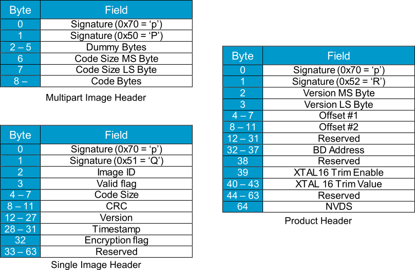
Figure 4 Multipart image, single image, and product headers
The secondary bootloader resides just after the header of our multipart image. When the device boots, it checks the offset fields of the product header to determine where the firmware images start, and also performs
some checks to validate the integrity of the images. It then compares the version of each firmware to assess which of the images is the most recent one, and then proceeds to boot the most
recent image. The developer should take care of the code size, so that an upgraded image will have enough space to reside in its appropriate memory segment. Note also that in the case
that you want the product header to reside in a different location, you would have to provide that location to the secondary bootloader by changing the PRODUCT_HEADER_POSITION macro definition.
4.2. Programming the SPI flash (DA145xx Pro Development Kit)
- Open SmartSnippets Toolbox. Select your device family and the JTAG interface and Open the profile. If you need more details on how to use the SmartSnippets Toolbox, you can consult the User Manual for the SmartSnippets Toolbox.
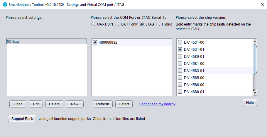
Figure 5 SmartSnippets Toolbox home screen
- On the ribbon, choose the SPI Flash/EEPROM utility.

Figure 6 SPI Flash/EEPROM utility
- Push the “Load hex/bin file” button. In the pop-up window, select the “Make single image” radio button and then browse through your files and select the first firmware image. This will create the first single image that we need for the multipart firmware. Press “Next”.
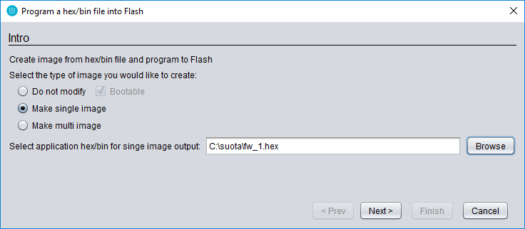
Figure 7 Select the first firmware image
- In the next screen you will be asked about the encryption key and initialization vector, as was the string array that we discussed previously. We will use the defaults in this case, but you can provide yours to better suit your needs. After that, press “Next”.
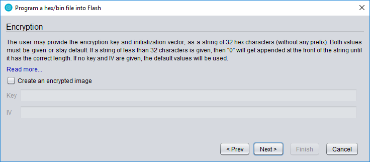
Figure 8 Encryption key and initialization vector
- Then select the output folder in which you want to save the single image.
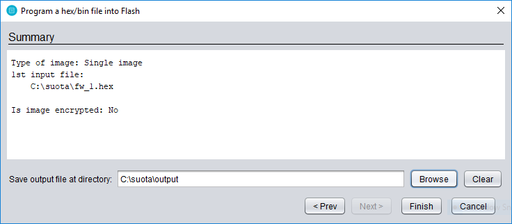
Figure 9 Select output folder of single image
- Repeat the above procedure for the second image file. After that, you will have two output files,
fw_1.imgandfw_2.img. - Push the “Load hex/bin file” button. In the pop-up window, select the “Make multi image” radio button this time, and then
browse through your files and select the
fw_1.img. Press “Next”.

Figure 10 Create multi image
- In the next screen, select the
fw_2.img. Press “Next”.
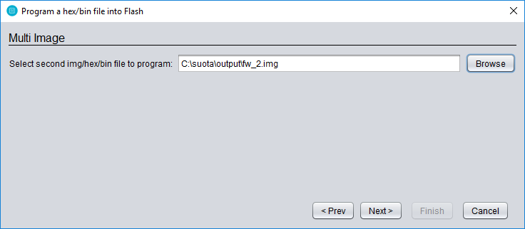
Figure 11 Select the second image file
- Provide the secondary bootloader that we have compiled earlier.

Figure 12 Secondary bootloader
- In the next screen, you can choose the memory location that the firmware images will reside. An important point is that the product header location must be the one that we defined previously in the secondary bootloader.
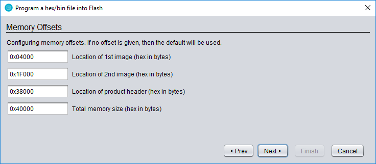
Figure 13 Memory offsets for firmware images and product header
- Choose the output folder for the multi image. Go through your settings one more time, and if you are satisfied, click finish. The SPI Flash Programmer will be updated and it’s ready to burn our multi image.
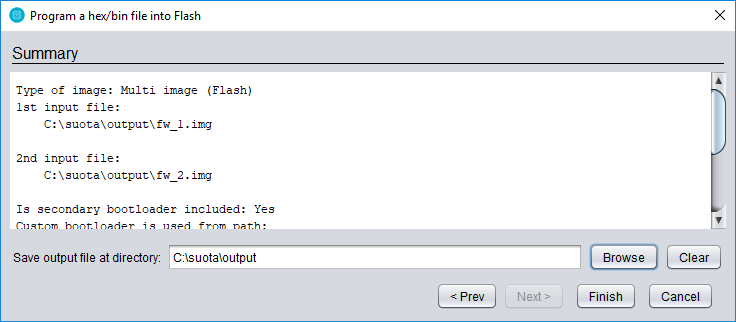
Figure 14 Summary of multi image
- Press “Connect” to connect to device, then “Erase” to erase your flash contents and then “Burn & Verify”. Push the Reset button on your board. The active image will be now running on your device.
4.3. Programming the SPI flash (DA14531 Module)
This section describes the changes that user needs to make in order to run SUOTA on the DA14531 module. These changes are due to the fact that the flash size which is embed in the DA14531 module is 128 Kbytes (1-MBit). The DA145xx Pro Development Kit has on board 2-Mbit SPI data Flash.
The Hardware connection when the module is connected to the DA145x development kit is shown in the following figure:

Figure 15 The DA14531 module connected to the DA14531 mother Board
- Change the SPI Flash memory size ((HEX, in Bytes) to 20000
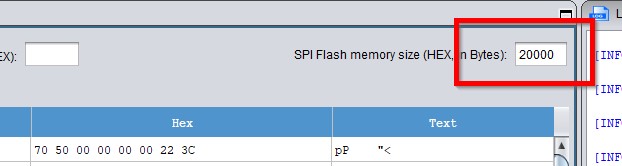
Figure 16 SPI Flash memory size
- Generate a new secondary bootloader image
Here you can follow the same steps as it is already described in the section 3.1.4, then do the following changes:
- Go into
bootloader.hand changePRODUCT_HEADER_POSITIONto 0x1F000
#define PRODUCT_HEADER_POSITION 0x1F000
- Go into
periph_setup.hand changeSPI_FLASH_DEV_SIZEto (128*1024)
- The memory location that the firmware images will reside should be changed to:

Figure 17 Memory offsets for firmware images and product header when the DA14531 Module is used
- In the application (project file) change the following in
app_suotar.h:
#define PRODUCT_HEADER_POSITION 0x38000
To
#define PRODUCT_HEADER_POSITION 0x1F000
4.4. Upgrading the firmware with the Dialog’s SUOTA App
You can easily upgrade the firmware over-the-air with Dialog’s SUOTA app, available on Android and iOS devices. Download it on your phone through the Apple App Store or Google Play.
- In the
output/folder you will find each firmware output in a.imgfile format. Copy the second image file on your phone in theSuota/folder by any means you are comfortable with (e.g. USB cable, download over the internet, etc.) - Open Dialog’s SUOTA app. Make sure your embedded device is running and hit the “Scan” button.

Figure 18 Dialog’s SUOTA home screen
- You should quickly see your device advertising. Click on your device’s name to begin the upgrade process.

Figure 19 Device selection screen
- Some basic information, like your device family and the SDK version it is using will be presented for you to check. Hit the “Update Device” button to continue.
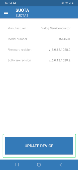
Figure 20 Device information
- Select the second firmware.
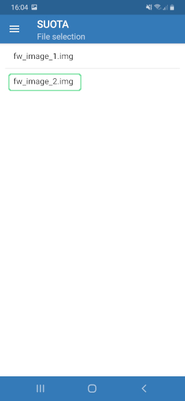
Figure 21 Firmware selection
- Configure the pins according to your device and select “Send to device”.

Figure 22 SPI pin configuration
- The upload process will begin. When it complete, a message will prompt you to reboot your device. Push “Yes”. You can verify that the update process succeeded by checking the advertised device name.

Figure 23 SUOTA upgrade complete
